Final Project
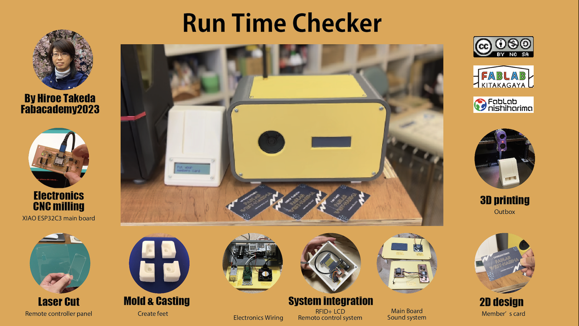
Welcome to My Final Project Page! by Hiroe Takeda
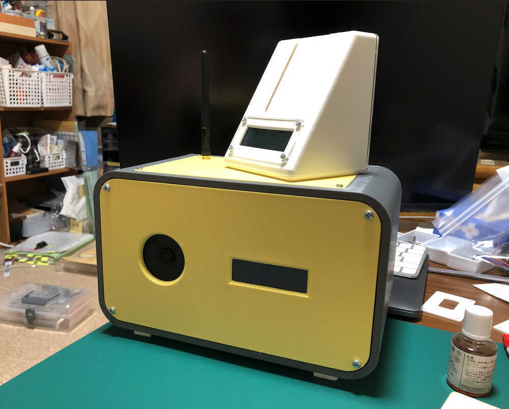
Final Result
In Week 17, I made slide and Video.
SLIDE
VIDEO
- Director: Hiroe Takeda
- Cast: Shin Masuoka / Yasuyuki Yanai / Kazunari Takeda / Hiroe Takeda
- Special Thanks: Professor Neil / Fab Lab Kitakagaya / Fab Lab West-harima / All Instructors
- Music: Sound made by PlayGround / Look Both Ways - Nathan Moore
First Idea
What will it do?
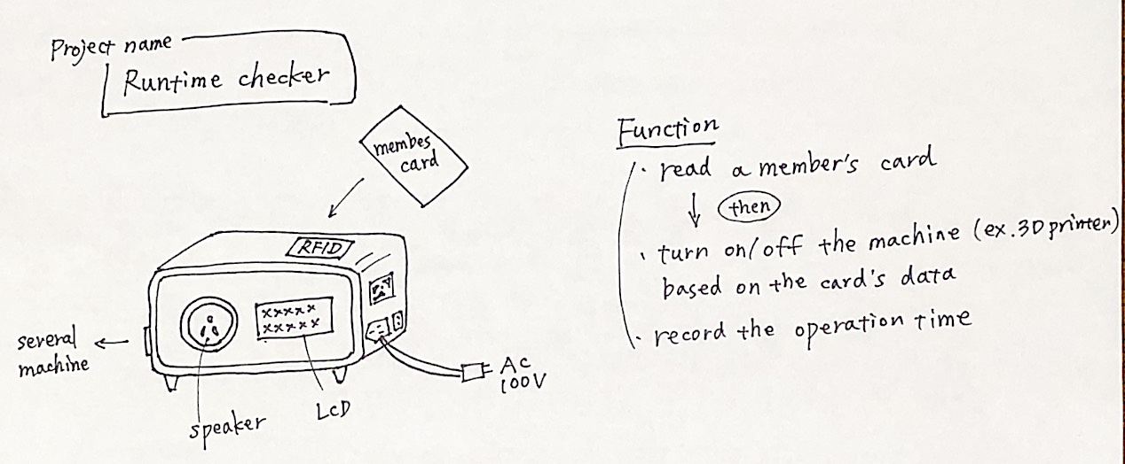
It has a function to read a member's card and turn on/off the machine based on the Mifare card’s data, and It can record the operation time. I call my final project Runtime checker. I search with google about runtime checker, It seems there in't same name.
How the idea was generated?
My final project idea is started when I noticed there is the problem in Fablab west-harima, and I want to solve the problem. At first, I must hearing the details of problem.
Hearing the Problems at Fab Lab West-Harima
- Not been able to keep track of the Operation training record for each machine for FabLab members.
- Many people who have not used machine for a long time have forgotten how to use it.
- Want to know the operating hours of each machine in order to use it for maintenance and upkeep of the machine.
- want to clarify the amount of time each member uses each machine.
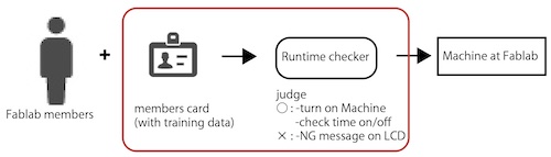
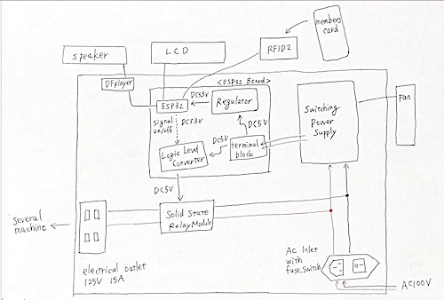
Making idea simply
- The secondly I thought, if there is a product reads the member's card, and if that device can operate the machine ON and OFF. And if the device can record time, it would solve the problem.
image
Japanese Radio law
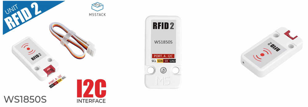
- During seaching site, I noticed there is Japanese Radio Law. And It was so difficult to find a product that was easy for individuals to purchase and that complied with Japanese radio laws. I must search a lots of site. Finaly, I find the RFID2 unit, this product that are not regulated by Japanese radio laws.
Who's done what beforehand?
There have been several RFID device.
- FABMAN
- Multi function AI punch the clock base on M5Stack, by vany5921
- Safe-Entry Access Machine by Team SEAM
- Tool management system, by Fab Academy 2017 student
There was a service with a similar idea called FABMAN, but I could not find the same idea for an individual project.
Electrical wiring work procedure (Plan)
- Under the presence and guidance of an electrician, Check electrical wiring and confirm operation.
- Perform work that does not require an electrician's license by yourself.
(Check with the electrician about the scope of work that can be done.) - Ask an electrician for work that requires an electrician's license
(check with the electrician to confirm the areas that require a request).
NOTE:
- For electrical wiring, it is necessary to comply with the laws set forth in each country.
- Do not work without a qualified electrician for work that requires qualifications.
- For work that requires qualifications, request work to be performed by qualified personnel.
- For work that can be performed by unqualified personnel, check with the certification body or qualified personnel in each country and perform the work within that category.
- If notification is required for installation, please submit the necessary notification to the respective organizations.
What purpose for?
The next, I clarified the purpose of the product.
Purpose
Using RFID, read the membership card to collate/record the following information and turn on/off the main power of the machine
- Reconciliation of the Operation training record
- Management of the Operation training record expiration dates (Expiration date management for those who have not used the equipment for a long period of time or for large equipment that requires periodic training)
- Management of machine availability (used to plan replacement of consumables and installation of maintenance equipment)
Using the above content, streamline the operational activities of the FabLab
Sketch
outline
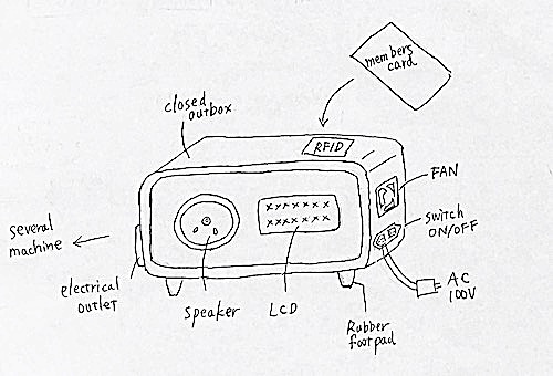
inside
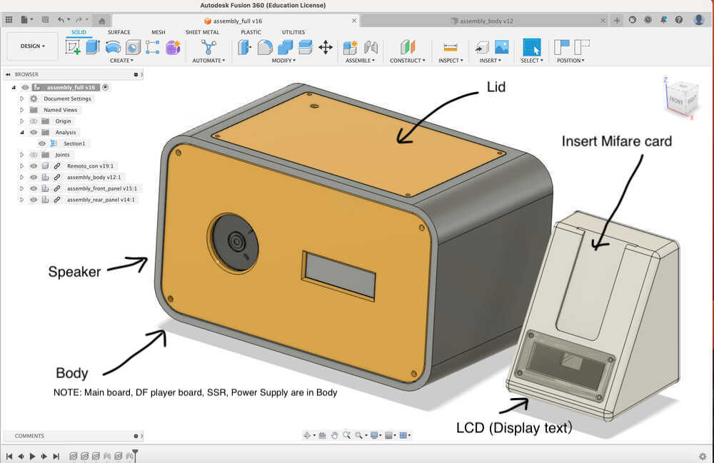
What will you design?
- Body of Device
- The design of Mifare card
What processes will be used?
| topic | Plan |
|---|---|
| 2D design | Members' card design |
| 3D design | Outbox and feed design |
| Subtractive - Laser cutting | A part of outbox |
| Subtractive - CNC milling | Board and feet milling |
| Additive - 3D printing | Outbox |
| Electronics Design | Design a XIAO ESP32 board |
| Embedded Programming | Embedded Programming with XIAO ESP32 board |
| molding and casting | Create feet |
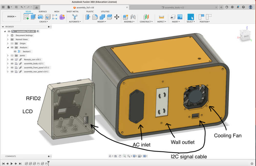
| output devices | DFplayer & speaker, LCD, Fan |
| input devices | RFID2 |
| networking and communications | Networking with XIAO ESP32 board |
NOTE:
- Plans are subject to change depending on circumstances.
BOM
AC and DC power supply related
Total: ¥15,730 (JPY)
| Part name | Q'ty | Unit Price | Sub Total | Where to buy |
|---|---|---|---|---|
| Solid State Module (SSR-40DA) |
1 | ¥1,000 | ¥1,000 | Akizuki |
| DC Fan 5V | 1 | ¥280 | ¥280 | Akizuki |
| Power Supply (RWS50B-5) | 1 | ¥5,600 | ¥5,600 | Digikey |
| Ac inlet (FN281-4-06) | 1 | ¥4,000 | ¥4,000 | Digikey |
| AC code 3pin | 1 | ¥900 | ¥900 | Monotarou |
| Wall outlet | 1 | ¥600 | ¥600 | Monotarou |
| Wifi Antenna 2.4GHz 5.8G | 1 | ¥250 | ¥250 | Amazon |
| USB 1.0cable typeC | 1 | ¥100 | ¥100 | 100 yen shop |
| USB 3.0cable typeA | 1 | ¥900 | ¥900 | Amazon |
| USB Extension Cable | 2 | ¥900 | ¥1,800 | Amazon |
| Wire (as needed) | - | ¥300 | ¥300 | Amazon |
NOTE:
- Prioritizing reliability, a high-brand switching power supply (RWS50B-5) and AC inlet (FN281-4-06) were used, but I think a low-cost power supply could have been procured for half the price.
- RFID2: Select this product that are not regulated by Japanese radio laws.
Electronics production
Main Board
Total: ¥1,774 (JPY)
| Parts | Quantity | Unit price | Sub Total | Where to buy |
|---|---|---|---|---|
| Proto Board FR1 | 1/3 board | ¥1,600 | ¥534 | DigiKey |
| Seeed Studio XIAO ESP32C3 | 1 | ¥940 | ¥940 | Akizuki |
| PinHeader_1x04_P2.54mm_Vertical_SMD | 3 | ¥30 | ¥90 | Akizuki |
| PinHeader_1x02_P2.54mm_Vertical_SMD | 1 | ¥30 | ¥30 | Akizuki |
| Photocoupler TLP293 | 1 | ¥30 | ¥30 | Akizuki |
| LED 1206 | 1 | ¥20 | ¥20 | Akizuki |
| Switch Button Omron B3SN | 1 | ¥20 | ¥20 | Akizuki |
| Resistor 1k ohm | 1 | ¥20 | ¥20 | DigiKey |
| Resistor 470 ohm | 1 | ¥50 | ¥50 | DigiKey |
| Resistor 0 ohm | 2 | ¥20 | ¥40 | DigiKey |
Sound board
Total: ¥2,170 (JPY)
| Parts | Quantity | Unit price | Sub Total | Where to buy |
|---|---|---|---|---|
| Proto Board FR1 | 1/4 board | ¥1,600 | ¥400 | DigiKey |
| DFplayer mini(DFR0299) | 1 | ¥810 | ¥810 | DigiKey |
| Speaker unit (8Ω 0.5W) | 1 | ¥120 | ¥120 | Akizuki |
| PinHeader_1x04_P2.54mm_Vertical | 1 | ¥30 | ¥30 | Akizuki |
| PinHeader_1x02_P2.54mm_Vertical | 1 | ¥30 | ¥30 | Akizuki |
| SD card (32GB) | 1 | ¥780 | ¥780 | Amazon |
NOTE: I think SD card could have been less expensive as I didn't need 32GB
Card reader /LCD connect board
Total: ¥2,055 (JPY)
| Parts | Quantity | Unit price | Sub Total | Where to buy |
|---|---|---|---|---|
| Proto Board FR1 | 1/4 board | ¥1,600 | ¥400 | DigiKey |
| RFID2 (U031-B) | 1 | ¥679 | ¥679 | DigiKey |
| LCD Module(AE-AQM1602A(KIT)) | 1 | ¥780 | ¥780 | Akizuki |
| PinHeader_1x04_P2.54mm_Vertical | 3 | ¥30 | ¥90 | Akizuki |
| Mifare card | 1 | ¥106 | ¥106 | Amazon |
Body parts
Total: ¥3.952 (JPY)
| Part name | Q'ty | Unit Price | Sub Total | Where to buy |
|---|---|---|---|---|
| Filament (PLA) Polyterra PLA 1.75mm | 0.80 | ¥3,300 (1kg) | ¥2,640 | Polymaker |
| Filament (ABS+) eSUN 1.75mm | 0.05 | ¥2,400 (1kg) | ¥120 | Amazon |
| Acrylic Sheet t2x160x180 | 1 | ¥270 d | ¥270 | Amazon |
| Insert Nuts M3x4mm x L 4mm | 46 | ¥10 | ¥460 | Amazon |
| Insert Nuts M4x6mm x L 6mm | 10 | ¥30 | ¥300 | Amazon |
| Screw M3x6 | 16 | ¥3 | ¥48 | Misumi |
| Screw M3x8 | 4 | ¥3 | ¥12 | Misumi |
| Screw M3x10 | 12 | ¥3 | ¥36 | Misumi |
| Screw M3x12 | 2 | ¥3 | ¥6 | Misumi |
| Screw M3x15 | 10 | ¥3 | ¥30 | Misumi |
| Screw M3x16 | 2 | ¥3 | ¥6 | Misumi |
| Screw M4x15 | 2 | ¥3 | ¥6 | Misumi |
| Washer M3 | 4 | ¥3 | ¥12 | Misumi |
| Washer M4 | 2 | ¥3 | ¥6 | Misumi |
- NOTE:
- Filaments were converted to actual amount used.
- ABS is used only for mounts where parts tend to generate heat. (ex: SSR mount base)
2D Model
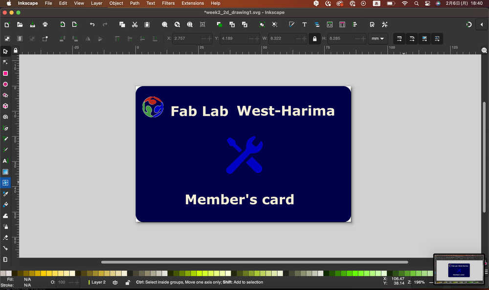
Prototype1
- In Week02, I designed Prototype1 of member's card, using Inkscape & Illustrator.
-> more details: Week02.
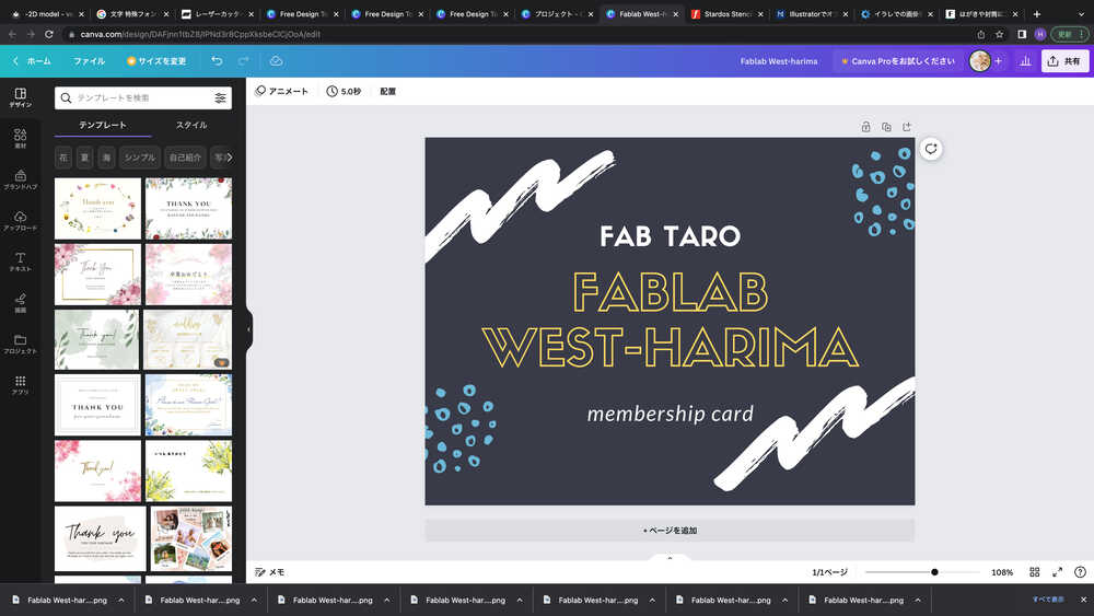
Prototype2
- In Week16, I check Prototype1, and found logo could not be made clear shape and the color was dark. I designed Prototype2 of member's card, using Canva free format, and edit the color and text, and export png file. It seems better than Prototype1.
- Printout with Label seal A-one, and paste to Mifare card.
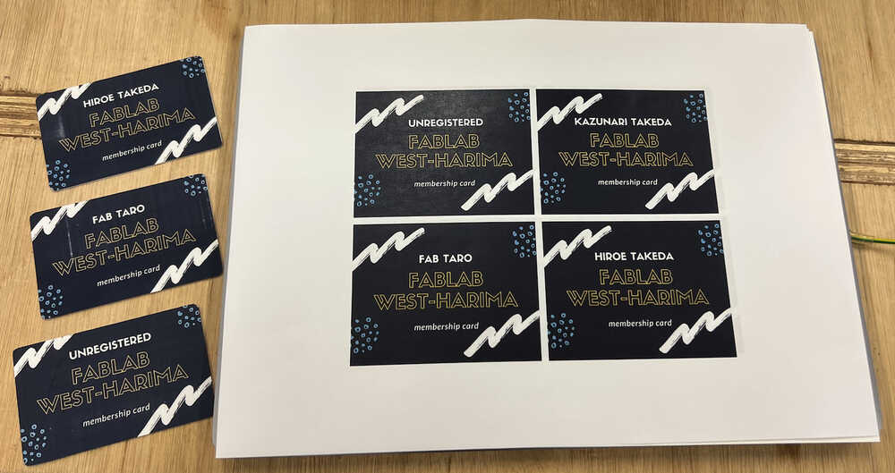
- Set to card holder. The size seems good.
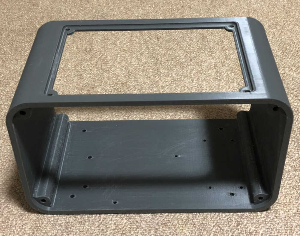
3D Model
Prototype1
- In week02, I designed the rough prototype of outbox, using Fusion360.
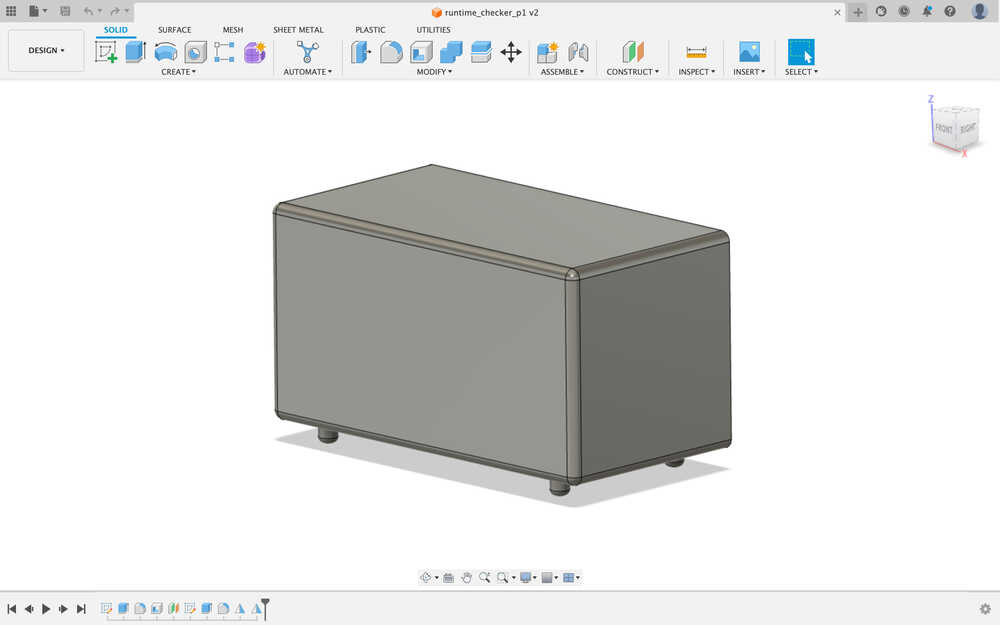
Prototype2
- Since week02 (3D model) is only designed a simple model, I re-create Prototype2.
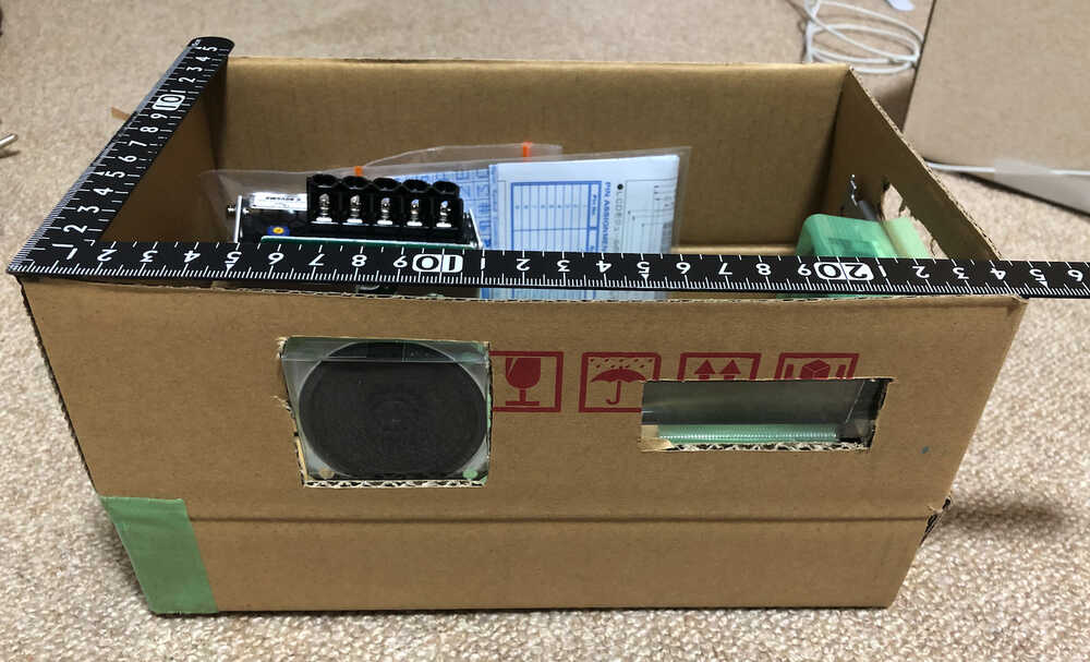
- I considered the proper size with cardboard box that I cut with a cutter.
- I create 3D model (Prototype2) by Fusion360.
3D Printhing
The several parts of final project were output.
- Machine: VORON 2.4 R2
- Material: PLA and ABS (ABS is used only for mounts where parts tend to generate heat. (ex: SSR mount base)
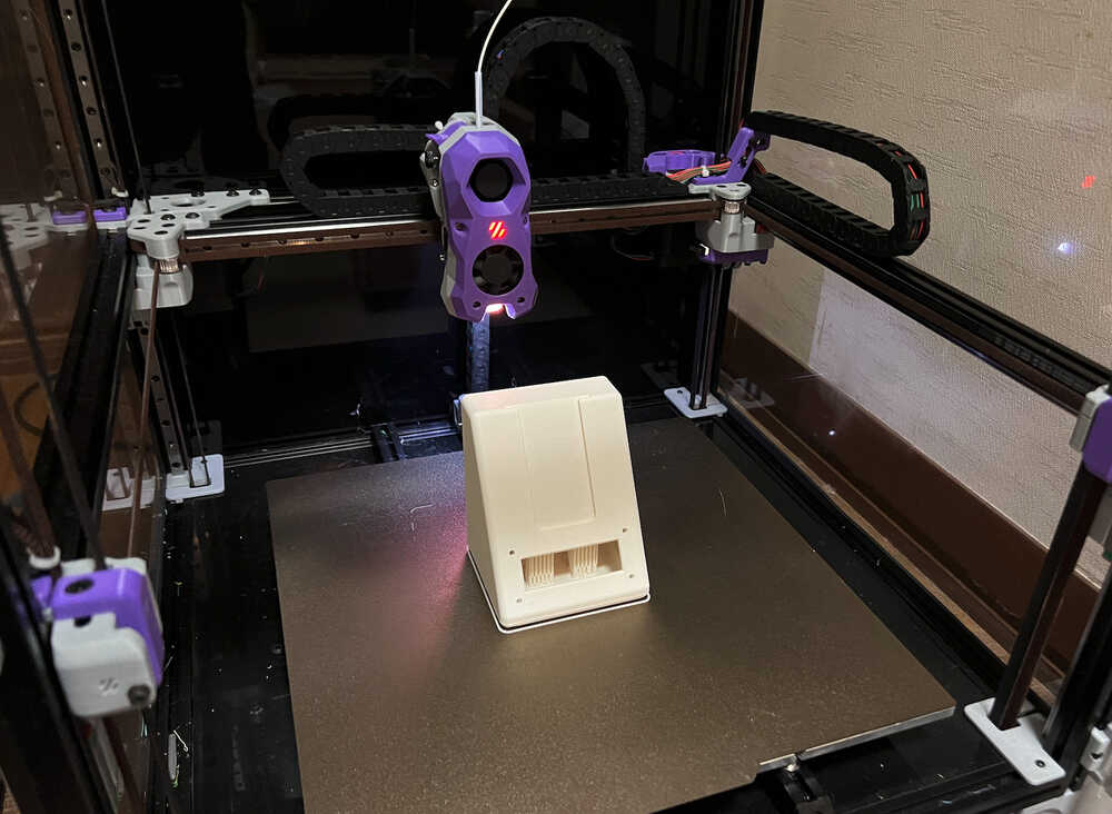
The Body, it took about 13.5 hours to output.
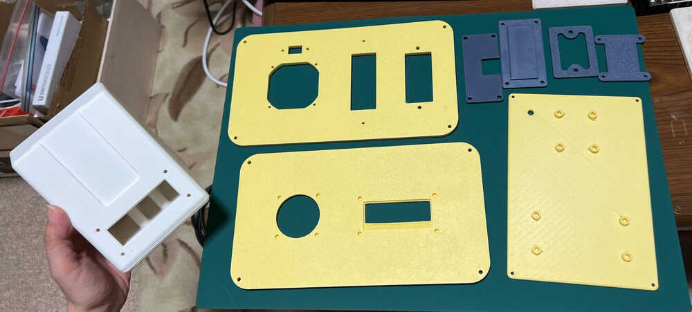
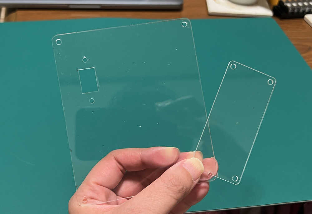
Laser cut
The 2 panel for final project, cut by Laser cutting machine.
- Machine: FABOOL Laser CO2
- Material: Acrylic Sheet t2
- Parameter: Speed 1000 / Power 60 / Times 2
NOTE: The SVG file to cut with laser cut is made by Fusion360 add-in shaper utilities. The details to do is in Week03.
Electronics Design & Production
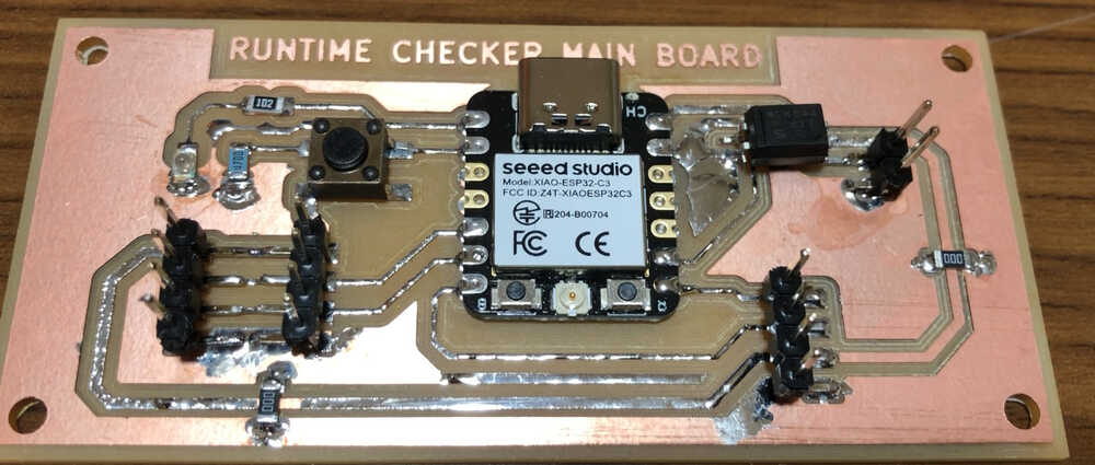
Main board
With several trial, I created the prototype of the board for my final Project. I think that Electronics Design is one of the most difficult tasks that required a lot of effort. During works It is important to look the datasheet.
The latest board is below, made by week09.
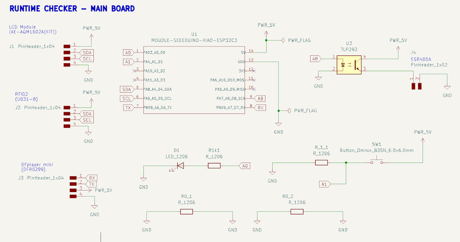
- Schematic
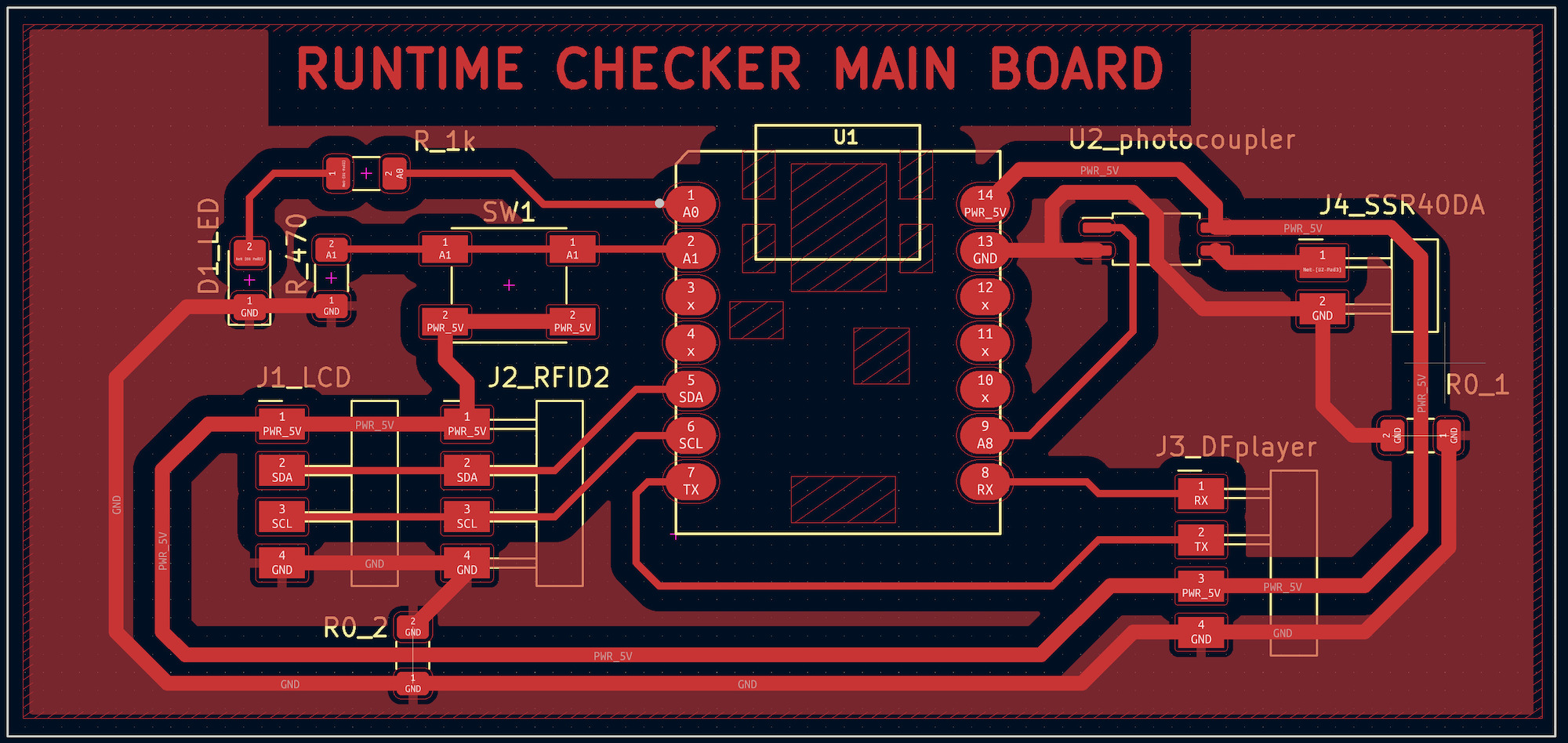
- Board design
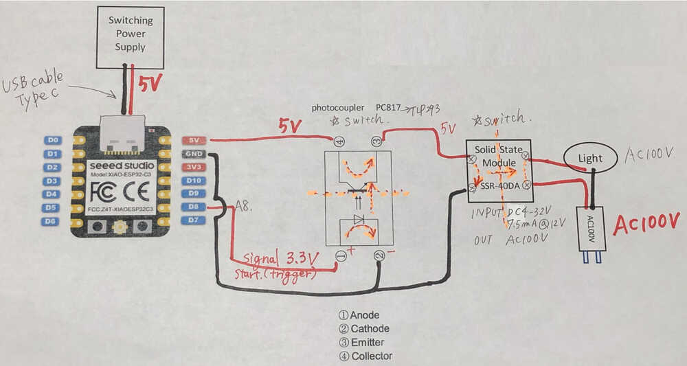
Why I add photocoupler?
- Changing the input signal voltage of the Solid State Relay Module (SSR-40DA).
Old version :3-32V
New version :4-32V
(Input control voltage of DC5V or more is recommended for stable operation.)
Datasheet - The input signal voltage of the SSR used was 4-32V and could not be driven by the digital pin voltage (3.3V) of the ESP32C3.
- For the above reasons, I thought of using some kind of device such as a FET or logic level converter to control the 5V voltage with a 3.3V signal voltage.
- For the device to be used, I decided to use a photocoupler that was stocked in large quantities at home.
(I figured I didn't want to pay 1000 yen shipping to buy one FET for 60 yen)
- Data file:
- Datasheet
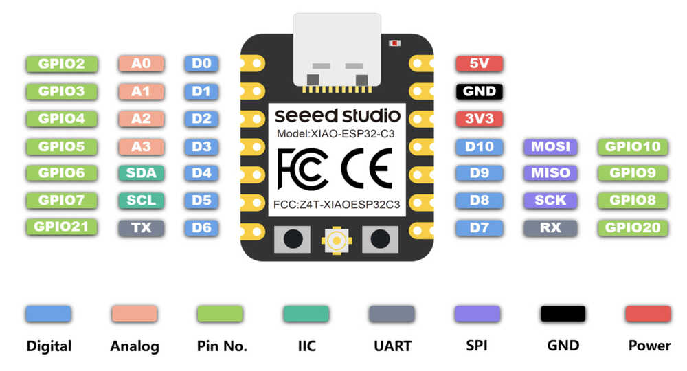
- Pinout of XIAO ESP32-C3
Sound board (DFplayer mini)
- Data file
- Schematic and Board design are below.
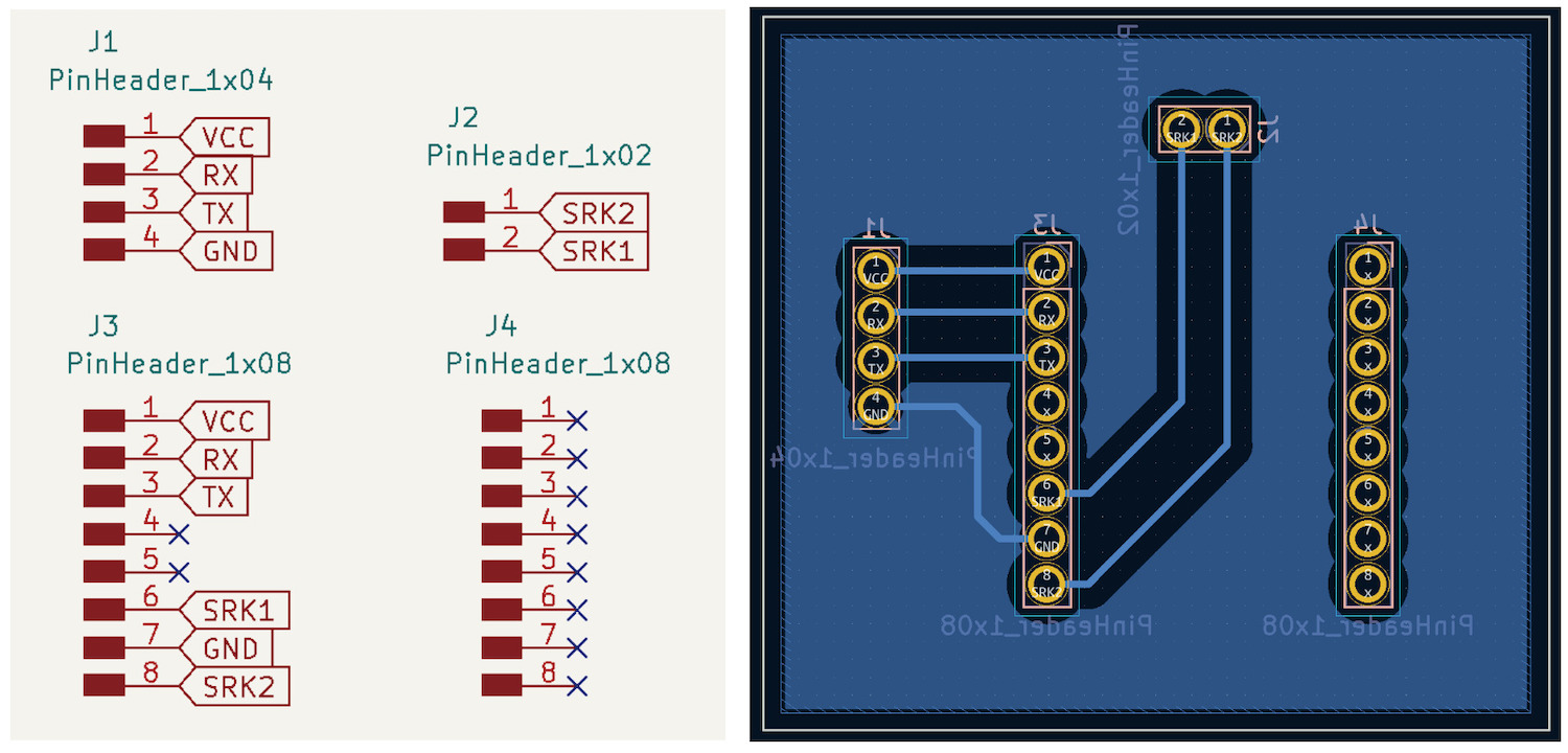
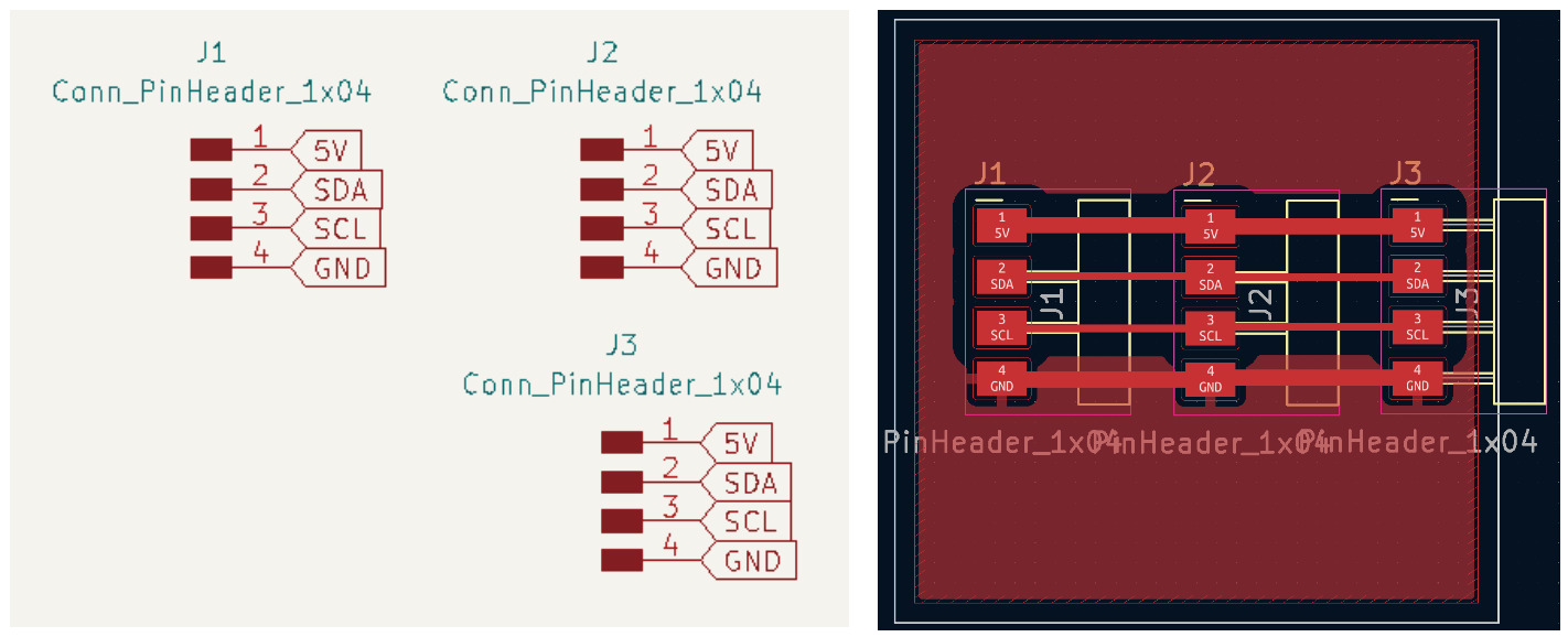
Card reader / LCD connect board
- Data file
- Schematic and Board design are below.
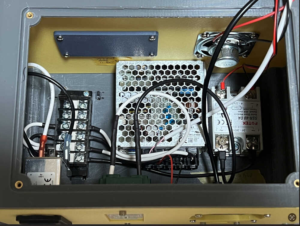
Assemble / Wiring
Wire Work
- Since high voltages are handled, it should be taken into account and adequate safety measures (e.g., use appropriate cables...) should be taken.
- After receiving advice from a qualified electrician, the following cables were selected for use with Japanese household power (100V 15A).
- VVF cable (2.0mm^2) Allowable current 23A
- IV cable (2.0mm^2) Permissible current 35A
Put insert to mount and panel and body. then screw down parts and boards.
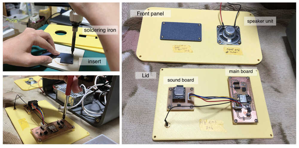
Make wire and connect to devices.
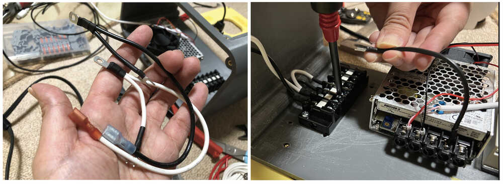
Connect AC and DC power supply related.
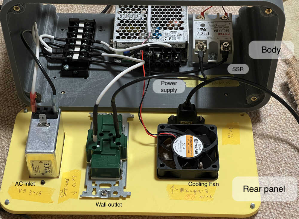
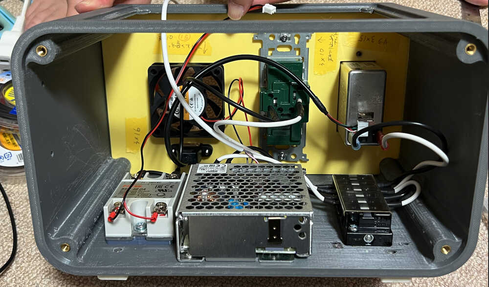
Rear panel mounted on body.
Front panel mounted on body
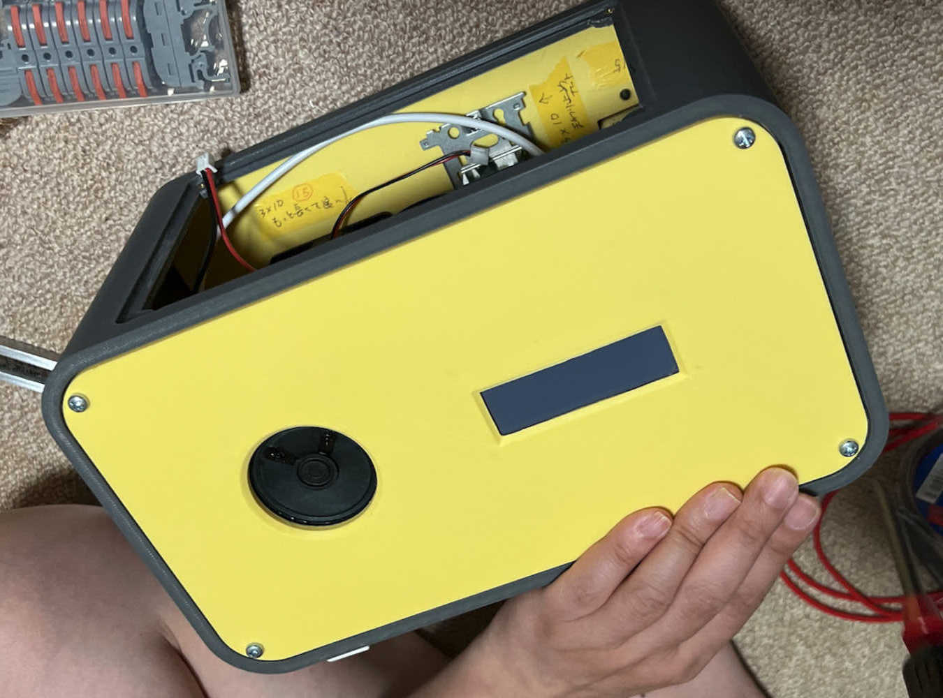
Assemble for Remote Controller parts and devices.
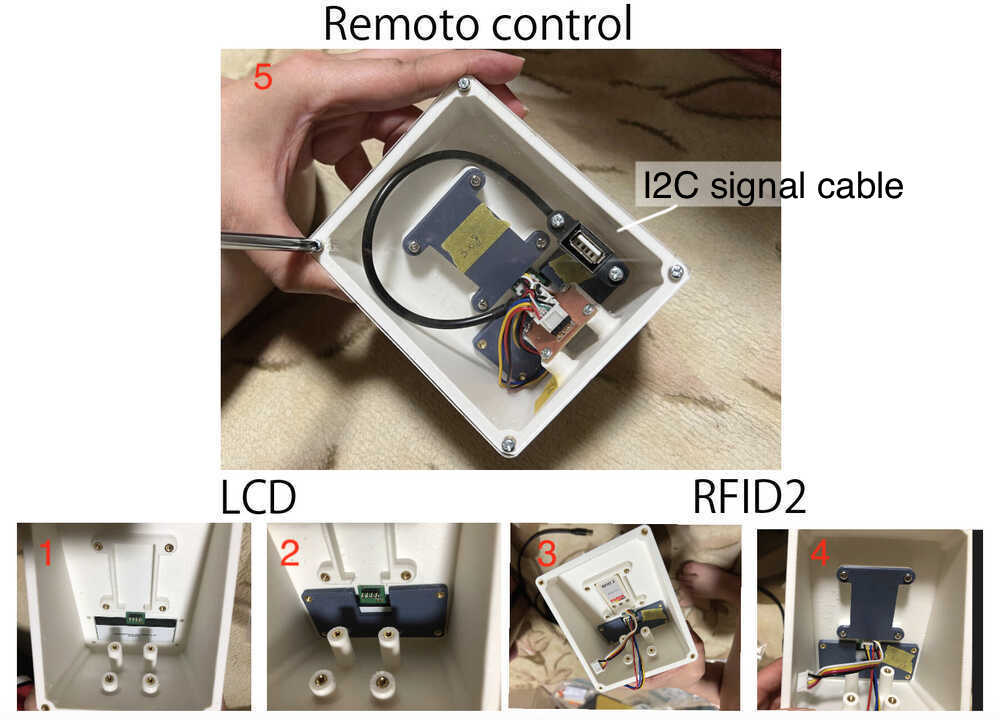
Assembly complete
Output Divice
In Week09, I work with Solid State Module(SSR-40DA).
Programming microcontroller board with Seeed Studio XIAO ESP32C3 which I designed to turn on the Heat Gun (AC100V) using SSR-40DA. This result make me happy.
How to connect
I use ChatGPT for programming. Programming code is below.
const int SSRPin1 = D8;//Solid State Module outpin
const int buttonPin = D1;// button pin  ESP32C3 pin D7
int buttonState = 0;//initial state of the button
int i = 0; //variable intensity led

void setup() { //declaration of inputs and outputs
  pinMode(SSRPin1, OUTPUT);
  pinMode(buttonPin, INPUT);
}
void loop() {
  buttonState = digitalRead(buttonPin);// we read the state of the button
  if (buttonState == HIGH) { //if we press the button
  digitalWrite(SSRPin1, HIGH);
  delay(4000);
  digitalWrite(SSRPin1, LOW);
  delay(4000);

}
  else {  //if we don't press the button
  digitalWrite(SSRPin1, LOW);
  }
}
Input Device
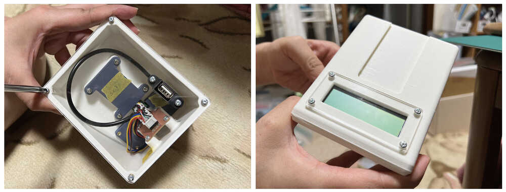
In Week11, I work with RFID2.
 RFID2 to a microcontroller board that I have designed and read the Mifare card.
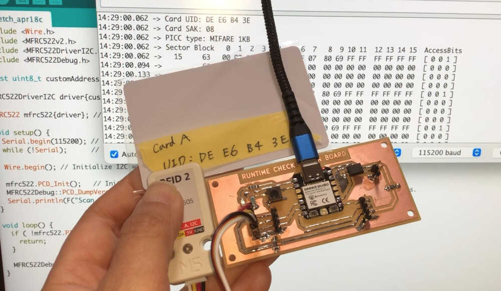
I generated a code in ChatGPT that reads the card and displays the UID of the card. The code is below.
#include <Wire.h>
#include <MFRC522v2.h>
#include <MFRC522DriverI2C.h>
#include <MFRC522Debug.h>

const uint8_t customAddress = 0x28;

MFRC522DriverI2C driver{customAddress, Wire}; // Use the standard Wire object for I2C driver.

MFRC522 mfrc522{driver}; // Create MFRC522 instance.

void setup() {
  Serial.begin(115200); // Initialize serial communications with the PC for debugging.
  while (!Serial);      // Do nothing if no serial port is opened (added for Arduinos based on ATMEGA32U4).

  Wire.begin(); // Initialize I2C with default SDA and SCL pins.

  mfrc522.PCD_Init();   // Init MFRC522 board.
  MFRC522Debug::PCD_DumpVersionToSerial(mfrc522, Serial); // Show details of PCD - MFRC522 Card Reader details.
  Serial.println(F("Scan PICC to see UID, SAK, type, and data blocks..."));
}

void loop() {
  if ( !mfrc522.PICC_IsNewCardPresent() || !mfrc522.PICC_ReadCardSerial()) {
    return;
  }

  MFRC522Debug::PICC_DumpToSerial(mfrc522, Serial, &(mfrc522.uid));
}
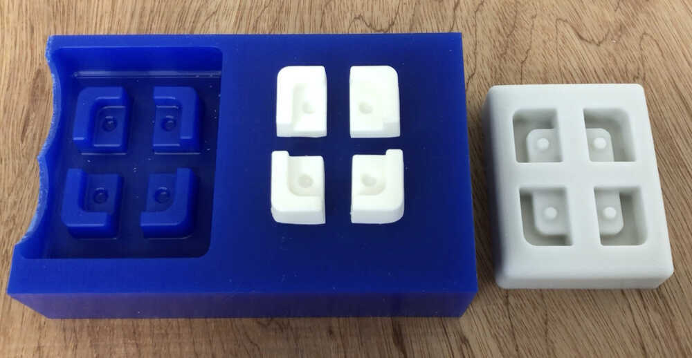
Molding and Casting
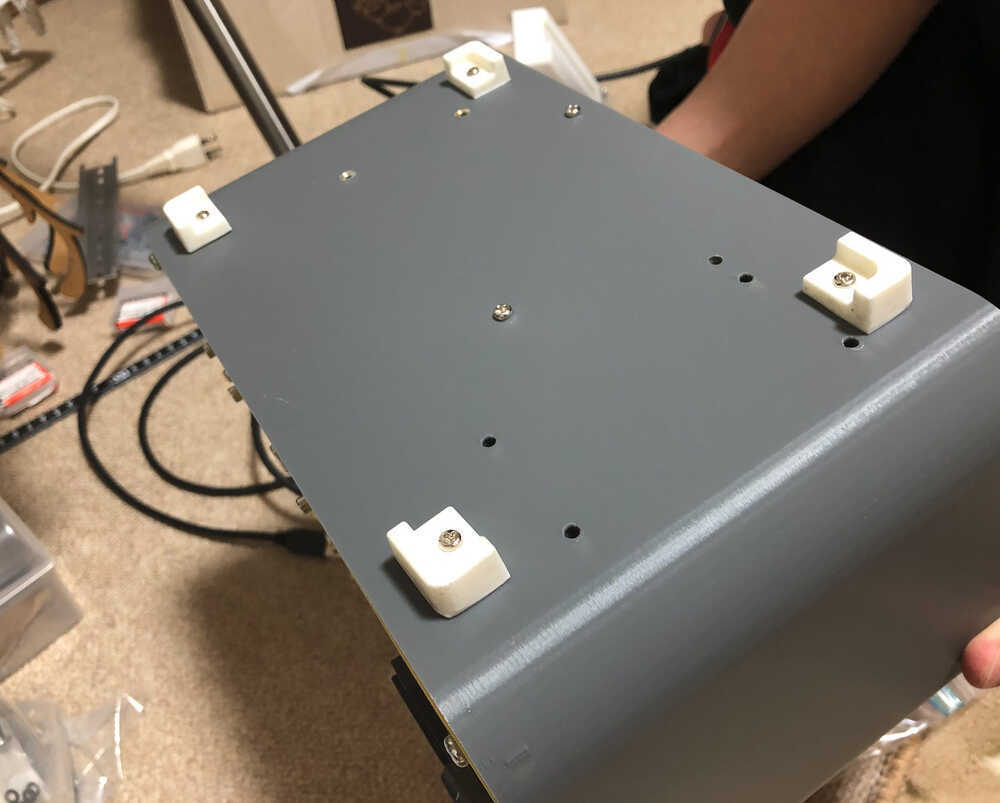
In week12, I made the feet for my final Project, with Milling Molding Wax & Molding by silicone, and Casting by polyurethane resin.
 Drill holes。
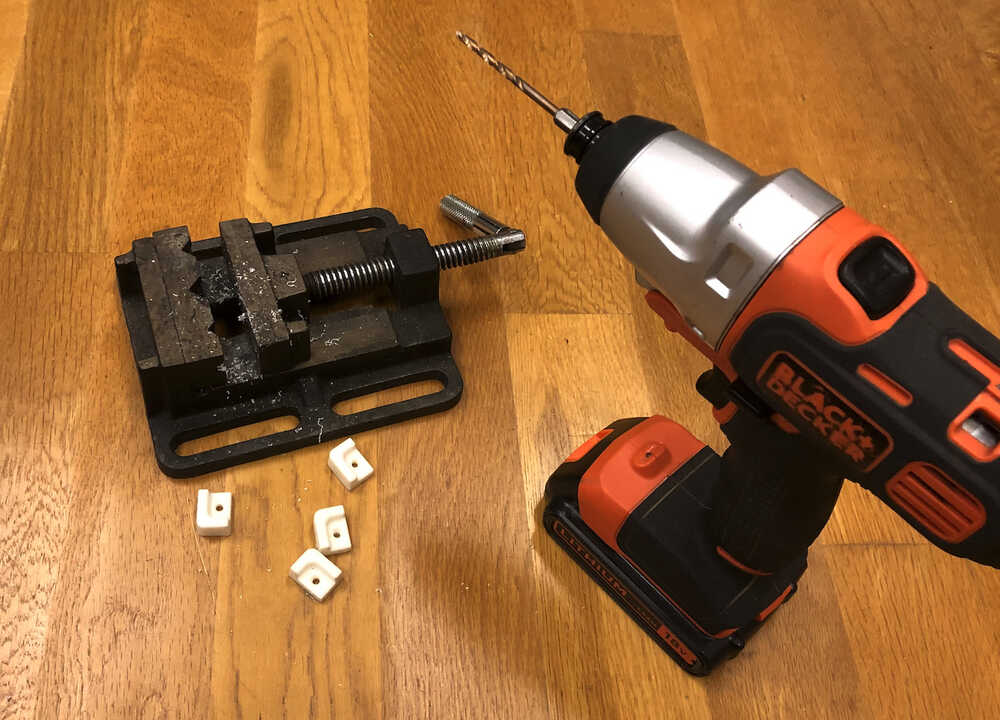 The feet is set on the bottom of body.
Networking and communications
- In week13. I checked the communications of nords for my final Project.
- Read the Mifare card by RFID2, and depends on Authentication UID or Un-authentication of Mifare card, turn on/off SSR-40DA, and display text to LCD, and play sound by DF player mini.
I use below nord and Board and IDE as following.
| title | Description |
|---|---|
| Nord | RFID2, SSR-40DA, LCD Module(AE-AQM1602A), DFplayer mini(DFR0299) |
| Board | Seeed XIAO ESP32C3 board, designed by week09 for my final Project |
| IDE | Arduino IDE |
| Communication | I2C x2, Serial communication x1, Wifi |
| others | Mifare card, Speaker (8Ω 0.5W), MicroSDcard |
VIDEO
Communication diagram
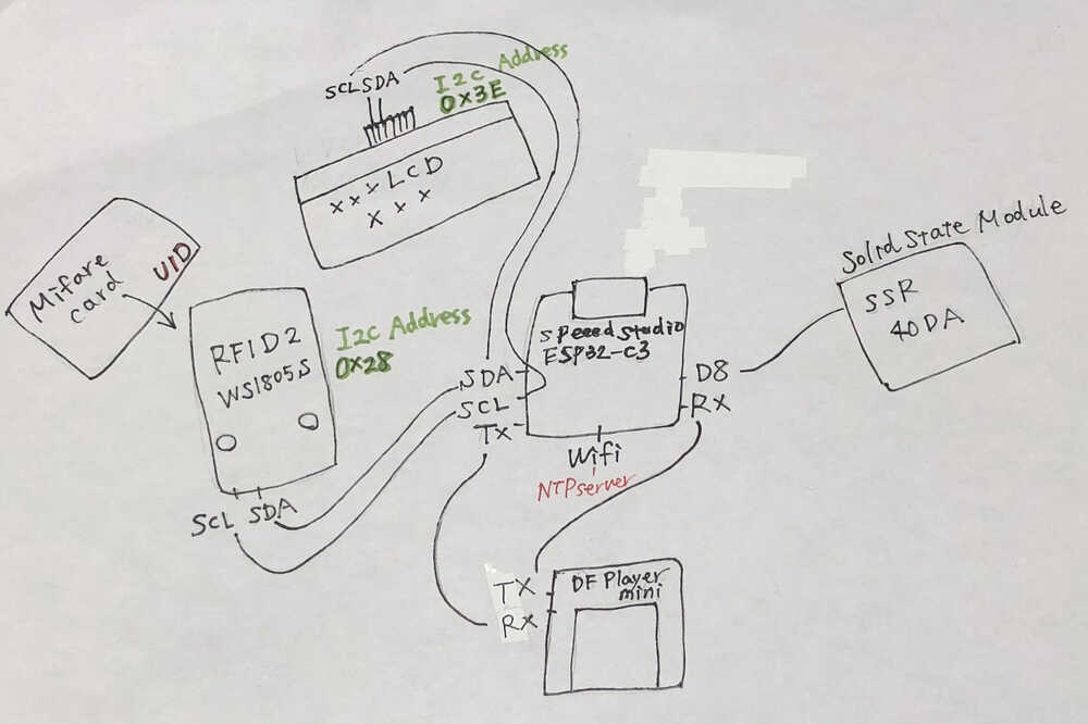
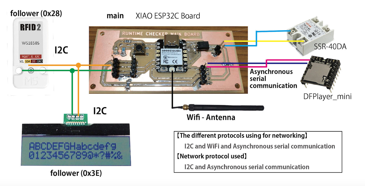
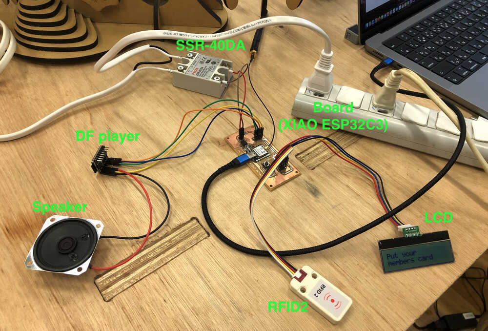
How to connect
Code (Final)
I generated The program code using ChatGPT about Solid State Module in Week09, RDID2 in Week11, Networking and communications in Week13. with checking the operation of the devices one by one.
The Final code details are below.
This code is an Arduino-based RFID card reader system that uses an RFID reader module called MFRC522 to read the card and compare it with the registered card information for authentication. It also uses an audio player module called DFRobotDFPlayerMini to play audio for various situations. Additionally, it has the ability to display messages on the LCD display.
Below is a detailed description of each part.
| Syntax | Description |
|---|---|
| 1. library inclusion: | Include the required libraries. This includes Wire (I2C communication), MFRC522v2 (RFID reader), WiFi (wireless connectivity), time (time-related processing), SoftwareSerial (software serial communication), and DFRobotDFPlayerMini (audio player). |
| 2. global variable definitions: | Defines variables used throughout the program, including RFID reader, card information, card current status, audio playback status, SoftwareSerial communication, and audio player. |
| 3. setup functions: | initialize hardware and set up WiFi connection. It also initializes the audio player and plays audio to start the system. |
| 4. Loop function: | reads the card, compares it with the registered information, and performs actions according to its status (play audio, update LCD, etc.). This function is looped continuously while the Arduino is running. |
| 5. other functions: | functions are defined to perform specific functions such as formatting the UID of the card, updating the LCD, connecting to WiFi, getting the time, checking the expiration date, etc. |
Specific actions include: when a registered card is read, the card's expiration date is checked, and if it has not expired, the LED is lit, an audio is played, and a message is displayed on the LCD. If a non-registered or expired card is read, a different voice is played and a warning message is displayed on the LCD.
// Hiroe Takeda. Fab Academy 2023
//【Final code for Runtime checker 】2023/5/19
// CC BY-NC-SA
// XIAO ESP32C3
// Fab Lab Kitakagaya, Fab Lab West-harima

#include <Wire.h>
#include <MFRC522v2.h>
#include <MFRC522DriverI2C.h>
#include <MFRC522Debug.h>
#include <WiFi.h>
#include <time.h>
#include <SoftwareSerial.h>
#include <DFRobotDFPlayerMini.h>

const uint8_t customAddress = 0x28;
const uint8_t DEVICE_ADDRESS = 0x3E;

MFRC522DriverI2C driver{customAddress, Wire};
MFRC522 mfrc522{driver};

struct CardInfo {
  const char* uid;
  const char* userName;
  const char* expiryDate;
};

CardInfo registeredCards[] = {
  {"5E4ABC3E", "HIROE TAKEDA", "20240501"},
  {"DEE6B43E", "KAZUNARI TAKEDA", "20240501"},
  {"DE1AB83E", "FABLAB TARO", "20221001"}
};

// WiFi Network Information
struct WifiNetwork {
  const char* ssid;
  const char* password;
};

WifiNetwork wifiNetworks[] = {
  {"Wifi_SSID1", "Wifi_Password1"},
  {"Wifi_SSID2", "Wifi_Password2"},
  // Add more networks as needed
};

bool soundPlayed = false;
const uint8_t ssr = 8;

enum CardStatus {
  NO_CARD,
  REGISTERED_CARD,
  UNREGISTERED_CARD
};

CardStatus currentStatus = NO_CARD;

char lastUid[9] = "";
char lastUserName[17] = "";
bool countTime = false;
time_t cardAuthStartTime;

SoftwareSerial mySoftwareSerial(20, 21);
DFRobotDFPlayerMini myDFPlayer;

bool uidMatches(MFRC522::Uid *uid1, const char *uid2) {
  if (uid1->size != 4) {
    return false;
  }

  for (uint8_t i = 0; i < uid1->size; i++) {
    char buf[3] = {uid2[i * 2], uid2[i * 2 + 1], '\0'};
    uint8_t uid2Byte = strtol(buf, nullptr, 16);
    if (uid1->uidByte[i] != uid2Byte) {
      return false;
    }
  }
  return true;
}

const char* formatUid(MFRC522::Uid *uid) {
  static char buf[9];
  for (uint8_t i = 0; i < uid->size; i++) {
    snprintf(&buf[i * 2], 3, "%02X", uid->uidByte[i]);
  }
  return buf;
}

void printCardDetails(MFRC522::Uid *uid) {
  for (uint8_t i = 0; i < uid->size; i++) {
  }
}

void setup() {
  Wire.begin();
  mfrc522.PCD_Init();
  pinMode(ssr, OUTPUT);
  init_LCD();

  connectToWifi();
  obtainTime();

  // DFPlayer setup
  mySoftwareSerial.begin(9600);
  while (!myDFPlayer.begin(mySoftwareSerial)) {
    delay(300);
  }
  myDFPlayer.setTimeOut(500); // Set serial communication time out 500ms
  myDFPlayer.volume(30); // DFPlayer volume value. From 0 to 30
  myDFPlayer.play(1); // Play the System Opening : Sound No.1
  delay(2000);
}

void loop()

{
  // Check WiFi connection and reconnect if disconnected
  if(WiFi.status() != WL_CONNECTED) {
    connectToWifi();
    obtainTime();
  }

  bool cardPresent = mfrc522.PICC_IsNewCardPresent() &&
  mfrc522.PICC_ReadCardSerial();
  CardStatus newStatus;

  if (cardPresent) {
    printCardDetails(&(mfrc522.uid));

    bool isRegistered = false;
    bool isExpired = false;

    for (uint8_t i = 0; i < sizeof(registeredCards) / sizeof(registeredCards[0]); i++) {
      if (uidMatches(&(mfrc522.uid), registeredCards[i].uid)) {
        isRegistered = true;
        strncpy(lastUid, registeredCards[i].uid, sizeof(lastUid));
        strncpy(lastUserName, registeredCards[i].userName, sizeof(lastUserName));

        if (isDateExpired(registeredCards[i].expiryDate)) {
          isExpired = true;
        }

        break;
      }
    }

    if (isRegistered && !isExpired) {
      digitalWrite(ssr, HIGH);
      newStatus = REGISTERED_CARD;
      if (!soundPlayed) {
        myDFPlayer.play(2); //Play the Sound for the turn on: Sound No.2
        soundPlayed = true;
      }
      delay(2000);

      while (mfrc522.PICC_IsNewCardPresent()) {
        delay(100);
      }
    } else {
      digitalWrite(ssr, LOW);
      newStatus = UNREGISTERED_CARD;
      if (isExpired) {
        myDFPlayer.play(5); // Play the Sound for expired cards : Sound No.5
      } else {
        myDFPlayer.play(3); //Play the Sound for not authorized: Sound No.3
      }
      delay(4000);
      updateLCD("Not authorized", "or expired");
    }
  } else {
    digitalWrite(ssr, LOW);
    newStatus = NO_CARD;
    soundPlayed = false;
    if (currentStatus != newStatus) {
      myDFPlayer.play(4); //Play the Sound for the turn off: Sound No.4
      delay(2000);
    }
  }

  if (newStatus != currentStatus) {
    currentStatus = newStatus;

    switch (currentStatus) {
      case NO_CARD:
        if (countTime) {
          time_t elapsedTime = time(nullptr) - cardAuthStartTime;
          unsigned long hours = elapsedTime / 3600;
          unsigned long minutes = (elapsedTime % 3600) / 60;
          unsigned long seconds = elapsedTime % 60;
          char elapsedTimeStr[17];
          snprintf(elapsedTimeStr, sizeof(elapsedTimeStr), "%luh %lum %lus", hours, minutes, seconds);
          updateLCD(elapsedTimeStr, lastUserName);
          countTime = false;
        } else {
          updateLCD("Put your", "members card");
          delay(2000);
        }
        break;
      case REGISTERED_CARD:
        updateLCD("Welcome FabLab", lastUserName);
        cardAuthStartTime = time(nullptr);
        countTime = true;
        break;
      case UNREGISTERED_CARD:
        updateLCD("Not authorized", "or expired");
        delay(4000);
        break;
    }
  }
}

void updateLCD(const char* line1, const char* line2) {
  writeCommand(0x01); // Clear Display

  // Write first line
  for (int i = 0; line1[i] != '\0' && i < 16; i++) {
    writeCommand(0x80 + i);
    writeData(line1[i]);
  }

  // Write second line
  for (int i = 0; line2[i] != '\0' && i < 16; i++) {
    writeCommand(0xC0 + i);
    writeData(line2[i]);
  }
}

void writeData(byte toSend) {
  Wire.beginTransmission(DEVICE_ADDRESS);
  Wire.write(0x40);
  Wire.write(toSend);
  Wire.endTransmission();
}

void writeCommand(byte toSend) {
  Wire.beginTransmission(DEVICE_ADDRESS);
  Wire.write(0x00);
  Wire.write(toSend);
  Wire.endTransmission();
}

void init_LCD() {
  writeCommand(0x38);
  writeCommand(0x39);
  writeCommand(0x14);
  writeCommand(0x79);
  writeCommand(0x50);
  writeCommand(0x6C);
  delay(250);
  writeCommand(0x38);
  writeCommand(0x0C);
  writeCommand(0x01);
  delay(2);
}

void connectToWifi() {
  WiFi.mode(WIFI_STA);

  // Try to connect with each access point
  for(uint8_t i = 0; i < sizeof(wifiNetworks) / sizeof(WifiNetwork);i++) {
    WiFi.begin(wifiNetworks[i].ssid, wifiNetworks[i].password);

    uint8_t attempt = 0;
    while (WiFi.status() != WL_CONNECTED && attempt < 30) {
      delay(500);
      attempt++;
    }
    // If connection was successful, exit the loop
    if(WiFi.status() == WL_CONNECTED) {
      break;
    }
  }

  if(WiFi.status() == WL_CONNECTED) {
    // print your local IP address:
    Serial.print("Connected to network: ");
    Serial.println(WiFi.localIP());
  }
}

void obtainTime() {
  //set NTP server pool
  configTime(0, 0, "pool.ntp.org");

  // Wait for time to be set (by the network)
  const int maxRetries = 10;
  int retries = 0;
  while(time(nullptr) < 1619042464L && retries < maxRetries) {
    Serial.println("Waiting for time to be set...");
    delay(1000);
    retries++;
  }
}

bool isDateExpired(const char *expiryDate) {
  time_t now;
  time(&now);
  struct tm * timeinfo;
  timeinfo = localtime (&now);
  char currentDate[9];
  sprintf(currentDate, "%04d%02d%02d", timeinfo->tm_year + 1900, timeinfo->tm_mon + 1, timeinfo->tm_mday);
  return strcmp(currentDate, expiryDate) > 0;
}
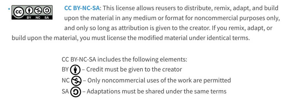
License
In my case, I decided to grant the following license "CC BY-NC-SA" for my project for all copyrighted works.

This license allows re-users to distribute, remix, adapt, and build upon the material in any medium or format for noncommercial purposes only, and only so long as attribution is given to the creator. If people remix, adapt, or build upon the material, you must license the modified material under identical terms.
Reference from Creative Commons
My thought
- For me, all assignment are not easy, very tough work. Many software and tools were used for the first time and errors occurred frequently. There were many difficult hours.
- As It was obvious to me that I did not have enough skills before Fab Academy, I did self bootcamp about 6 months, learning the role and function of electronic parts, and board creation with Kicad and milling machine etc. The self bootcamp (spartan training) helps me a lot.
- I consider the device for final project during bootcamp every day, It bedome good training too.
- In week assignment, I tried to related with final project. It was good for me, as I think that my work is not so fast.Some weeks did not go as planned, and the work each week was difficult each time, but by the end I could see the shape of the project.
Data file
- 2D model - members card design (png)
- 3D model - Full Body (f3z)
- 3D printing
- Body
- Front panel (stl), Front panel part
- Rear panel (stl)
- Remoto control parts
- Laser cut