- CDS
This page is my work process for week 11 Input device, CDS.
I refer to The Strange Storage and burariweb. I add CDS on my designed board and read it to Fab-Xiao RP2040.
1. Input device and IDE, I used
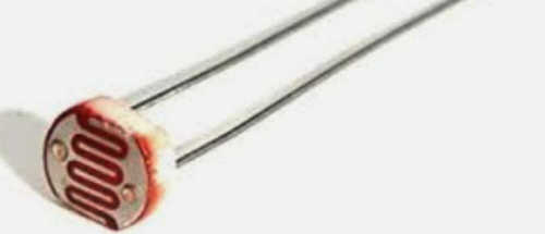
- CDS
- CDS is a light sensor using CdS (cadmium sulfide), a resistor whose electrical resistance decreases in accordance with the intensity of light
- IDE
- I use Arduino IDE
- about Arduino IDE, I explain in Week04
- I use Processing to see visual bar of sensor analog Value.
I got the Processing information from Adrian and Adrian's Fab-Xiao site. thanks a lot!

The Processing is an open source project by Casey Reas and Benjamin Fry, formerly of the MIT Media Lab. It is a programming language and integrated development environment (IDE) for electronic art and visual design. It eliminates detailed configuration functions for content creation work by artists. It is a simplified version of Java that specializes in graphic features.
How to use Processing
1. Download Processing.(only first time)
2. You need only to download the code of arduino and the code for processing. and Port change to yours.
2. Board
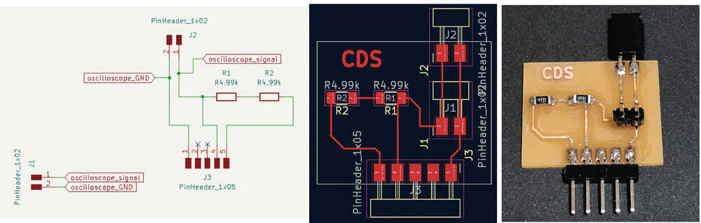
I make Test board for CDS.
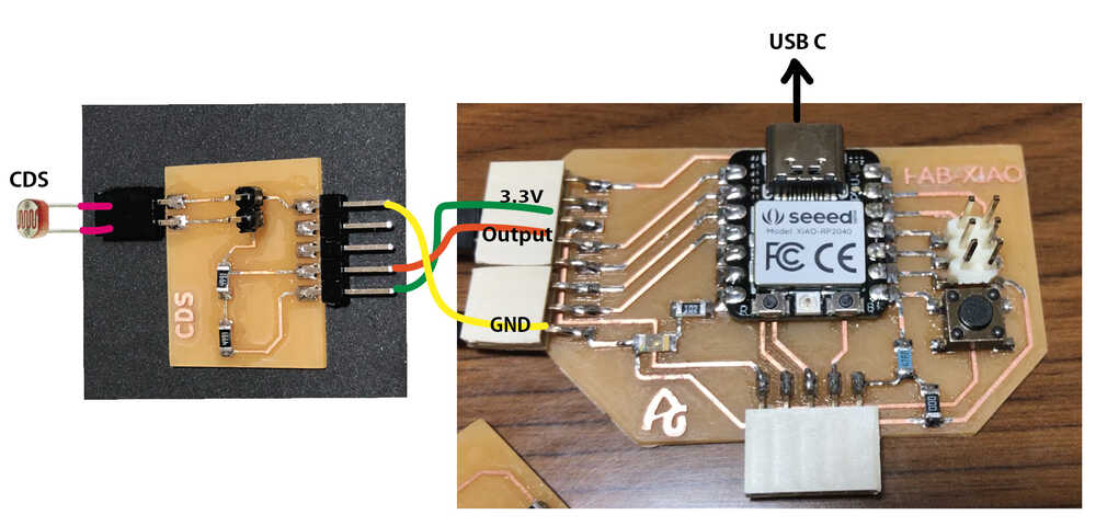
 I made Fab-Xiao RP2040 board by Adrian.
Then, I connect as follows.
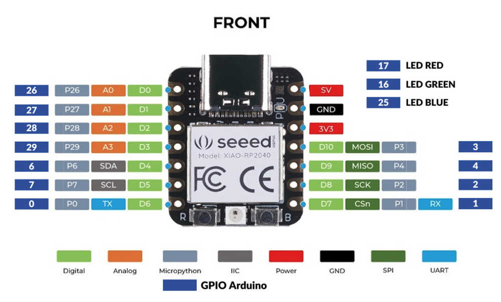
Pinout in Fab-Xiao by Ardian Torres site.
Arduino IDE use GPIO Arduino
3. Programming
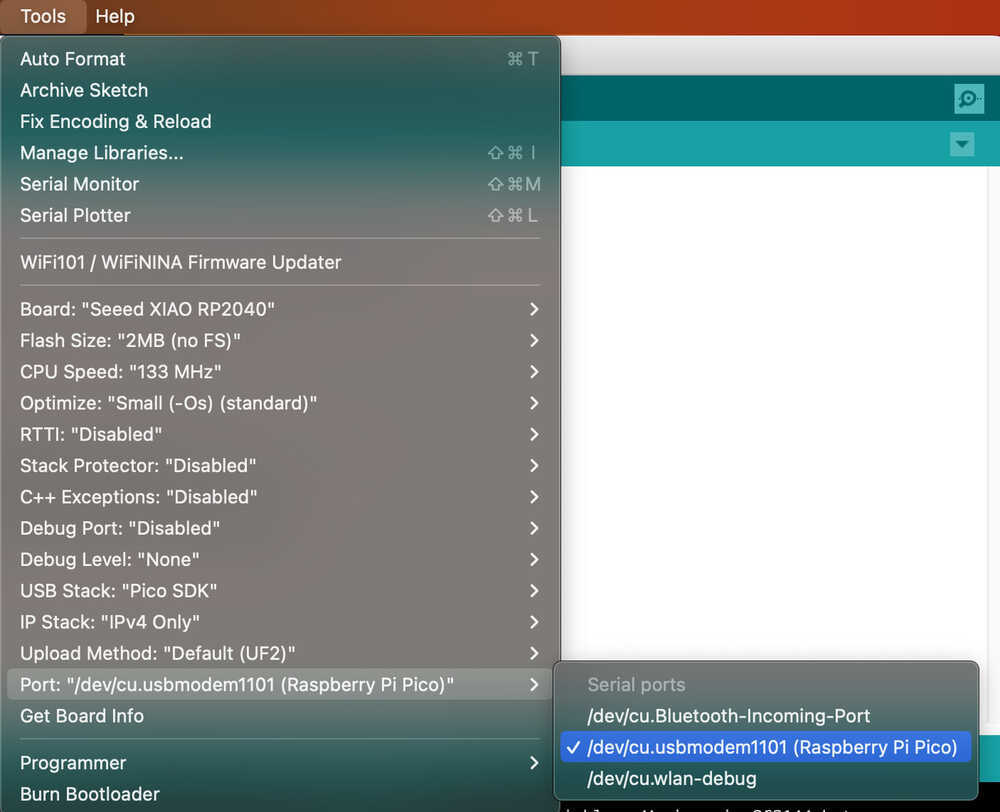
- I open Arduino IDE and choose Board "Seeed XIAO RP2040".
- I confirm the Port appeared. In this time, my Port is "/dev/cu.usbmodem1101".
- I input each Programming code to Arduino IDE and Processing. In this time, I use Adrian's Fab-Xiao Phototransistor code.
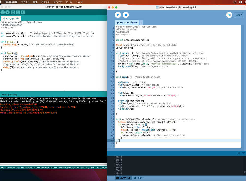
3-1) Code for Arduino IDE
I use Adrian's Fab-Xiao Phototransistor code for Arduino IDE.
//Fab Academy 2023 - Fab Lab León
//Phototransistor
//Fab-Xiao

int sensorPin = A0;    // analog input pin RP2040 pin 26 or ESP32-C3 pin A0
int sensorValue = 0;  // variable to store the value coming from the sensor

void setup() {
  Serial.begin(115200); // initialize serial communications
}

void loop() {
  sensorValue = analogRead(sensorPin); // read the value from the sensor
  sensorValue = map(sensorValue, 0, 1024, 1024, 0);
  Serial.println(sensorValue); // print value to Serial Monitor
  //mySerial.println("x"); // print value "x" to Serial Monitor
  delay(50); // short delay so we can actually see the numbers
}
3-2) Code for Processing
I input Adrian's Fab-Xiao Phototransistor code for Processing, and change Port to mine. In my case, Port is "/dev/cu.usbmodem1101".
//Fab Academy 2020 - Fab Lab León
//Phototransistor
//Adrianino
//ATtiny1614

import processing.serial.*;

float sensorValue; //variable for the serial data
Serial myPort;

void setup() {  //as dynamic/setup function called initially, only once
  size(1024, 200);// is the window (1024=sensor max. value)
  //replace the port String with the port where your Arduino is connected
  //myPort = new Serial(this, "/dev/tty.wchusbserial1450", 115200);
  myPort = new Serial(this, "/dev/cu.usbmodem1101", 115200); // serial port
  background(255);  //set background white

}

void draw() {  //draw function loops

  noStroke(); // outline
  fill(255,0,0,20); // color inside
  rect(0, 0, sensorValue, height); //position and size

  fill(255,70);
  rect(sensorValue, 0, width-sensorValue, height);

  println(sensorValue);
  fill(0,0,0);// these are the colors inside
  text(sensorValue + " " + "cm" , sensorValue, height/2);
  textSize(32);

}

void serialEvent(Serial myPort) { // sketch read the serial data
  String inString = myPort.readStringUntil('\n');
  if (inString != null) {
    inString = trim(inString);
    float[] values = float(split(inString, ","));
    if (values.length >=1) {
      sensorValue = values[0]; //first value in the list
    }
  }
}
4. Video
Result, as below Video shows, I added CDS to a board I designed and read it to Fab-Xiao RP2040. I could see the CDS sensor value using Arduino IDE and Processing.