- TRY Blynk
This page is the process for TRY "Blynk".
I tried control LED Pin 2 (GPIO pin 2) on ESP32 board that I designed by week09 with browser, using Blynk.
I studied Blynk and watched youtube: hitunodsnpo (Japanese), then start it.
1. What is Blynk?
- Low-Code IoT Software Platform for Electronics Manufacturers
- Here is what you need to Blynk (As of 6-May, 2023)
- A smartphone
- Internet Connection
- WiFi, Ethernet, Cellular (GSM, 2g, 3g, 4g, LTE), Serial, USB via your PC, Bluetooth (BETA)
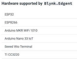
- IoT Hardware as following
2. IDE and board I used.
- ESP32 board that I designed by week09
- Arduino IDE
3. How I used Blynk
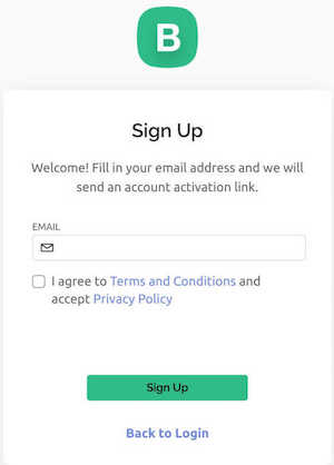
- Register my account on Blynk
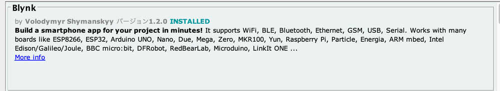
- Open Arduino IDE, I installed Blynk Library
- Connect hardware
- Setting Blynk (The details below)
4. PC setting
In PC, login Blynk
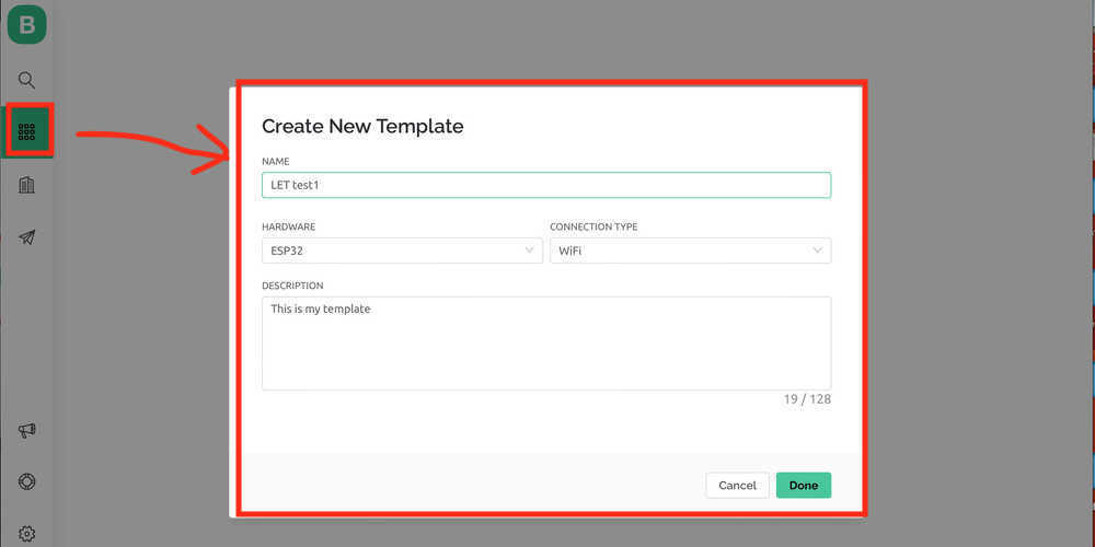
- Create Template
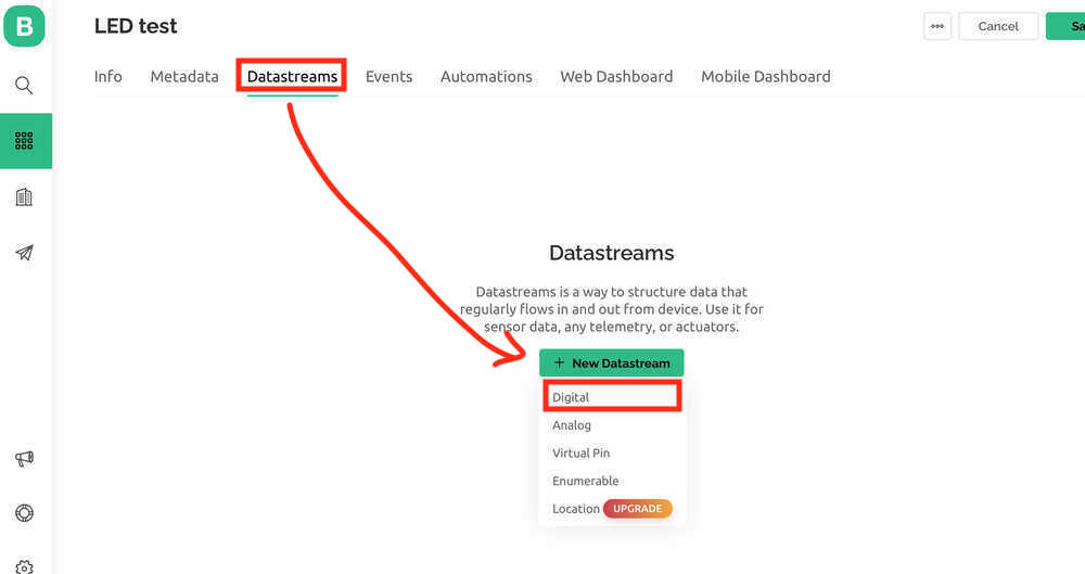
- Datastreams:
Setting the details from Blynk to each target device.- In this time, I choose Digital
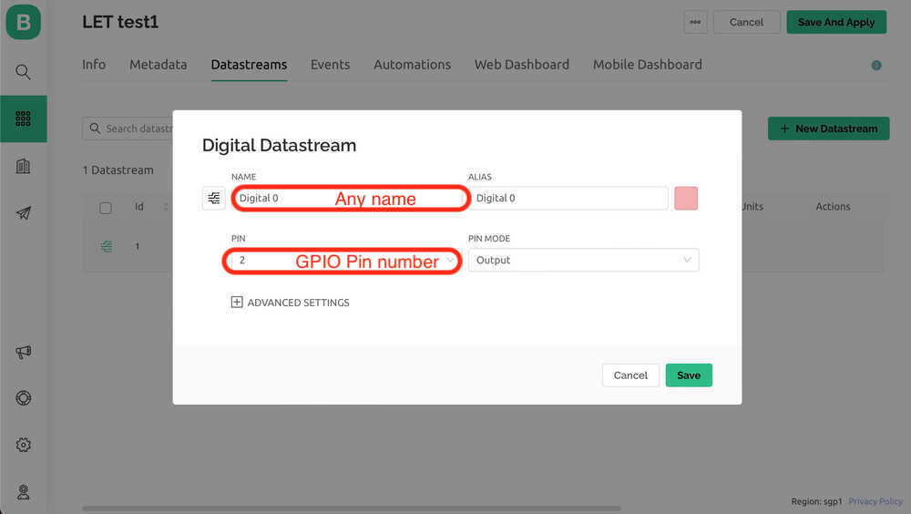
- Setting for LED
- Name: Any name is OK.
- PIN: 2 (For PIN, enter the GPIO number from the datasheet.)
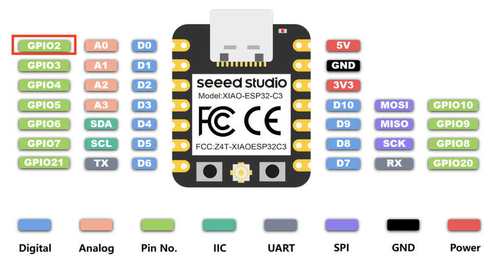
Pinout of XIAO ESP32C3 from Datasheet
XIAO ESP32C3 Board that I made in Week09.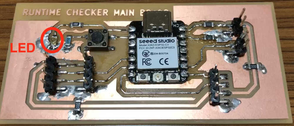
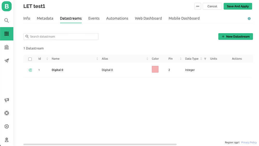
- In this time, I choose Digital
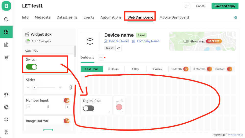
- Web Dashboard
- Drag the Widget(switch and LED) to Dashboard and setting
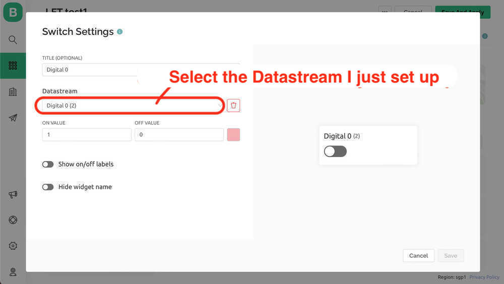
- Switch Settings details
- LED Settings details
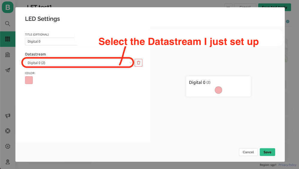
- Drag the Widget(switch and LED) to Dashboard and setting
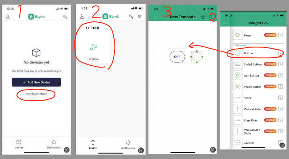
5. Smartphone setting
Install Blynk App (Only the first time).
Then, Login Blynk App.
- Select "Developer Mode".
- Choose template I made in PC. (-> Edit view of Dashboard is opened.)
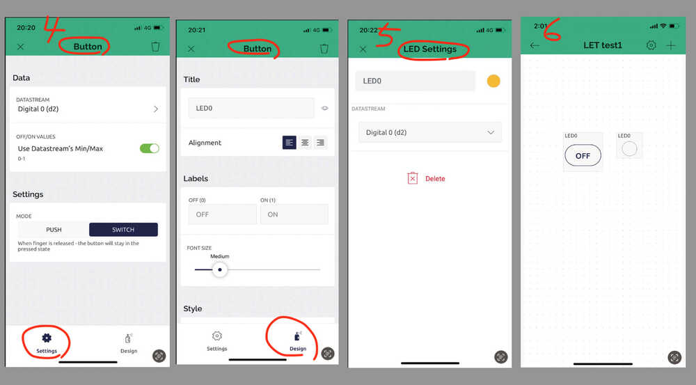
- Add Button and LED. (Button is a alternative of switch )
- Click Button and setting.
- Click LED and setting.
- Once the buttons and LEDs are tied to the pins configured on the PC, the setup is complete.
6. Create a new device / Auth Token
- Return to the Blynk' management page in PC to work again.
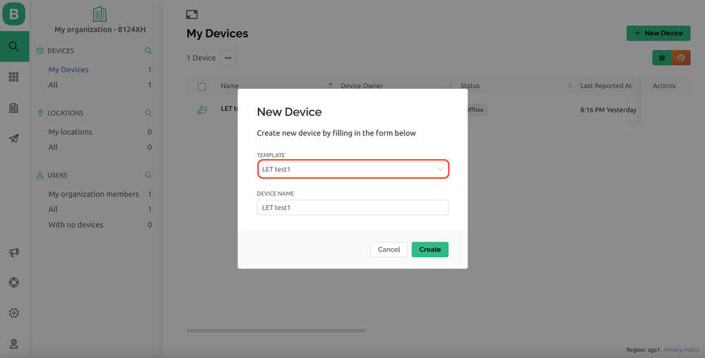
- Create a new device from template.
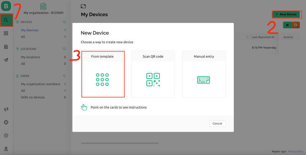
- Choose template.
- Auth Token is appeared.
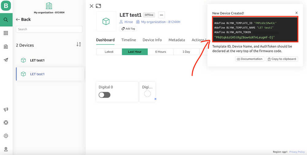 In order for Blynk to communicate with each target device, an Auth Token must be planted on the target device side.Copy this AuthToken and insert it into the Arduino IDE code.
7. Arduino IDE
- Open Arduino IDE
- choose board "XIAO_ESP32C3", Port is "/dev/cu.usbmodem1101" in this time.
- upload the code
Code for Arduino IDE
- the citting code from hirunosannpo.blog.jp
- Replace AuthToken, Lines 7-9.
/*************************************************************
  This is a simple demo of sending and receiving some data.
  Be sure to check out other examples!
 *************************************************************/
// Template ID, Device Name and Auth Token are provided by the Blynk.Cloud
// See the Device Info tab, or Template settings
#define BLYNK_TEMPLATE_ID "TMPL6OcSMw4Jc"
#define BLYNK_TEMPLATE_NAME "LET test1"
#define BLYNK_AUTH_TOKEN "PRdtqk6zGHSiRgZ8ow4sNTmLeugmF-Oj"

// Comment this out to disable prints and save space
#define BLYNK_PRINT Serial

#include <WiFi.h>
#include <WiFiClient.h>
#include <BlynkSimpleEsp32.h>
#include <math.h>

char auth[] = BLYNK_AUTH_TOKEN;

// Your WiFi credentials.
// Set password to "" for open networks.
char ssid[] = "your wifi id";
char pass[] = "your wifi password";

BlynkTimer timer;

// the number of the LED pin (GPIO number)
const int ledPin = 2;

// This function is called every time the Virtual Pin 1 state changes
BLYNK_WRITE(V1) ///LightPin:Relay_operates_on_LOW_Input_Voltage_coneccted_NC
{
  int buttonState = param.asInt();
  // Update state
  if(buttonState == HIGH){
     digitalWrite(ledPin, HIGH);
     Serial.println("HIGH");
  }else{
     digitalWrite(ledPin, LOW);
     Serial.println("LOW");
  }
}

// This function is called every time the device is connected to the Blynk.Cloud
BLYNK_CONNECTED()
{
  Serial.println("Connected!");
}
//////////////////////////////////////////////////////////////////////

void setup() {
  // Serial port for debugging purposes
  Serial.begin(115200);

  //pinMode setting
  pinMode(ledPin , OUTPUT);

  //WiFI Setting
  Blynk.begin(auth, ssid, pass);
  // You can also specify server:
  //Blynk.begin(auth, ssid, pass, "blynk.cloud", 80);
  //Blynk.begin(auth, ssid, pass, IPAddress(10,0,1,28), 8080);
  //Blynk.begin(auth, ssid, pass, IPAddress(10,0,1,28));

  // Setup a function to be called every second
  //  timer.setInterval(1000L, myTimerEvent);
}

void loop() {
  Blynk.run();
}
As a result, I could control LED on/off with Blynk and PC Browser, and smartphone (4G).