- Fusion (Model & Tool Path)
This is the page of Process for the individual assignment of Week7.
It is time to design. It is important to consider clearance with the results of the "kerf test" in Group work. And It is also important that CNC end mills create clearance holes in the seams.
1. Model
Fusion360 (->DESIGN)
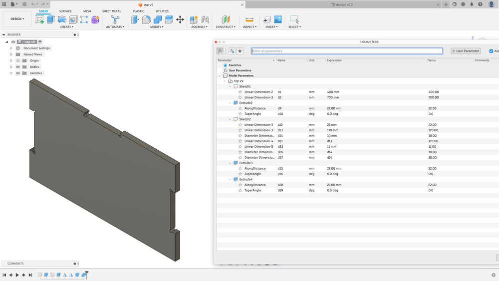
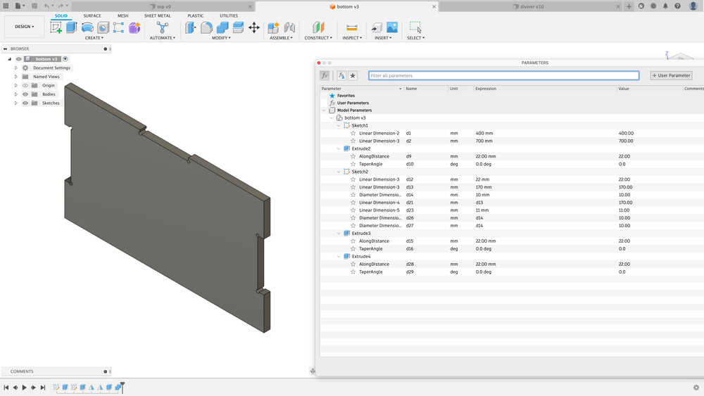
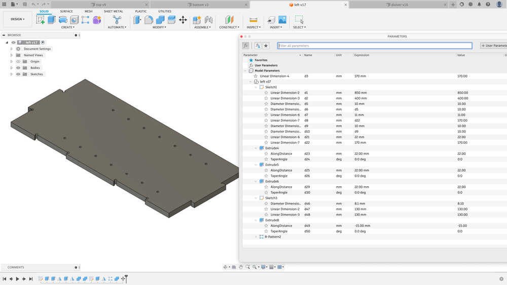
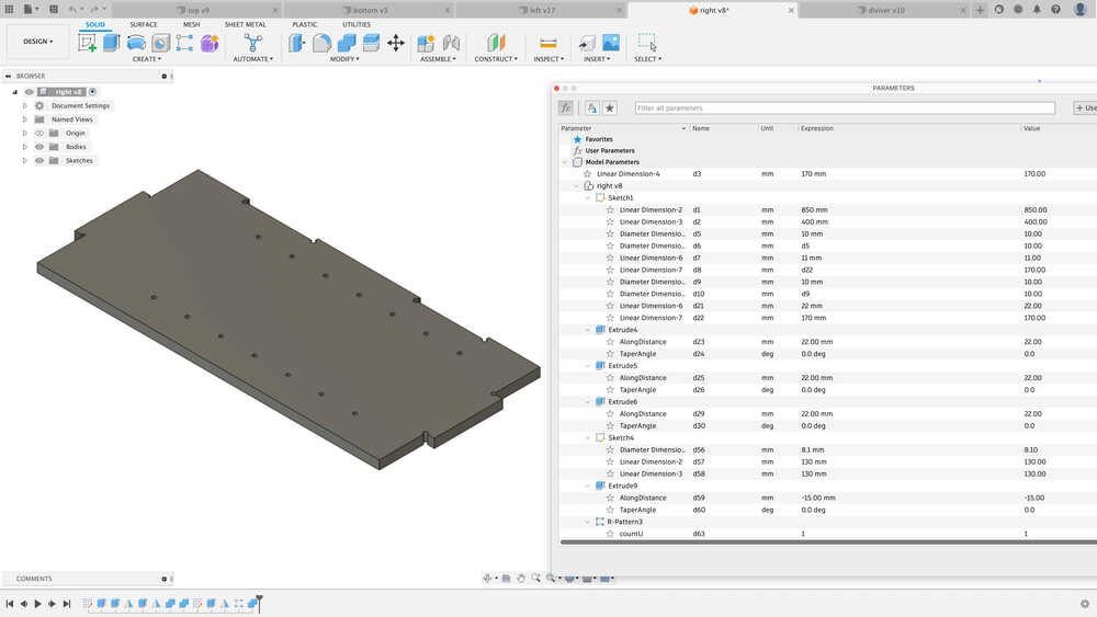
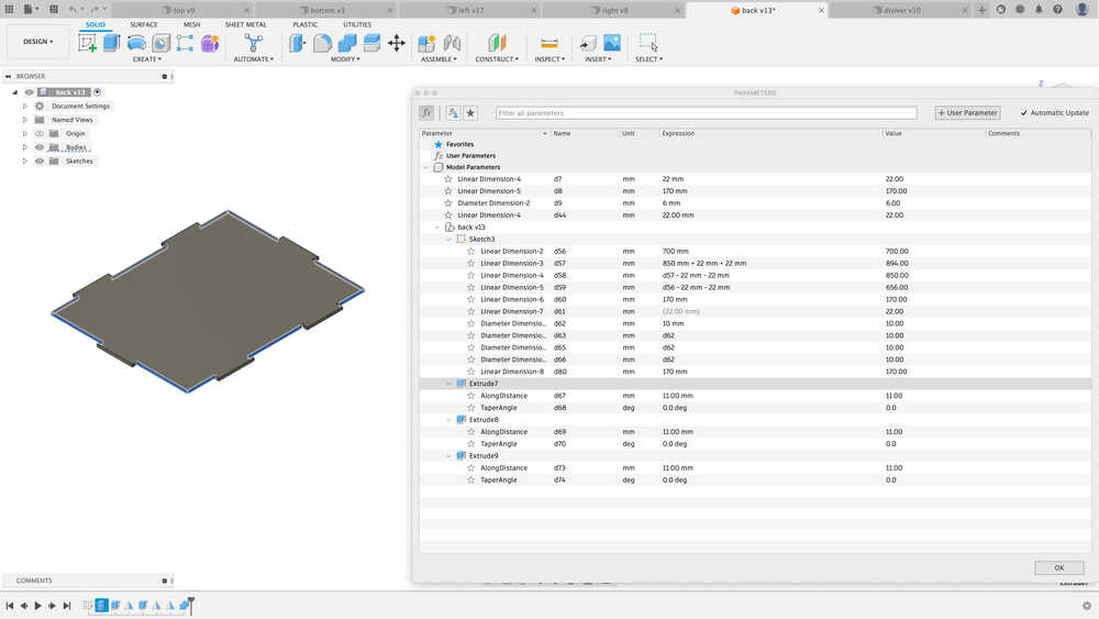
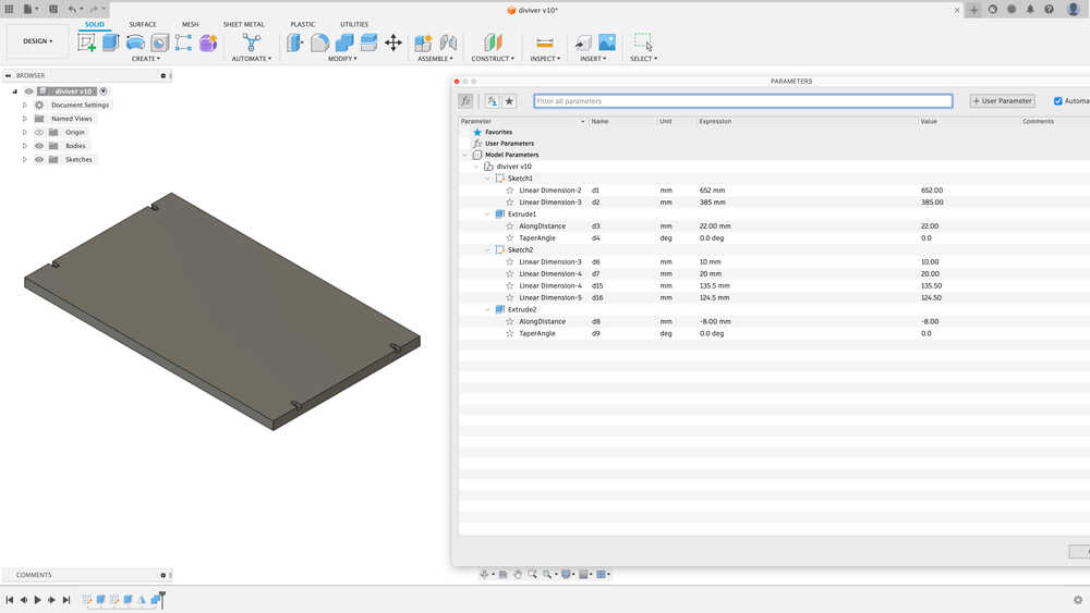
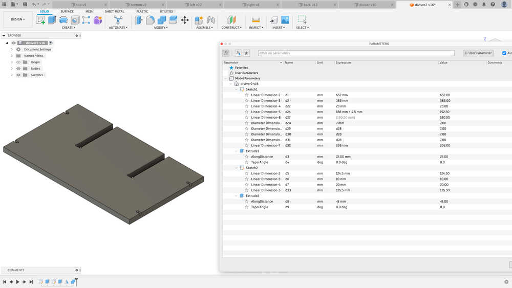
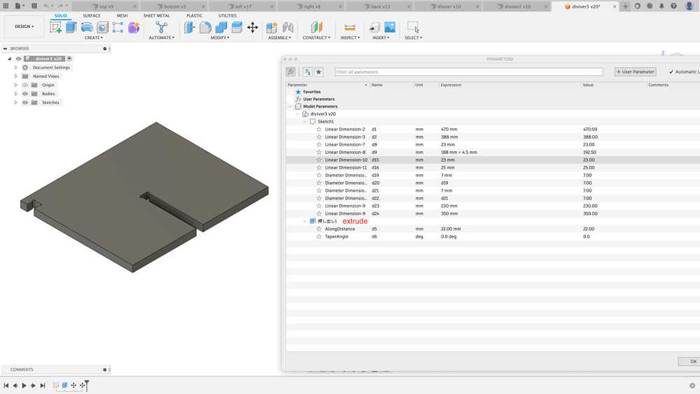
- I made each Parts Design, as following.
- Top board
- Bottom board
- Left board
- Right board
- Back board
- Divider1
- Divider2
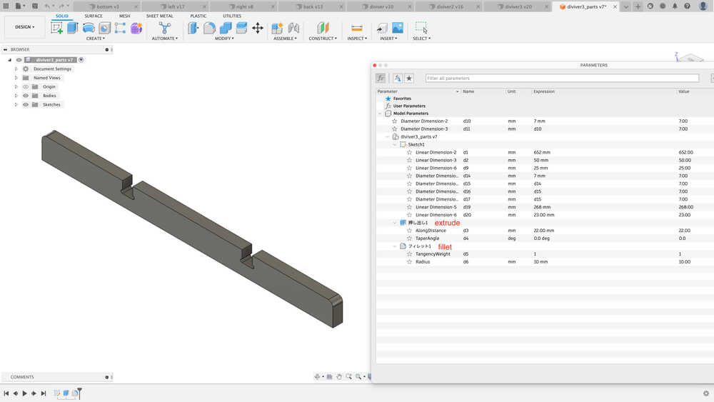
- Divider3
- Divider3_parts
2. Assemble & Section Analysis
Fusion360 (->DESIGN)
- It would be difficult to match joint, so I used Assemble in Fusion360 to check the joint of each part as we created it.
- Assemble is very hard time as I am not get used to do it.
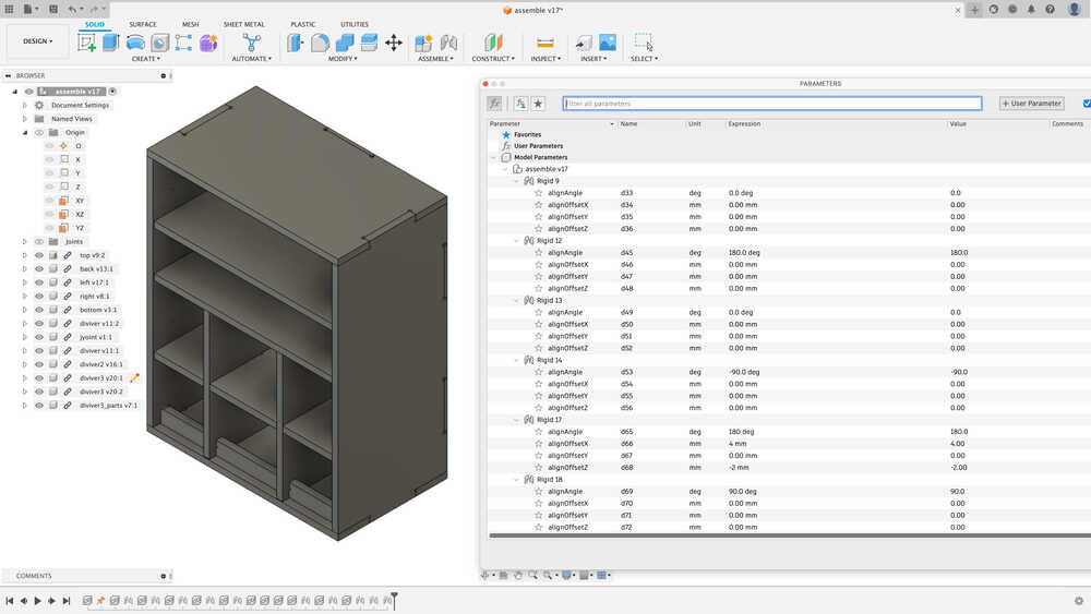
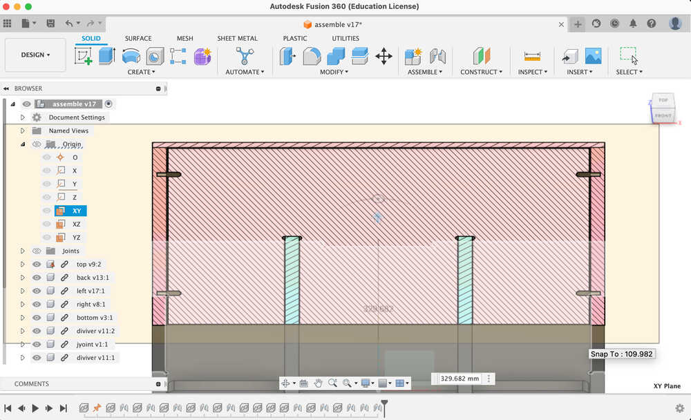
- Section Analysis
In the file of Assemble, I do section analysis. It is useful tool to check the clearance with XY plane and XZ plane and YZ plane. With section analysis, I found there was an interference point. So I solve the problem that I modified the design and reconfirm with section analysis.
3. create file for tool path
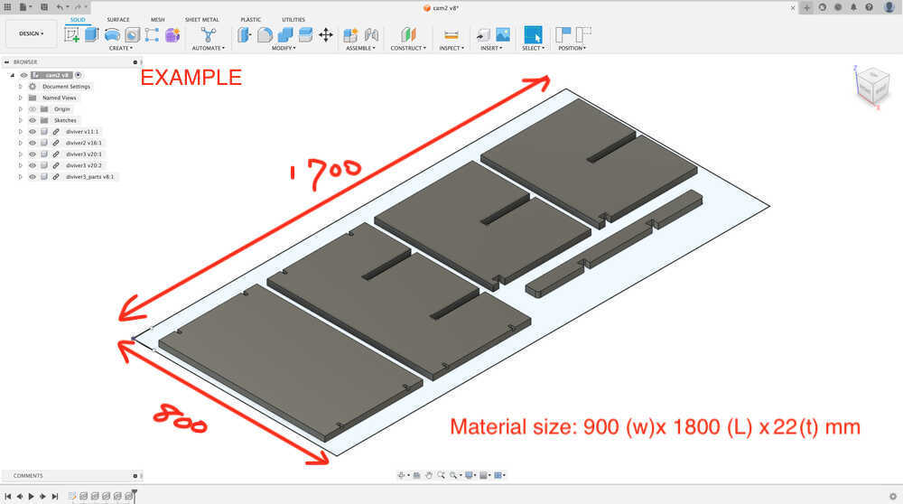
For safety reasons, the area of the fixing and the area of the part layout should be clearly defined. Parts Layout Area (Orange area) should offset by -50mm or more from the stock outline size.
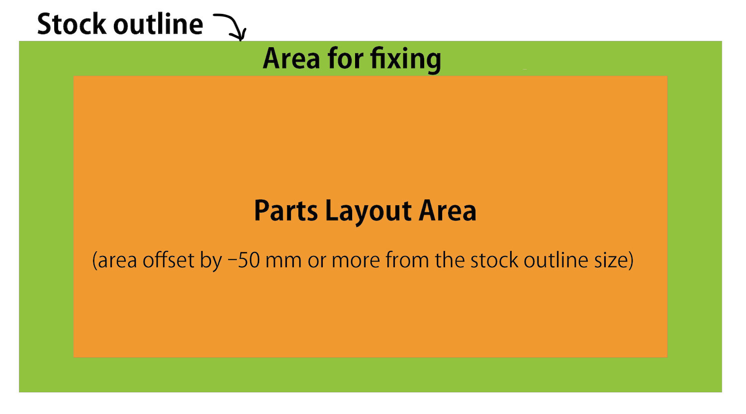
For example, In the fusion360, I made orange area using a square, and layout the parts in the area.
Finish the design, and it's time to create tool paths.
4. Tool paths
Fusion360 (->MANUFACTURE)
4-1) Setup
-
Setup
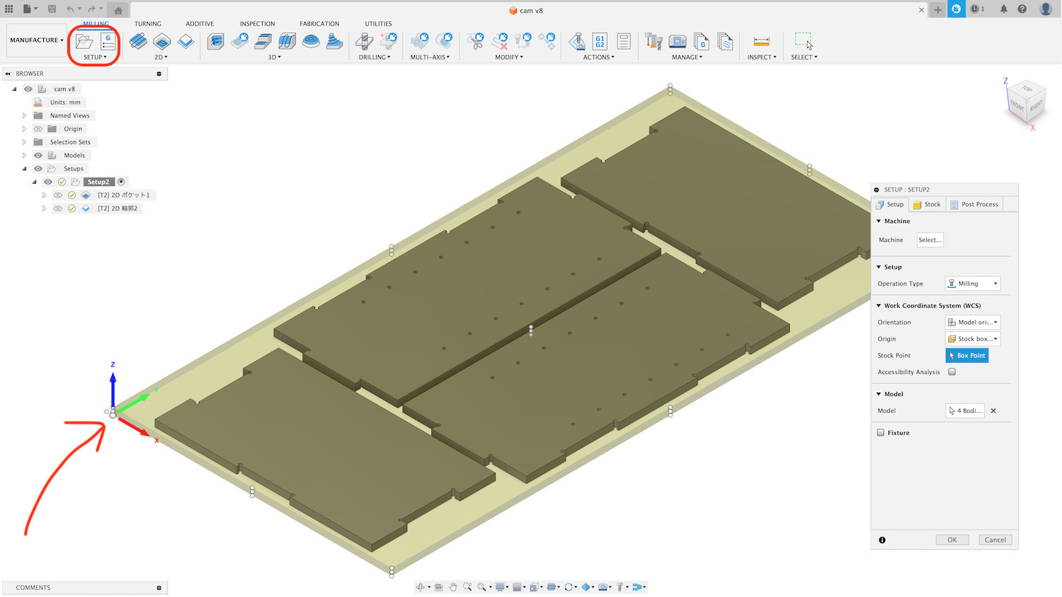
- Machine: NO setting
- Operation Type: Milling
- Work Coordinate System (WSC)
- Orientation: (Default)
- Origin: (Default)
- Stock point (Box point)-> setting XYZ0 point (in my case, choose material bottom)
NOTE**: Stock point is important, the miss choose connect to accident. - Model (Select Body)
-
Stock setting
- Mode: (Default)
- Stock Offset Mode :Add stock to sides and top-bottom
input -X, ;X,-Y,;Y , about material margin size around the model
Then confirm Dimensions of the material area.
-
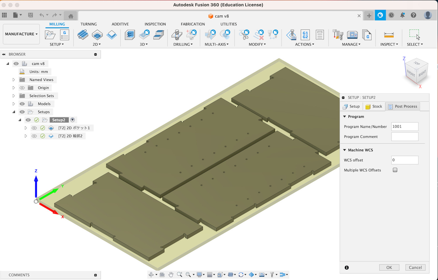
Post-processing: (default)
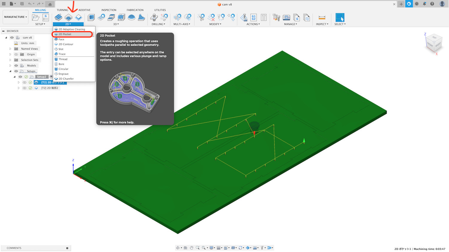
Now it's time to create the path for 2D pocket. Create a tool path for a non-penetrating hole.
4-2) Tool path (2D pocket)
-
Tool
- Tool Library-> Local (right click > Turn on All libraries on)
- Choose mill (Flat end mill, Diameter 6mm :In this time ) and save.
- Edit tool of "Flat end mill 6mm"
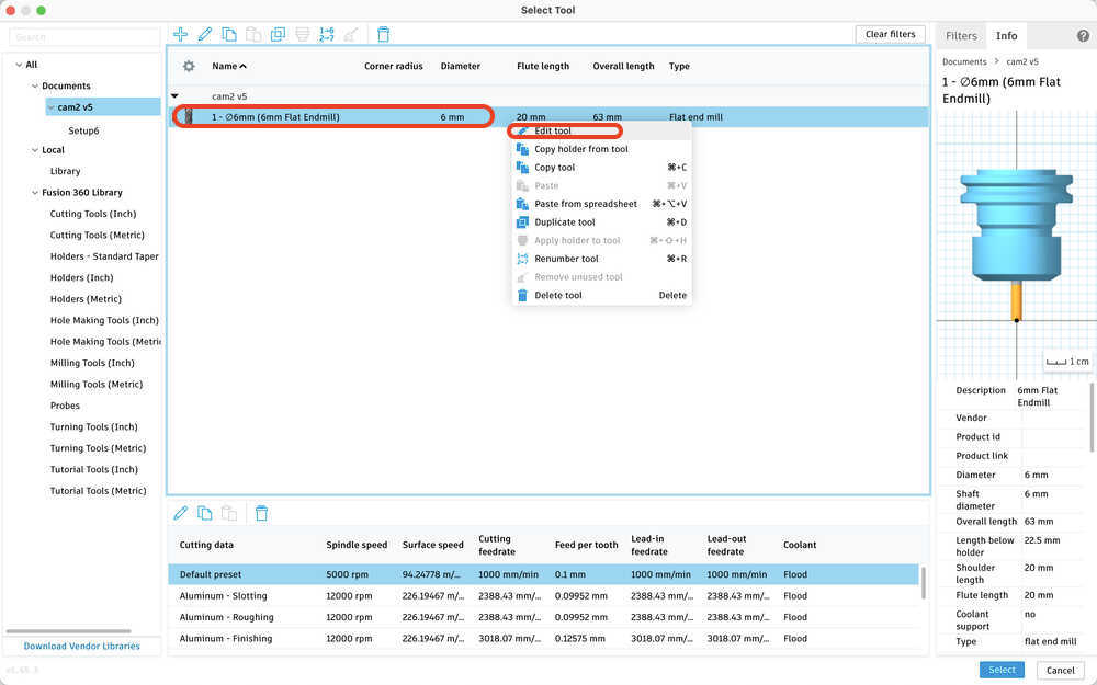
change flutes: 2 (-> In this time, we use flutes 2)
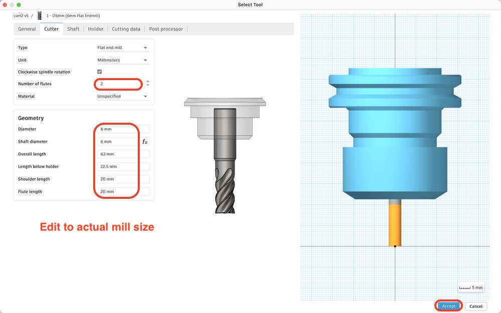
NOTE:
If the tool is Luffing End Mill, select "flutes: 4" - Material : Carbide - Geometry: Measure and correct the mill for actual use. Material thickness is also relevant. Must select a mill with a length that can be cut - The rest is default
-
Coolant: Disabled
-
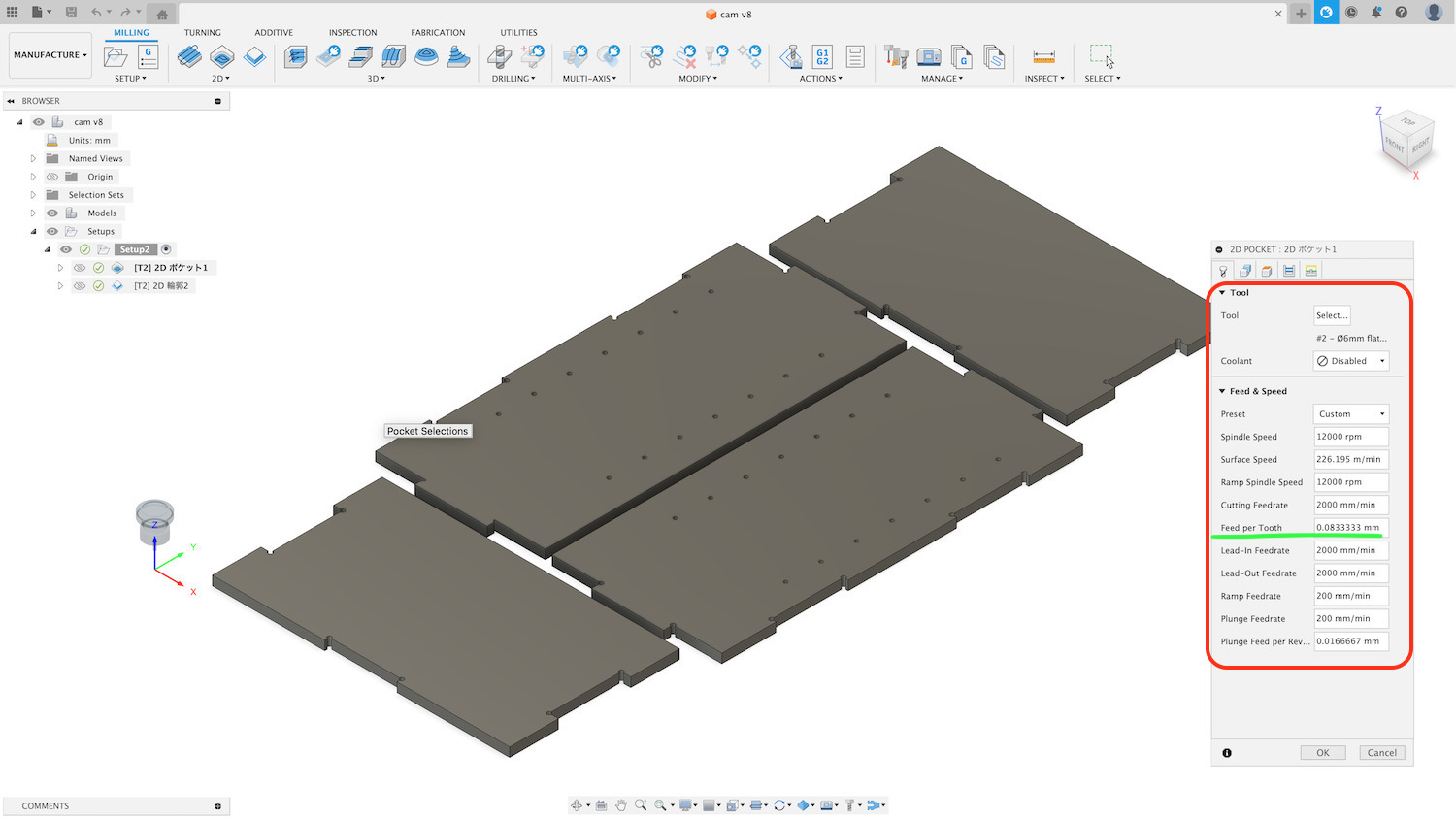
Feed & Speed
- Spindle Speed:12000 rpm
- Ramp Spindle Speed:12000 rpm
- Cutting Feedrate: 1200mm/min <- 1st cut, 2000 mm/min <- 2nd cut
- Feed per Tooth:
- 0.05 <- 1st cut(0.01-0.05 @FabLab West harima recommend)
- 0.083 <- 2nd cut (this material is soft, so it it OK the value, confirm to @FabLab West harima )
- Lead-In Feedrate: 1200 mm/min <- 1st cut, 2000 mm/min <- 2nd cut
- Lead-Out Feedrate: 1200mm/min <- 1st cut, 2000mm/min <- 2nd cut
- Range Feedrate : 1200mm/min <- 1st cut, 2000mm/min <- 2nd cut
- Ramp Feedrate 200mm/min - 300mm/min (Default)
- Plunge 100mm/min - 200mm/min <- check( @FabLab West harima recommend)
-
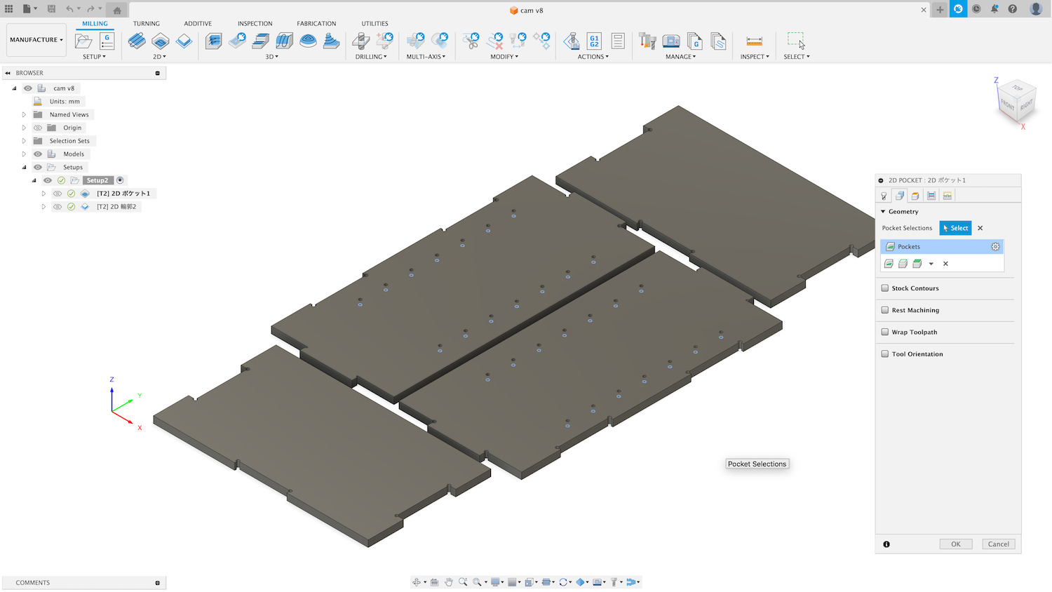
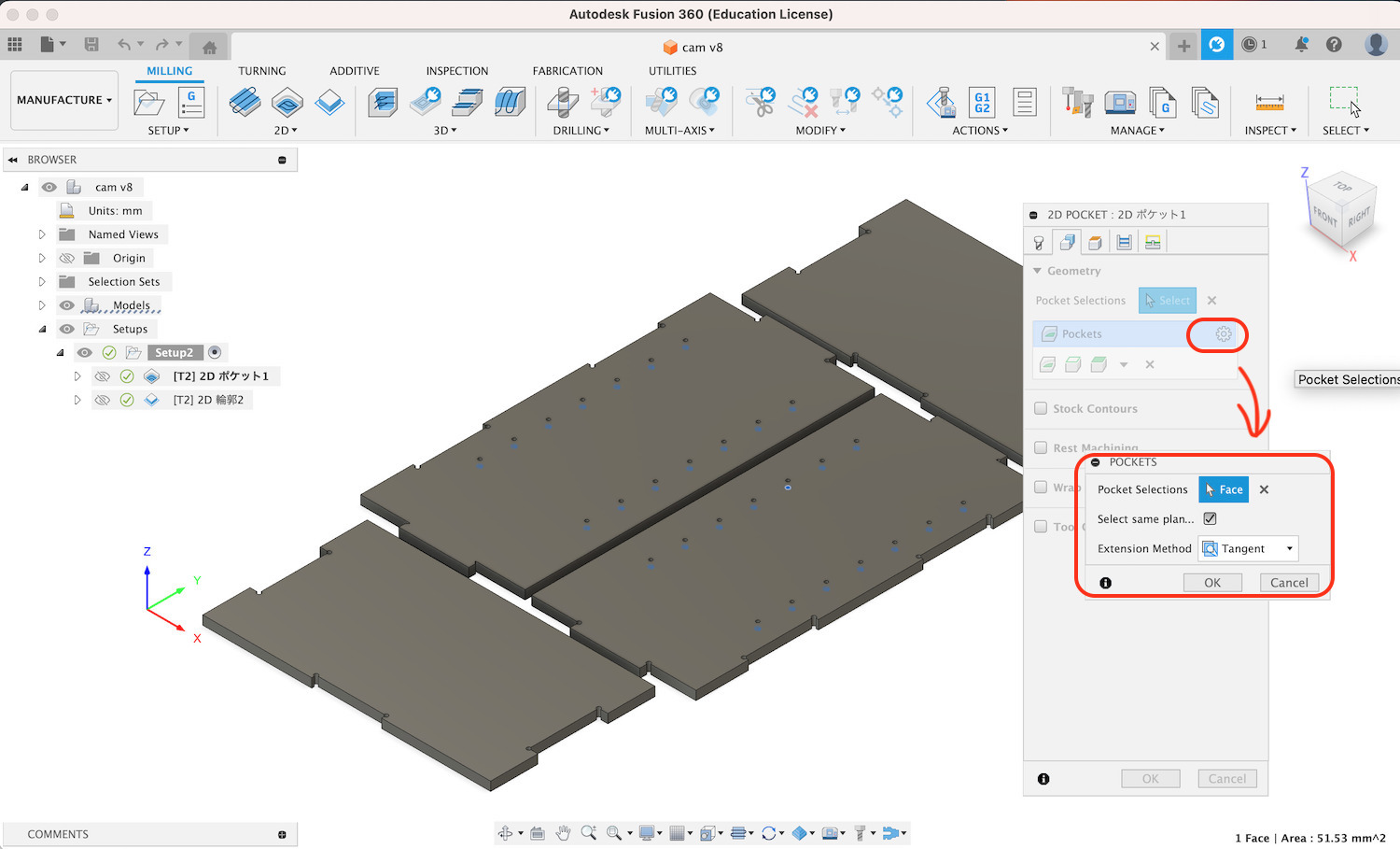
Geometry
Select bottom of Pocket. Check "Select same plane"
-
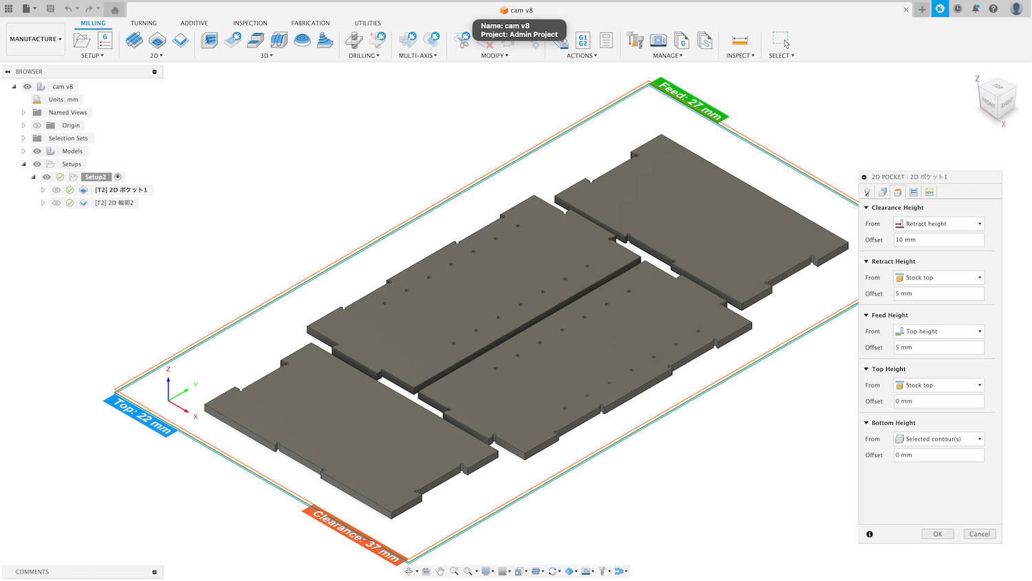
Heights (Travel Height)
If you are not sure, use the default
-
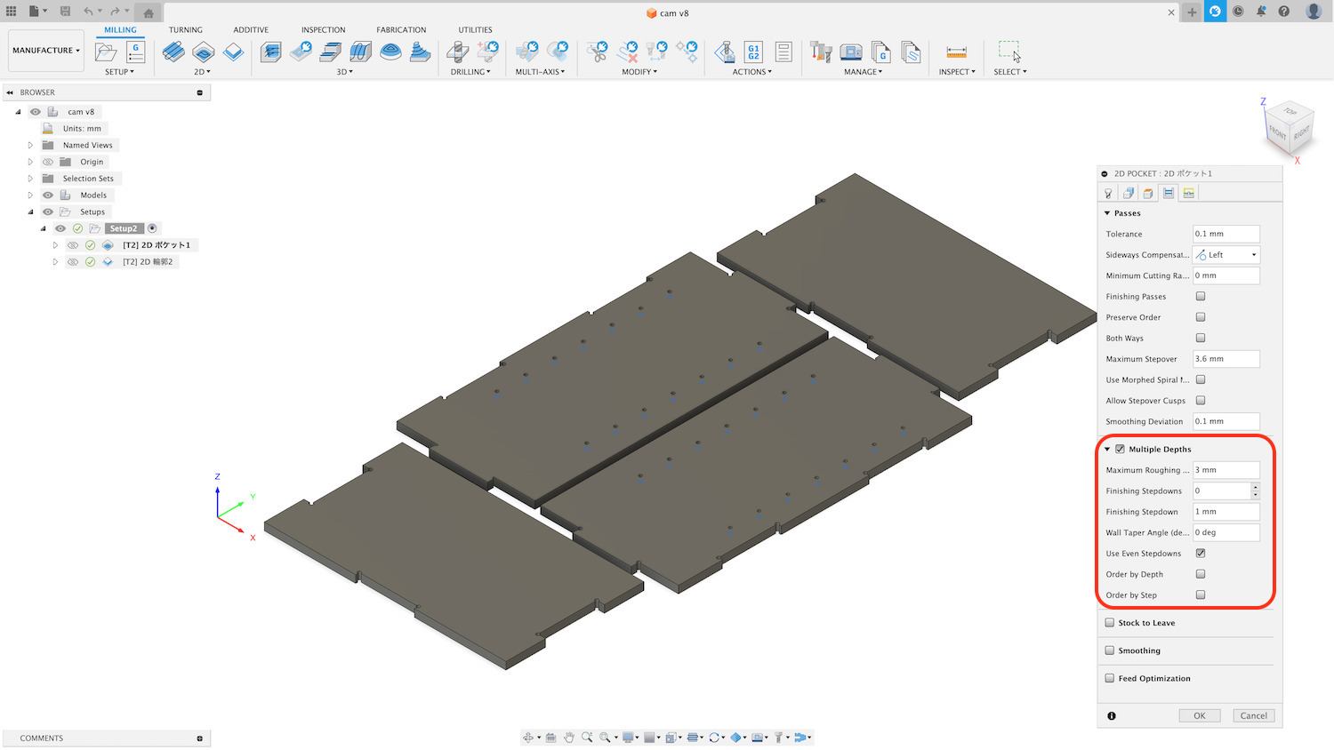
Passes
- Multiple Depths:
In this time, select 3mm (The tool used this time is a flat end mill with a diameter (D) of 6 mm, so we set the pitch to 3 mm.) - Finishing Stepdown: 1mm (Not required due to pocket processing, but 0 cannot be input, so input changed to 1.)
- Multiple Depths:
-
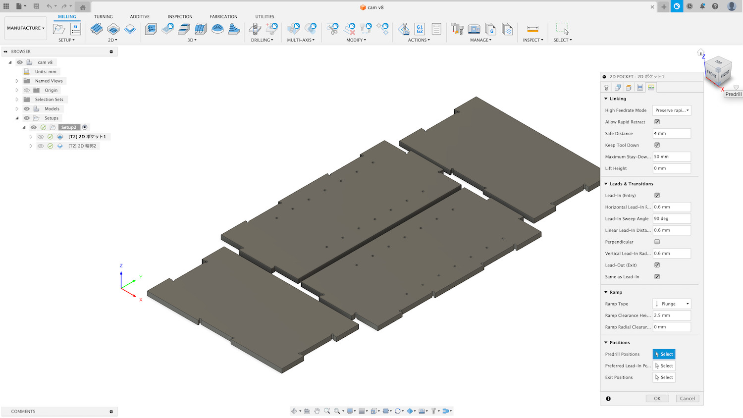
Linking / Leads & Transitions / Ramp / Positions
If you are not sure, use the default
-
Action > Generate
- Path generated
- If path is not generated, an error message is displayed
-
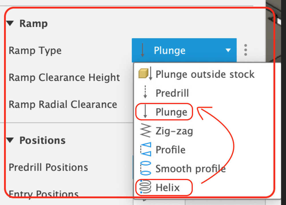
Error by default
- Alert on Ramp type Helix (min. ramp diameter 3 mm, radius 1.5 mm)
- Status:8.1mm diameter hole, End mill 6mm (radius 3mm)
- Result: Helix can only drill a 9mm diameter hole.
Since the hole size cannot be changed, the ramp type was changed to "Plunge".
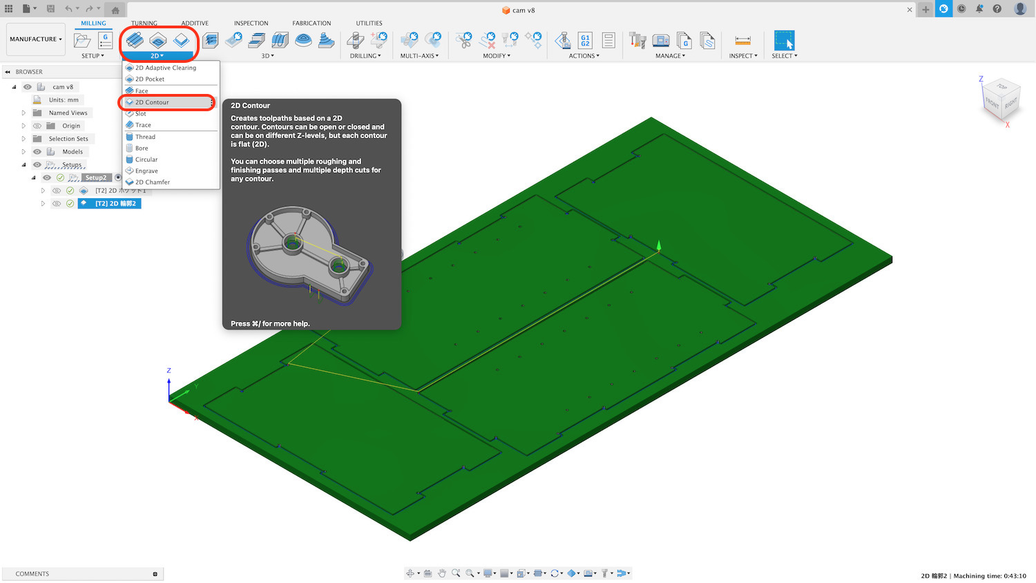
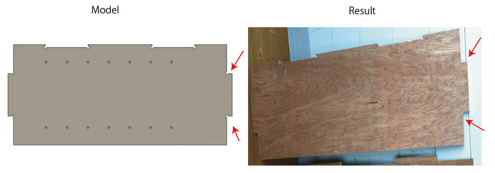
Now it's time to create the path for 2D Contour. Creates a tool path around the perimeter of the model, etc. Note that forgetting to create tabs at this time will cause parts to fly off, with check the important point.
4-3) Tool path (2D Contour)
-
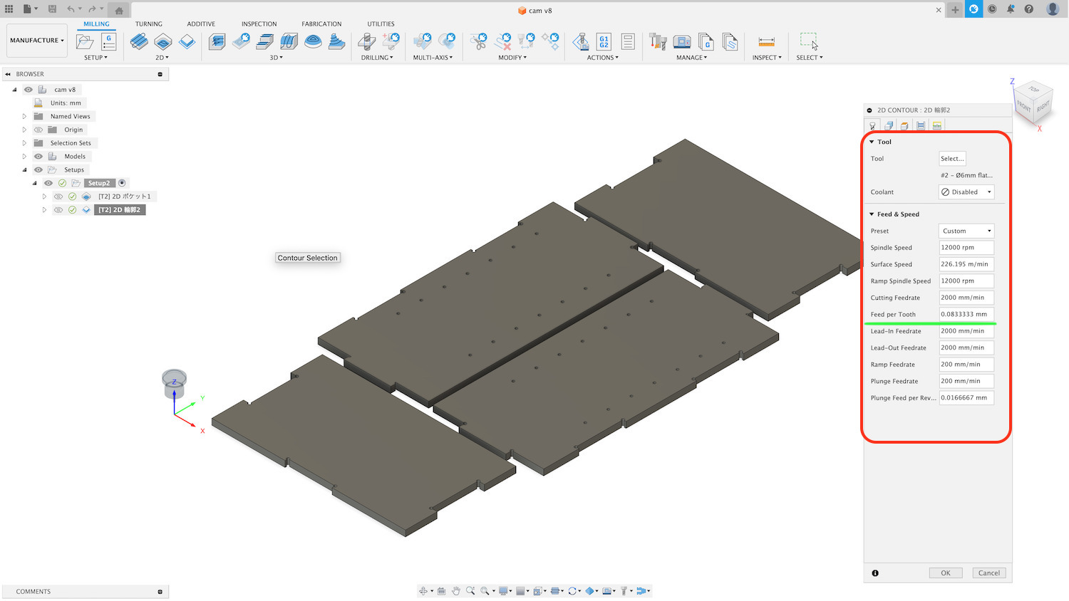
Tool
- Tool: Select Flat end mill diameter 6mm (flute 2)
- Coolant: Disabled
-
Feed & Speed
- Spindle Speed:12000 rpm
- Ramp Spindle Speed:12000 rpm
- Cutting Feedrate: 1200mm/min <- 1st cut, 2000 mm/min <- 2nd cut
- Feed per Tooth:
- 0.05 <- 1st cut (0.01-0.05 @FabLab West harima recommend)
- 0.083 <- 2nd cut (this material is soft, so it it OK the value, confirm to @FabLab West harima )
- Lead-In Feedrate: 1200 mm/min <- 1st cut, 2000 mm/min <- 2nd cut
- Lead-Out Feedrate: 1200mm/min <- 1st cut, 2000mm/min <- 2nd cut
- Range Feedrate : 1200mm/min <- 1st cut, 2000mm/min <- 2nd cut
- Ramp Feedrate: 200mm/min - 300mm/min (Default)
- Plunge 100mm/min <- check(100mm/min @FabLab West harima recommend)
-
Geometry
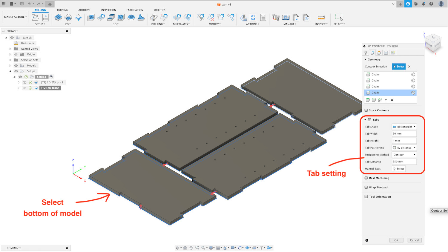
- Select the bottom of model
-
Tab setting: Tab width 20 mm, Tab height 4mm, Tab Distance 210mm
- For 2D Contour, set tabs so that material is not cut away. For safety reasons, the number of tabs was set so that each part has at least 4 points. The tab height followed the instructions at FabLab West-harima.
-
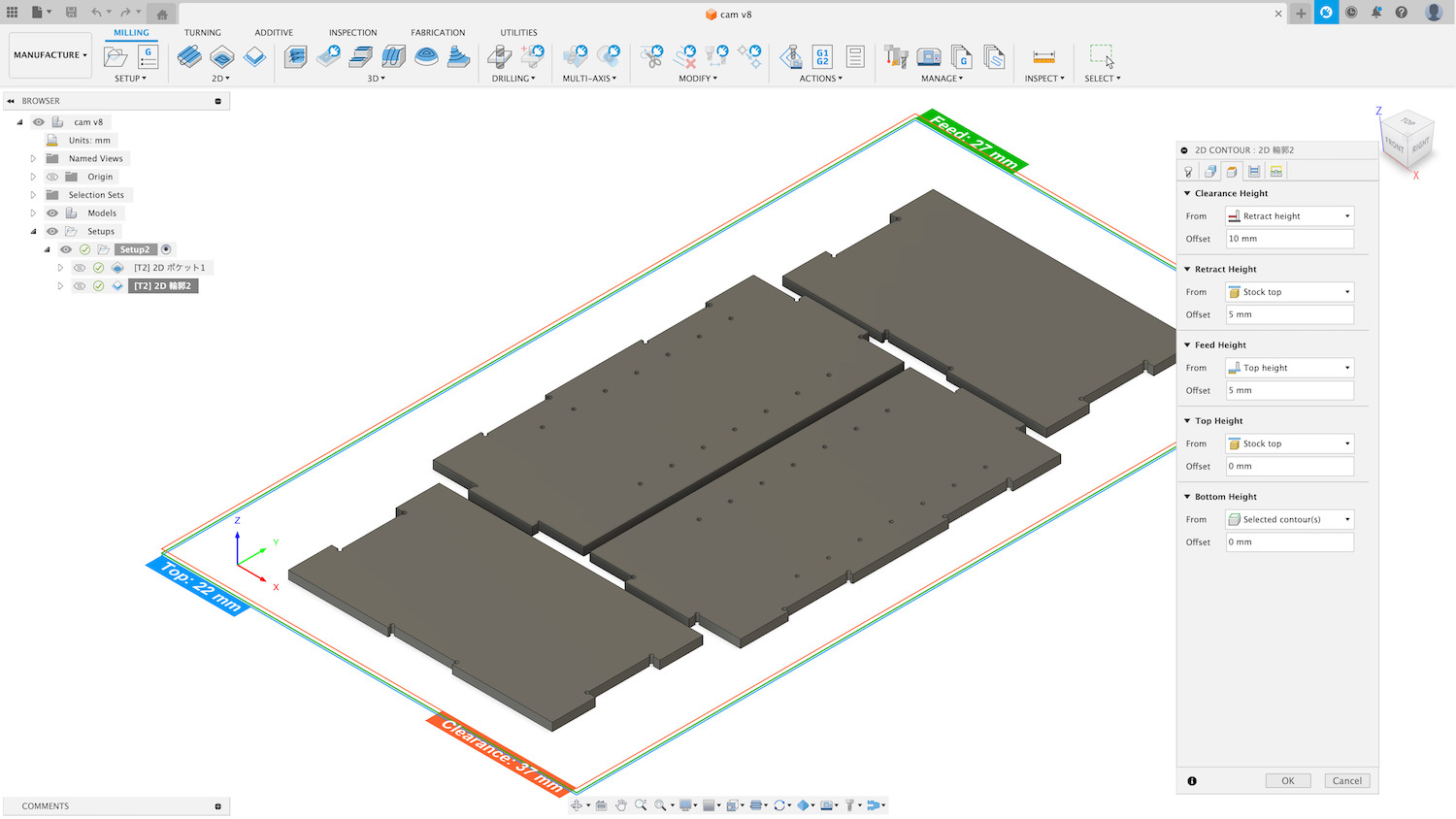
Heights (Travel Height)
If you are not sure, use the default
-
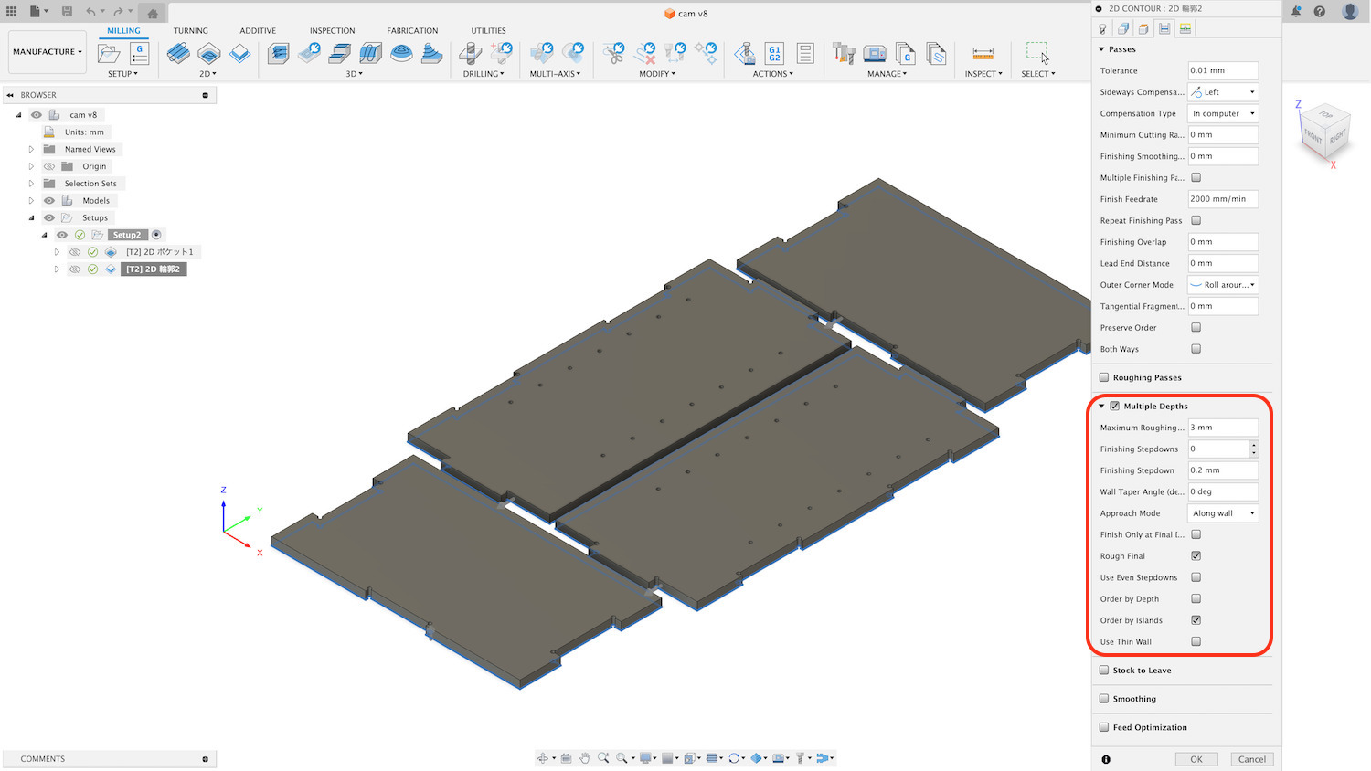
Passes
- Multiple Depths In this time, select 3mm (The tool used this time is a flat end mill with a diameter (D) of 6 mm, so we set the pitch to 3 mm.)
- Finishing Stepdown: 0.2mm
- Others: Default
-
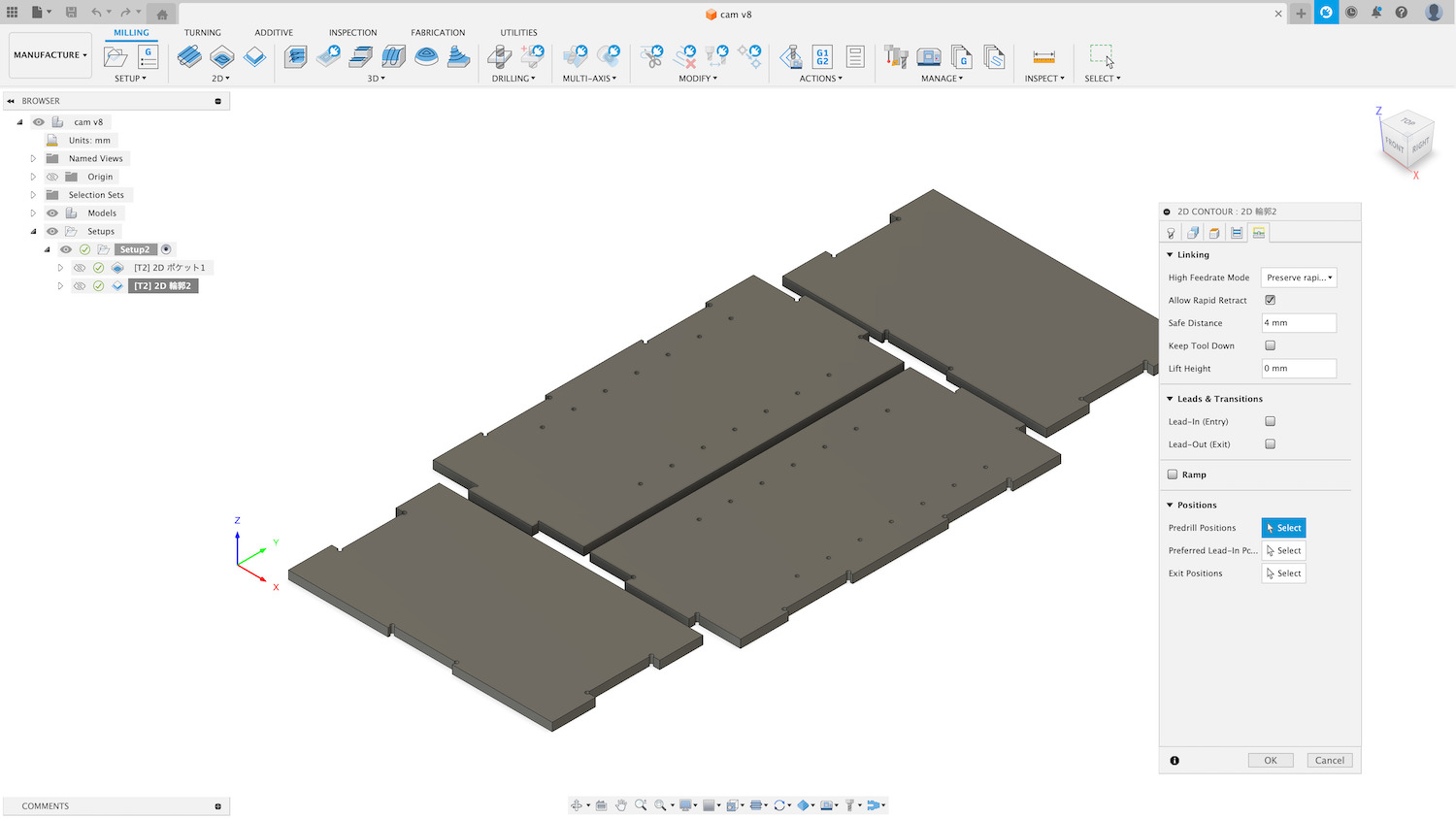
Linking
If you are not sure, use the default
4-4) Generate
Action > Generate
4-5) Dogbone
I designed the dogbone, forgot the Instructor's advice and designed it incorrectly. The dogbone entrance width was narrower than the end mill diameter, and when I generated the path, the dogbone shape was excluded from the cutting point. It is important to make dogbone correctly.
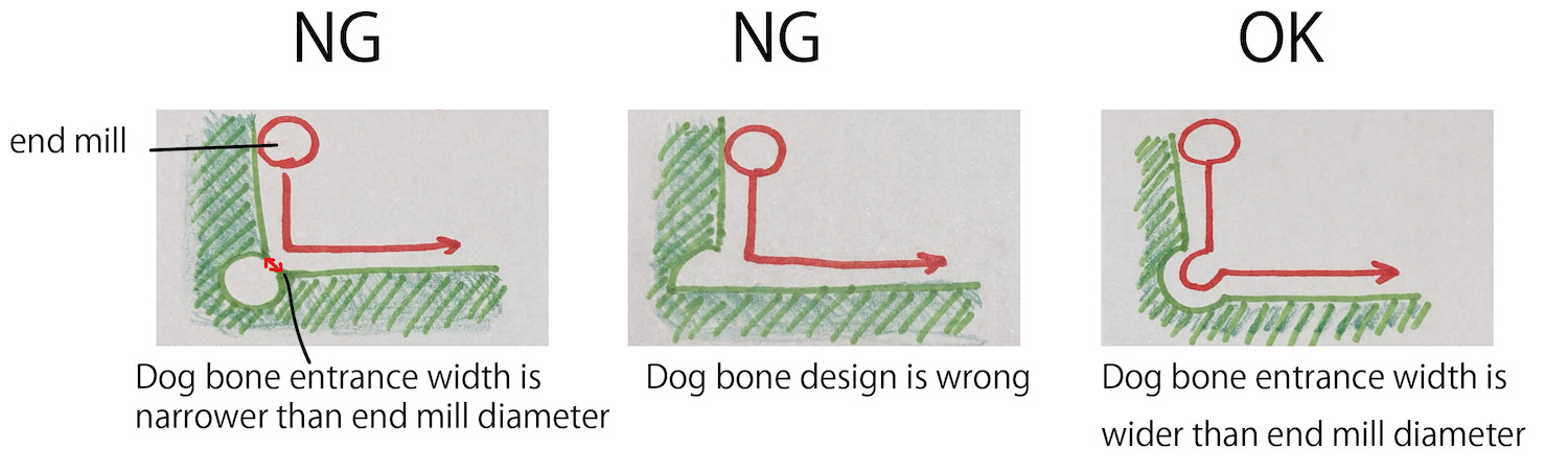
On 11-June. I learned Dogbone addin for fusion 360 from Instructor Ivan. I think this add-in will eliminate mistakes. Thanks a lot.
4-6) Simulate
Action > Simulate
- check the tool path and time.
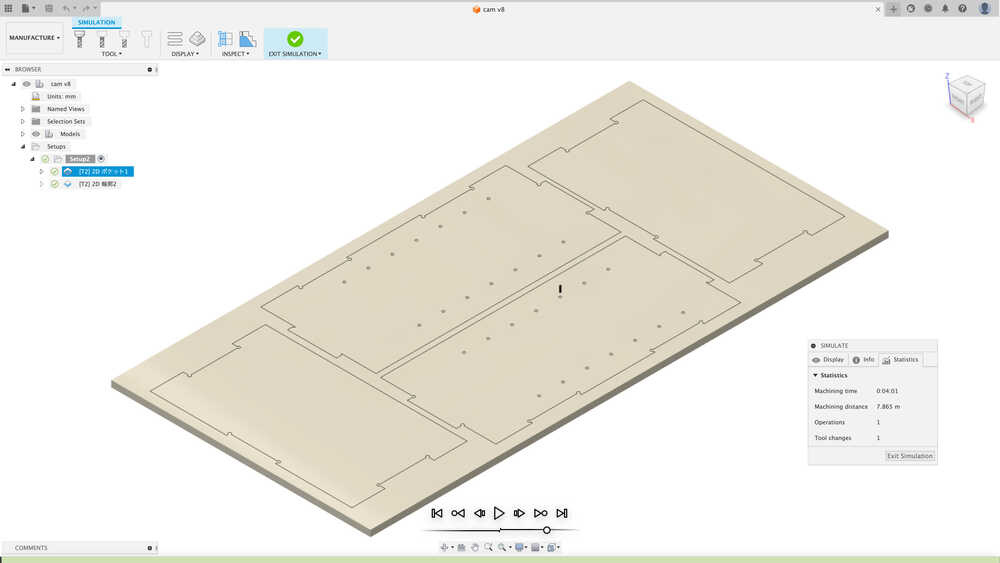
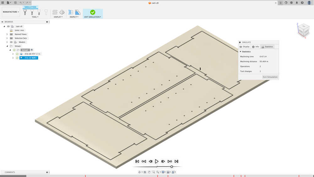
- NOTE:In fact, it took about three times as long as the simulation time. (The Fusion360 simulation was based on cutting everything at top speed.)
4-7) Post Process
Action > Post Process
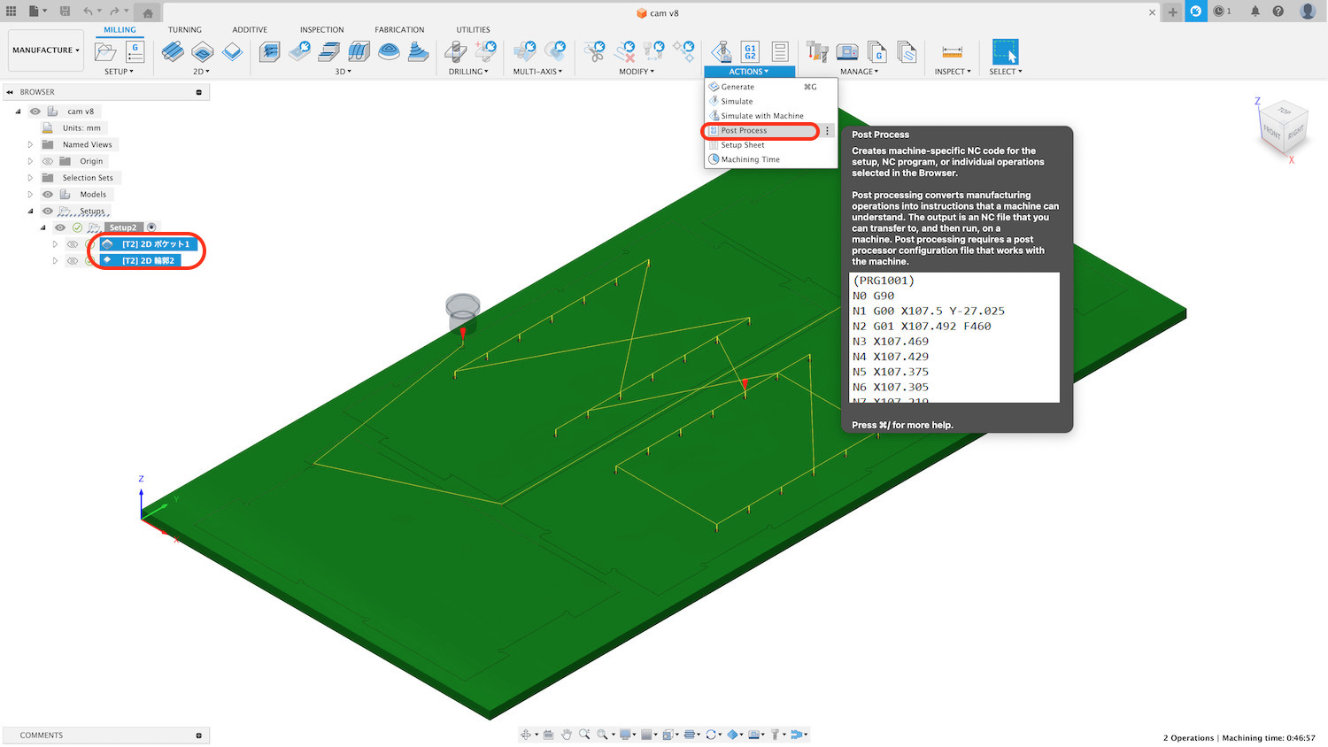
Choose the tool pass you want to post
- Post : Mach4Mill/mach4mill
- Program name
- output folder: Select folder
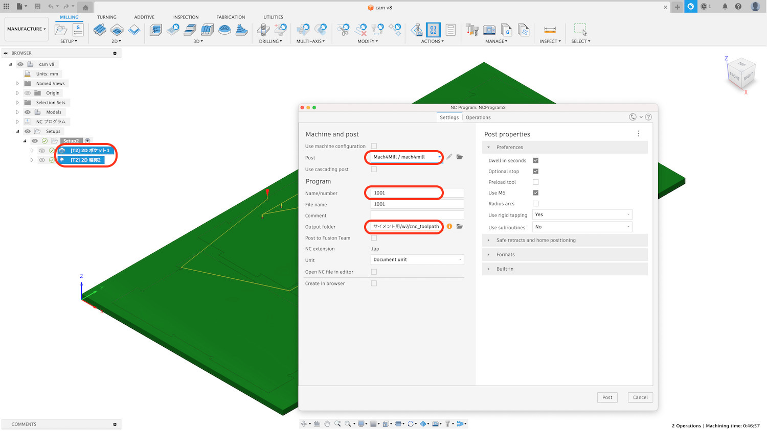
Then success message appeared
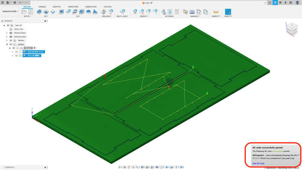
Then out put tool path with ".tap file".
Then, it's time to machine operation.