- STEP RESPONSE
This page is my work process for week 11 Input device, STEP RESPONSE. I refer to Adrian's Fab-Xiao - Step response and Robert Hart's tutorial.
1. About Step response
The step-response is a sensor that is made with two sheets of copper, separated from each other by a porous insulating material. It can be used to calculate the value of force, weight, resistance.
A series of pulses is sent through the TX electrode, which, depending on the material between the two electrodes, allows more or less that series of pulses to pass. In the following graph you can see how it works. The other electrode will be connected between two resistors, one for pull-up and the other for pull-down and to an analog input.
2, Connection
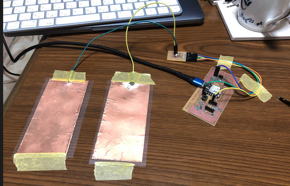
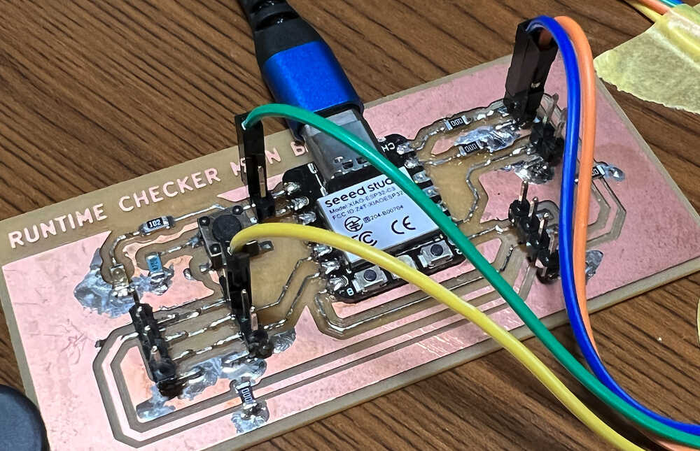
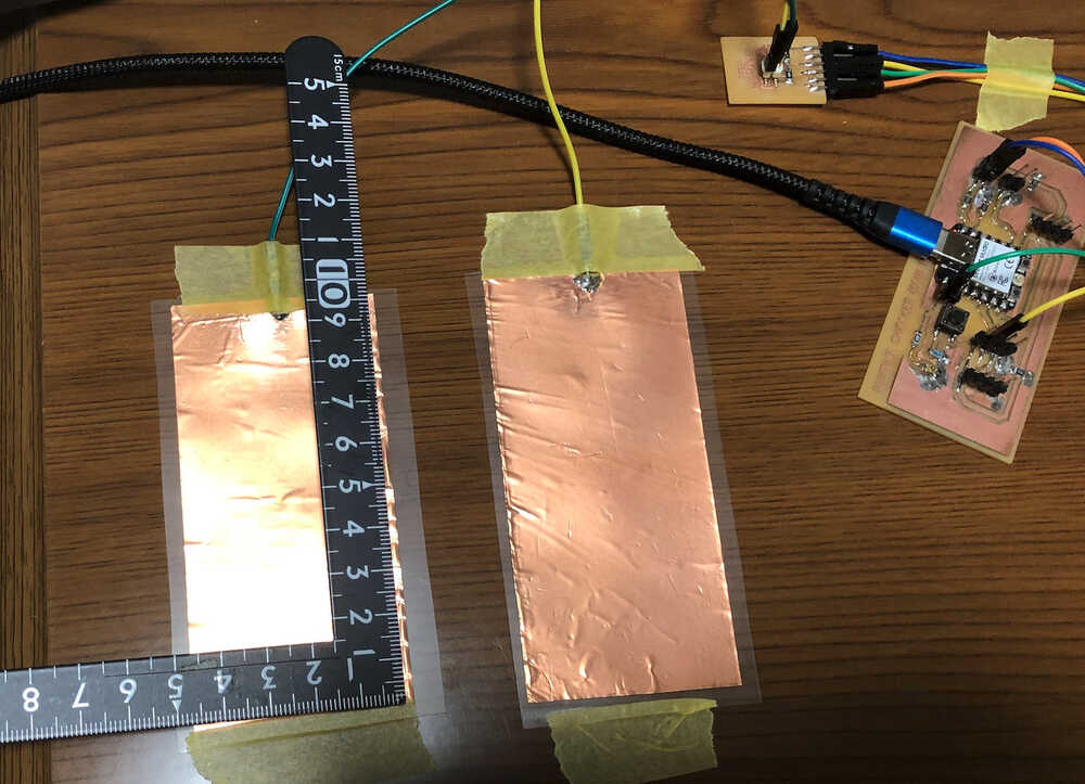
I create my own component by Copper Foil Tape. Then I added analog pin to the board in Week09 before modificated. And I made Adrian's step response board. I use the analog input from the Seeed XIAO ESP32C3 GPIO 2 for the RX and a digital output from the Seeed XIAO ESP32C3 GPIO 6. The connection is as follows.
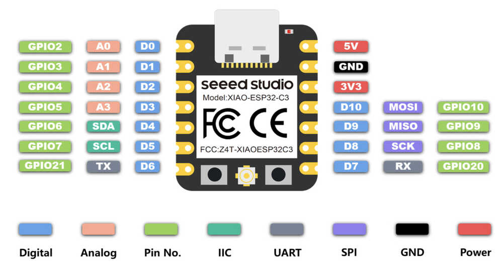
3. Pinout Seeed XIAO ESP32C3
4. Programming
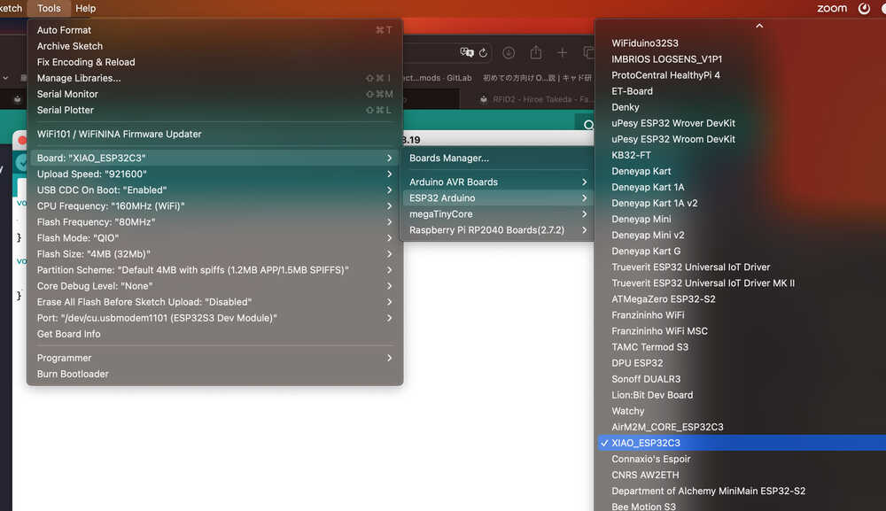
I open Arduino IDE and choose board "XIAO_ESP32C3".
4-1) Programming code, Arduino IDE
I use the reference code for Arduino IDE. "tx_rx03 Robert Hart Mar 2019." and modified by Adrian Torres.
//tx_rx03  Robert Hart Mar 2019.
//https://roberthart56.github.io/SCFAB/SC_lab/Sensors/tx_rx_sensors/index.html

//Modified by Adrián Torres Omaña
//Fab Academy 2023 - Fab Lab León
//Step Response TX, RX
//Fab-Xiao

//  Program to use transmit-receive across space between two conductors.
//  One conductor attached to digital pin, another to analog pin.
//
//  This program has a function "tx_rx() which returns the value in a long integer.
//
//  Optionally, two resistors (1 MOhm or greater) can be placed between 5V and GND, with
//  the signal connected between them so that the steady-state voltage is 2.5 Volts.
//
//  Signal varies with electric field coupling between conductors, and can
//  be used to measure many things related to position, overlap, and intervening material
//  between the two conductors.
//


long result;   //variable for the result of the tx_rx measurement.
int analog_pin = 2; //  GPIO 2 of the XIA0 ESP32C3
int tx_pin = 6;  //     GPIO 6 of the XIA0 ESP32C3
void setup() {
pinMode(tx_pin,OUTPUT);      //Pin 2 provides the voltage step
Serial.begin(115200);
}


long tx_rx(){         //Function to execute rx_tx algorithm and return a value
                      //that depends on coupling of two electrodes.
                      //Value returned is a long integer.
  int read_high;
  int read_low;
  int diff;
  long int sum;
  int N_samples = 100;    //Number of samples to take.  Larger number slows it down, but reduces scatter.

  sum = 0;

  for (int i = 0; i < N_samples; i++){
   digitalWrite(tx_pin,HIGH);              //Step the voltage high on conductor 1.
   read_high = analogRead(analog_pin);        //Measure response of conductor 2.
   delayMicroseconds(100);            //Delay to reach steady state.
   digitalWrite(tx_pin,LOW);               //Step the voltage to zero on conductor 1.
   read_low = analogRead(analog_pin);         //Measure response of conductor 2.
   diff = read_high - read_low;       //desired answer is the difference between high and low.
 sum += diff;                       //Sums up N_samples of these measurements.
 }
  return sum;
}                         //End of tx_rx function.


void loop() {

result = tx_rx();
result = map(result, 17000, 23000, 0, 64);  //I recommend mapping the values of the two copper plates, it will depend on their size
Serial.println(result);
delay(100);
}
Problem I encountered and how I fixed it.
I put the map function as it is in the reference code, it does not seem to be suitable with values that exceed the Processing map. Therefore, in the code for the Arduino IDE, I changed the value of the map function to "result = map(result, 17000, 23000, 0, 64)".
My copper foil size
4-2) Programming code, Processing
I use the reference code for Processing. Just I change myPort.
//Fab Academy 2021 - Fab Lab León
//Step Response
//Adrianino
//ATtiny1614

import processing.serial.*;

float sensorValue; //variable for the serial data
Serial myPort;

void setup() {  //as dynamic/setup function called initially, only once
  size(1024, 200);// is the window (1024=sensor max. value)
  //replace the port String with the port where your Arduino is connected
  //myPort = new Serial(this, "/dev/tty.wchusbserial1450", 115200);
  myPort = new Serial(this, "/dev/cu.usbmodem1101", 115200); // serial port
  background(255);  //set background white

}

void draw() {  //draw function loops

  noStroke(); // outline
  fill(255,0,0,20); // color inside
  rect(0, 0, sensorValue, height); //position and size

  fill(255,70);
  rect(sensorValue, 0, width-sensorValue, height);

  println(sensorValue);
  fill(0,0,0);// these are the colors inside
  text(sensorValue + " " , sensorValue, height/2);
  textSize(32);

}

void serialEvent(Serial myPort) { // sketch read the serial data
  String inString = myPort.readStringUntil('\n');
  if (inString != null) {
    inString = trim(inString);
    float[] values = float(split(inString, ","));
    if (values.length >=1) {
      sensorValue = values[0]; //first value in the list
    }
  }
}
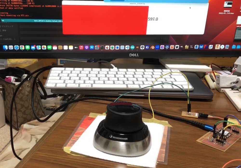
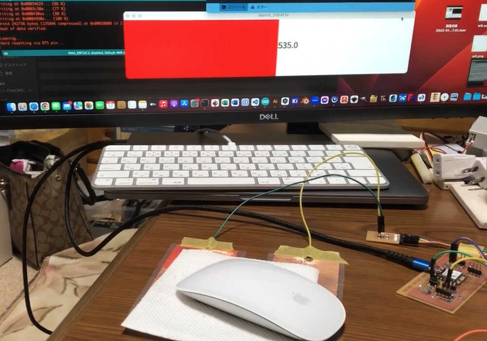
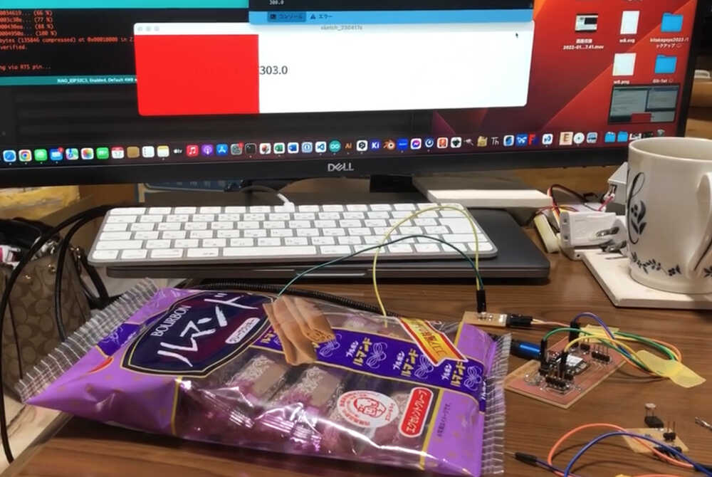
5. VIDEO (The Result)
- As a extra, I test that I placed objects on top of cooper foil.
- 3d mouse
- Magic mouse
- Rumande (Sweet: coffee liqueur flavored with caramel, cream or yolk)
- 3d mouse
6. My Thought
- The Step response is interesting sensor
- It was fun to make module by hand.
- I thought it would be easy to measure, but it was not easy until I changed the value of the map function.