- Original development board
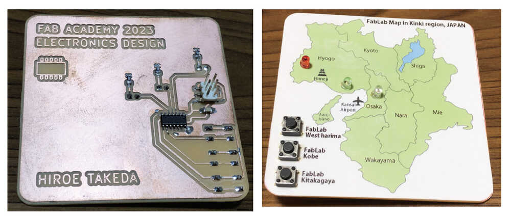
I designed my original development board with ATtiny414, with LED and Pushbutton switch.
For the test, I made and used Bridge Serial FT230XS and Serial to UPDI in "Programmers Summary of FabAcademy".
Start create the board. The process is below.
1. ATtiny414 Board, LED & switchehes
I had made the original board in pre-study, but I had used through-hole components for the LEDs and pushbutton switches. I was advised in open time to recreate it with SMD components, so I decided to rebuild them.
The process is as follows.
At first, I edit Schematic, using Kicad. (The usage of Kicad is the same as that described in Week 06, so it will be omitted.)
1-1) Schematic
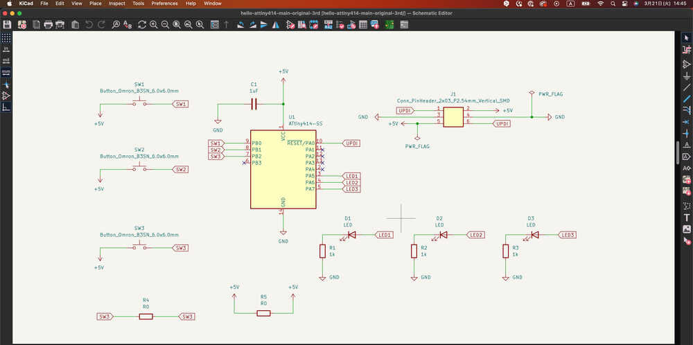
- The Footprint
- change SMD LED and SMD Button.
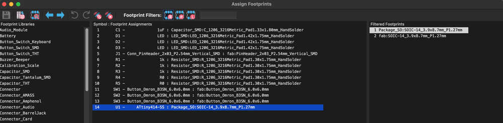
- change SMD LED and SMD Button.
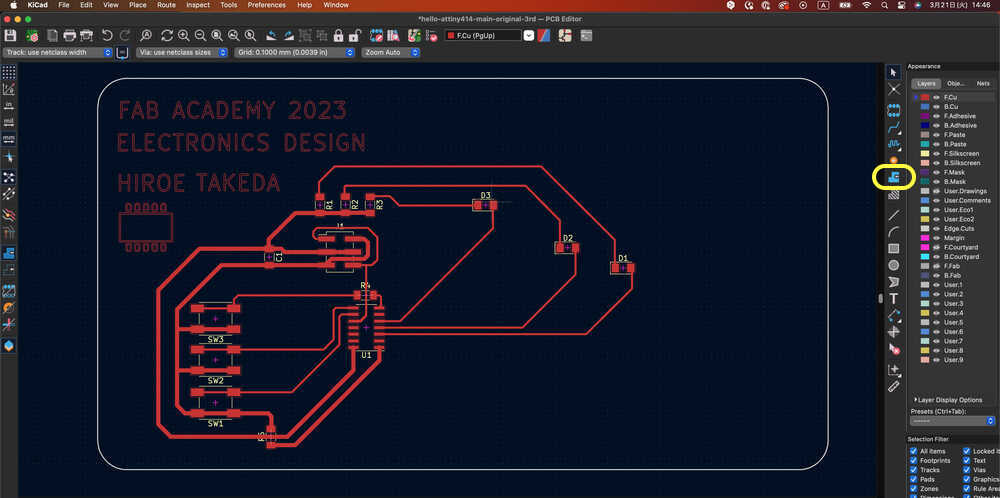
1-2) Board design
I made board design below, then did "Ground Plane (Filled Zone)".
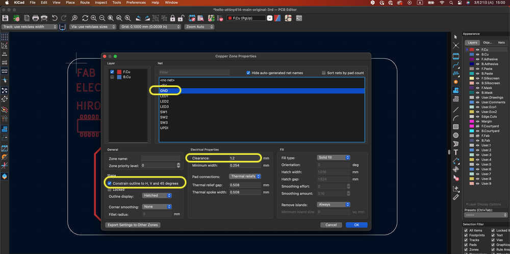
Right click below menu and choose "Fill all zone".
- In Copper Zone Properties
- Layder F.Cu
- Net: GND
- Shape: check for "Constrain outline to H, V and 45 degrees"
- Electrical Propertiews: Clearance: 1.2
- others: default
- Select area, and click "Fill all zone"
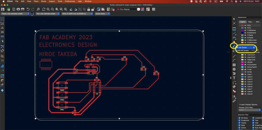
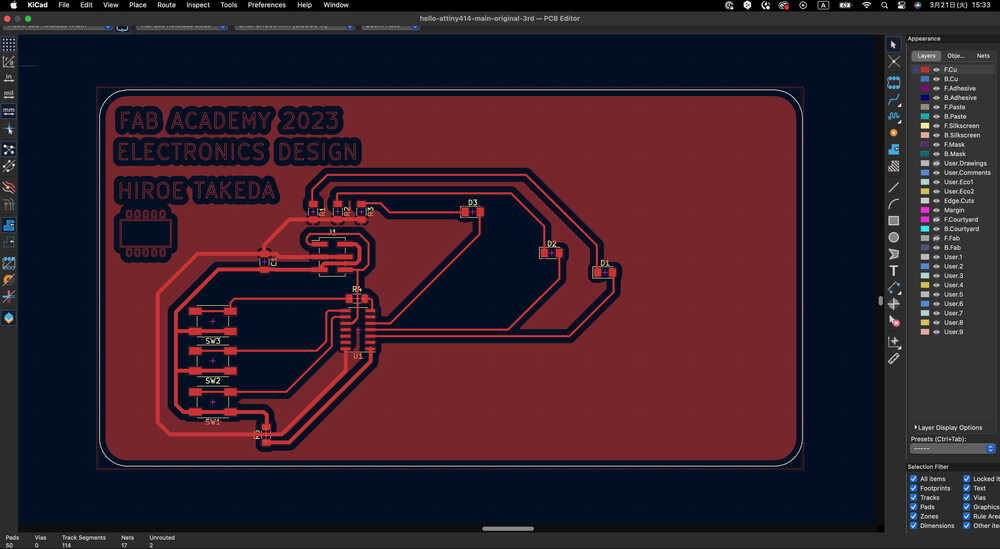
- Ground Plane (Filled Zone) is done.
Useful link:
- KiCAD Ground Plane (Filled Zone)
- KiCad 6: Ground Plane (Filled Zone)
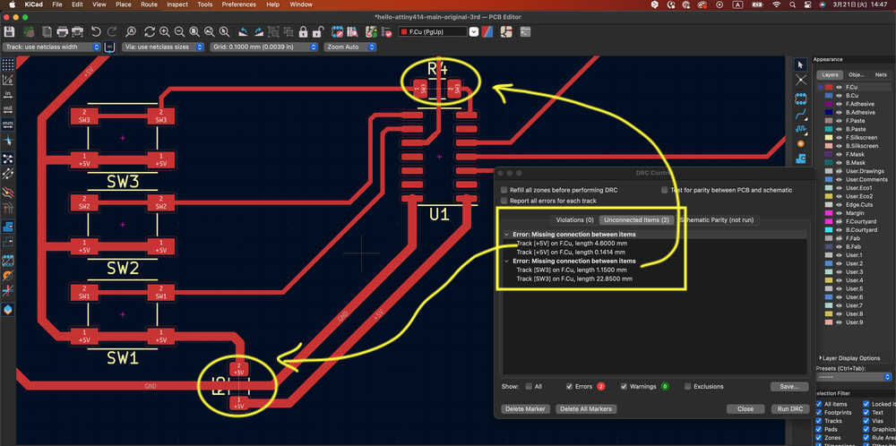
DRC check:
- With DRC check, Below 2 errors unconnecting was appeared, but Registor 0 which I just want to jumb the wire. Therefore DRC check is done!
1-3) BOM
| parts | Amount |
|---|---|
| FR1 | 1 |
| ATtiny414 | 1 |
| LED SMD | 3 |
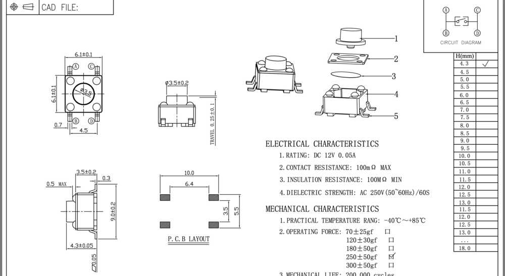
| pushbutton switch, SMD TS-06104 | 3 |
| Capacitor 1μF | 1 |
| Resistor 1kΩ | 3 |
| Resistor 0Ω | 2 |
| Pin header 2x03 P2.54 Vertical SMD | 1 |
Let's move to create Tool path.
1-4) Tool path (V Carve Pro)
- Create path with Vcarve pro.
- About more details -> V Carve Pro
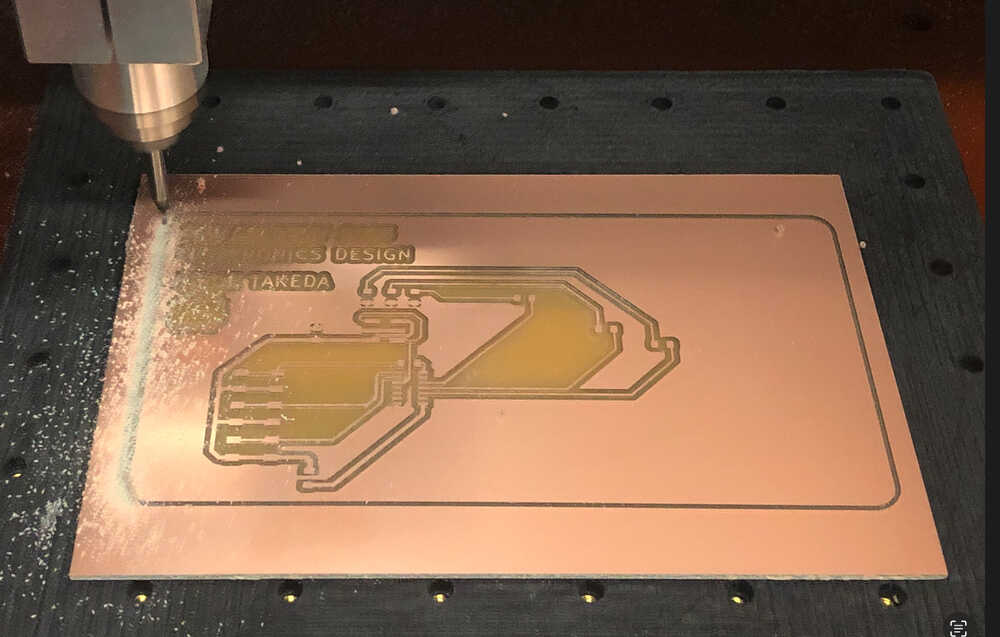
1-5) Milling
- Mill the board with Roland MDX-40A using VPanel software.
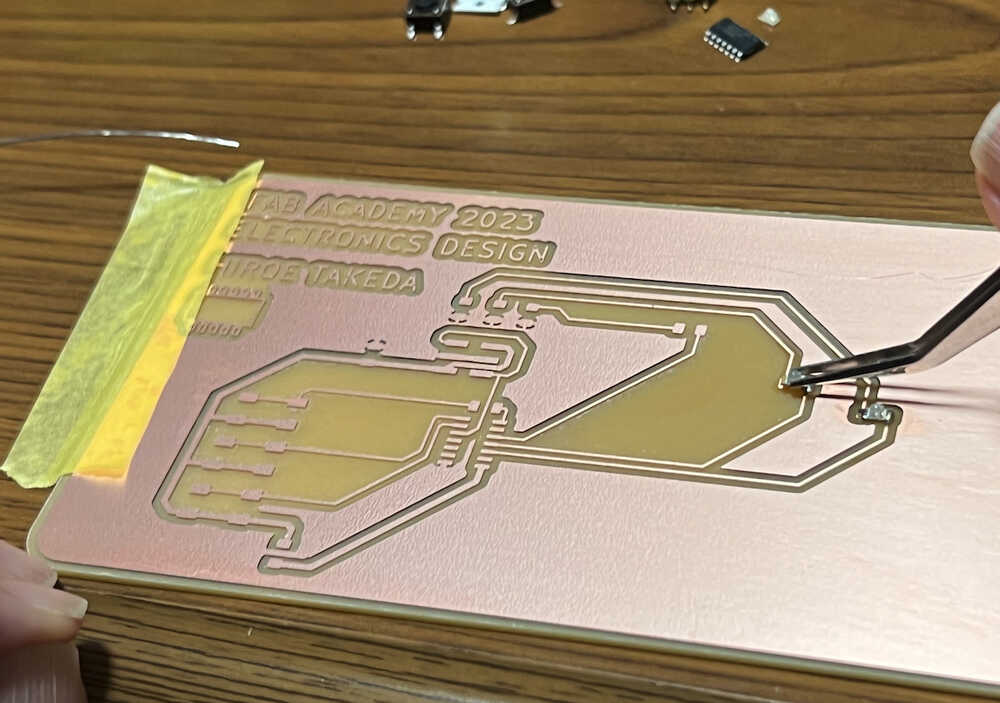
Milling Trace and cut Outline. (The photo is during cut outline.)
 - Done!
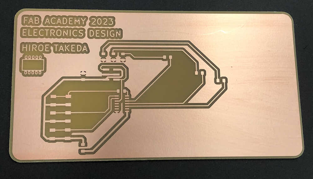
about more details -> MDX-40A, using V Panel
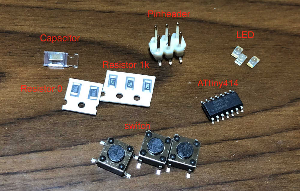
1-6) Soldering
- Prepare electrical parts
- Datasheet check
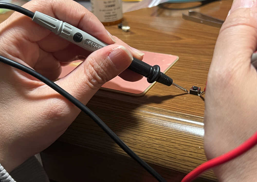
- Before Soldering, check the datasheet for components that need attention.
About Button, I did tester check with Parallel and diagonal (button ON/OFF).
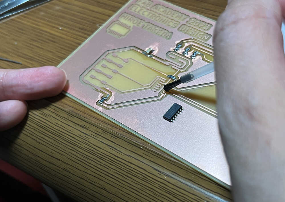
- Solder
- Need to consider before solder, which part is first to solder with image training.
- Small parts -> Large parts
- Inside -> Outside
- Start Soldering. Pay attention of LED anodes and cathodes with Board design.
- Using flux, it become easier to solder.
- Solder Button. Pay attention of datasheet and Board design.
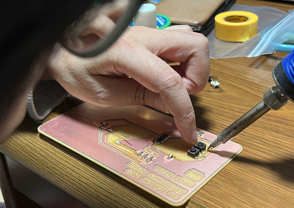
- Solder ATtiny414. As the feet are closely spaced and thin, try to solder them neatly to avoid shorting them out.
1-7) Data file
1-8) Add NOTE on 4-June
- Later I learned that It is not good idea to use buttons connecting them directly to VCC. You should use pull-up or pull-down resistor. Otherwise, when button is not pressed undesired voltage might be induced in the microcontroller detecting wrong values.
My original board is made, but for the test, I need to make Bridge Serial FT230XS and Serial to UPDI in "Programmers Summary of FabAcademy".
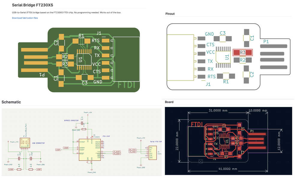
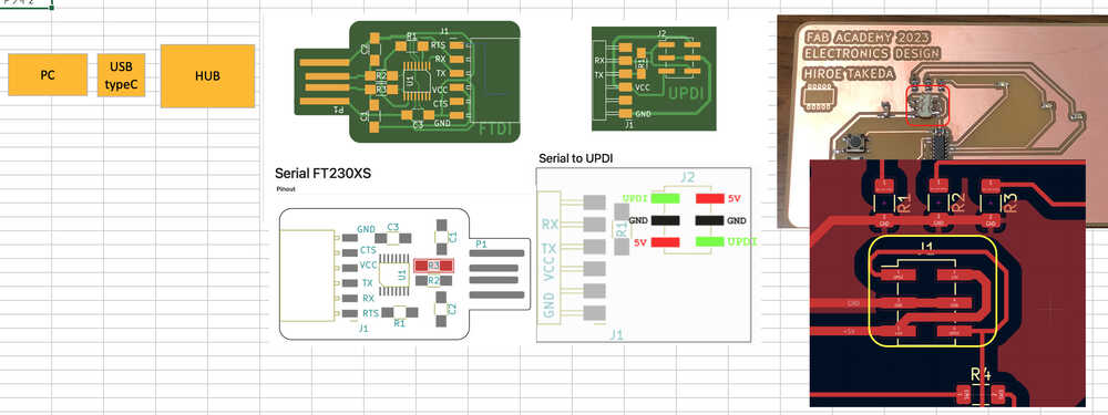
2. Bridge Serial FT230XS
During Pre-study, I made this board.
Process to made
- Get the PCB design (PNG file) from "Bridge Serial FT230XS" in Programmers Summary of FabAcademy.
- Open Illustrator or Inkscape, and rendering PNG file at 1000 DPI.
- Delete unnecessary path (like below) in the image, and export by dxf.
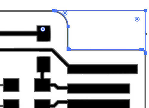
- Trace the image(Black and white logo).
- Change Fill(NONE) and Line(Black, width 0.25).
- Delete unnecessary path
- Export by dxf
- Create tool Path
- Milling
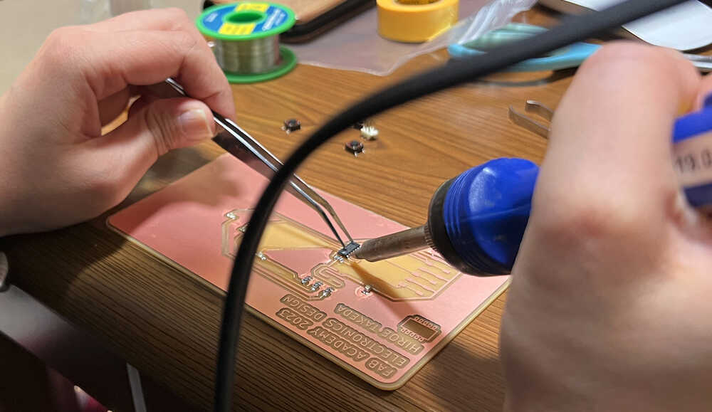
- Soldering
- Tester check
- Done!
Bridge Serial FT230XS" in Programmers Summary of FabAcademy
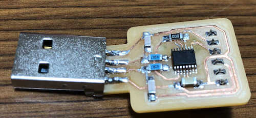
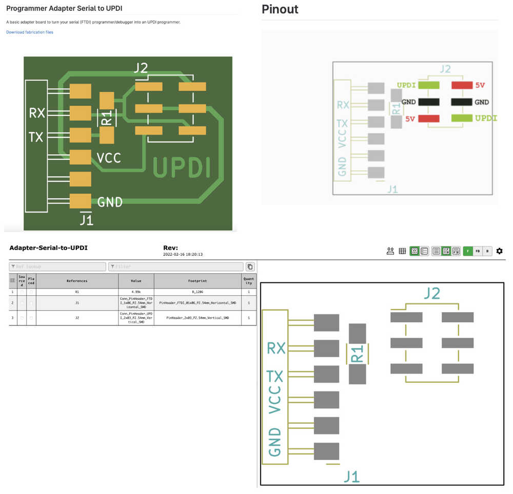
3. Serial to UPDI
- During Pre-study, I made this board. At that time, I was not used to solder, so the solder flowed and was very dirty.
- The creation procedure is the same as above. Difference is which board data to get in Programmers Summary of FabAcademy.
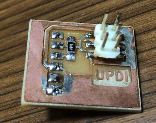
Serial to UPDI in Programmers Summary of FabAcademy
4. Programming with Arduino IDE
Programming to ATtiny412 using Arduino IDE, requires a core for the MegaTinyCore. So I start install it.
4-1) Install "MegaTinycore"
- Open Arduino IDE > setting > preferences
Add the following URL to the "Additional Boards Manager URLs"
http://drazzy.com/package_drazzy.com_index.json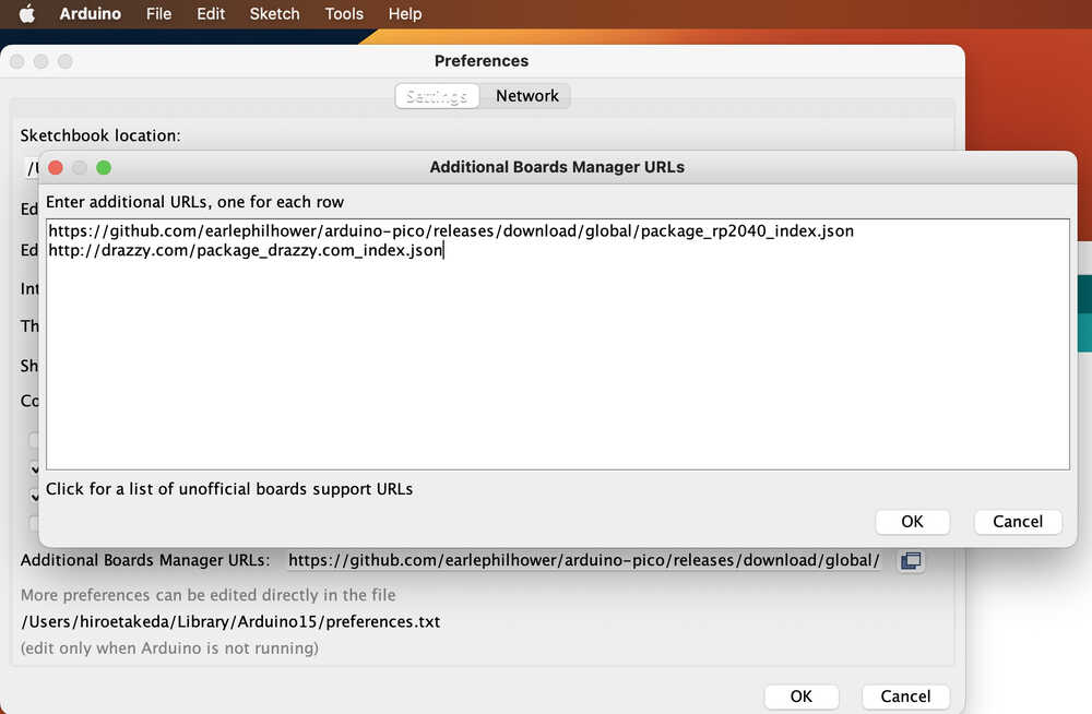
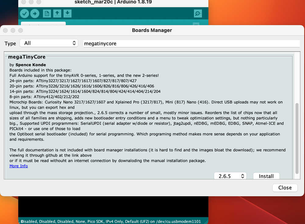
- Go to Tools > Boards > Board Manager
search "megaTinyCore" and install
4-2) Board & Chip
- Choose Board
Tools > Board > choose ATtiny414 is included
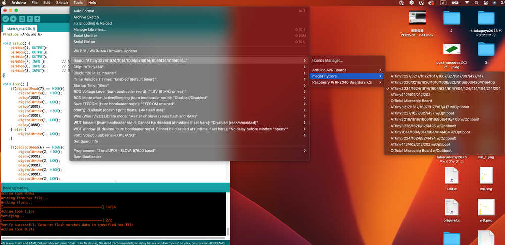
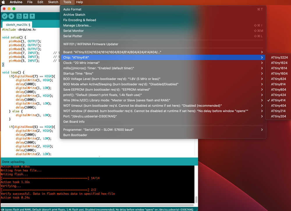
- Choose Chip
Tools > chip ATtiny414
4-3) PC to Board
Check PCB power, GND, and signal locations and make connections to avoid shorts
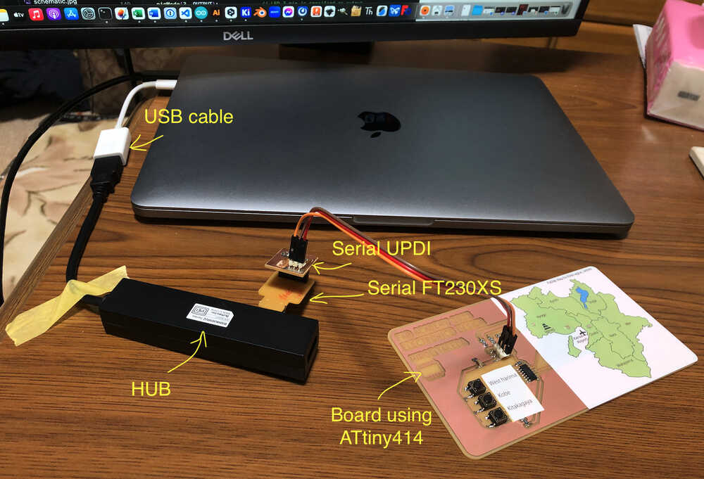
Once connected and the USB port is recognized, go to the next step.
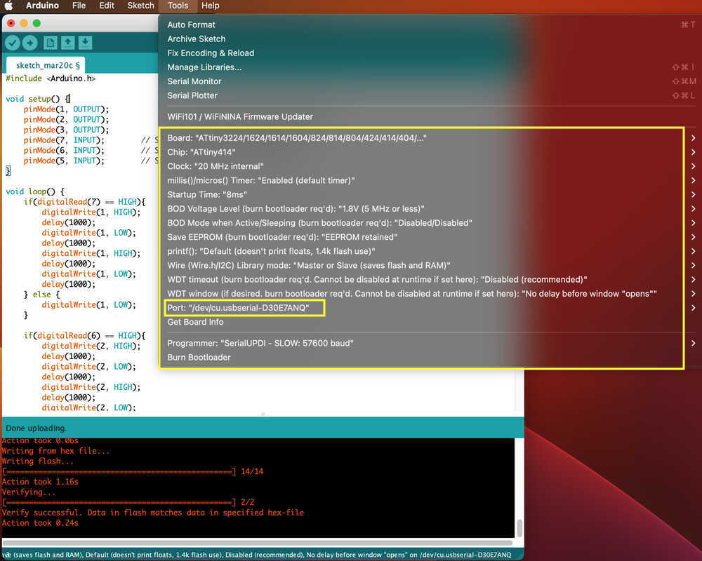
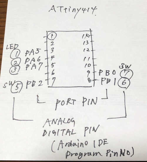
check which Pin on Arduino IDE for my board.
4-4) Programming Code
I made this Programming Code with GPT-4 of ChatGPT.I had to repeat the question many times because I did not put the right keywords in the code that ChatGPT made and the error or LED did not light up.
#include <Arduino.h>

void setup() {
    pinMode(1, OUTPUT);              // LED 1 pin is specified as output
    pinMode(2, OUTPUT);              // LED 2 pin is specified as output
    pinMode(3, OUTPUT);              // LED 3 pin is specified as output
    pinMode(7, INPUT);        // SW 7 pin changed to input_pullup
    pinMode(6, INPUT);        // SW 6 pin changed to input_pullup
    pinMode(5, INPUT);        // SW 5 pin changed to input_pullup
}

void loop() {
    if(digitalRead(7) == HIGH){        // LED 1 turn on, when push SW 7
        digitalWrite(1, HIGH);
        delay(1000);
        digitalWrite(1, LOW);
        delay(1000);
        digitalWrite(1, HIGH);
        delay(1000);
        digitalWrite(1, LOW);
        delay(1000);
    } else {
        digitalWrite(1, LOW);
    }

    if(digitalRead(6) == HIGH){        // LED 2 turn on, when push SW 6
        digitalWrite(2, HIGH);
        delay(1000);
        digitalWrite(2, LOW);
        delay(1000);
        digitalWrite(2, HIGH);
        delay(1000);
        digitalWrite(2, LOW);
        delay(1000);
    } else {
        digitalWrite(2, LOW);
    }

    if(digitalRead(5) == HIGH){        // LED 3 turn on, when push SW 5
        digitalWrite(3, HIGH);
        delay(1000);
        digitalWrite(3, LOW);
        delay(1000);
        digitalWrite(3, HIGH);
        delay(1000);
        digitalWrite(3, LOW);
        delay(1000);
    } else {
        digitalWrite(3, LOW);
    }
}
DATASHEET
- ATtiny414
- Pin out
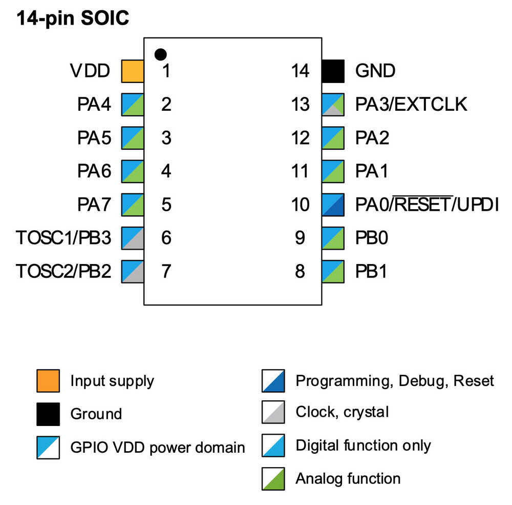
- ATtinyx14 Pinout:
- I was in trouble with Pinout. this MTM: ATTINY Arduino Toolchain help me a lot!
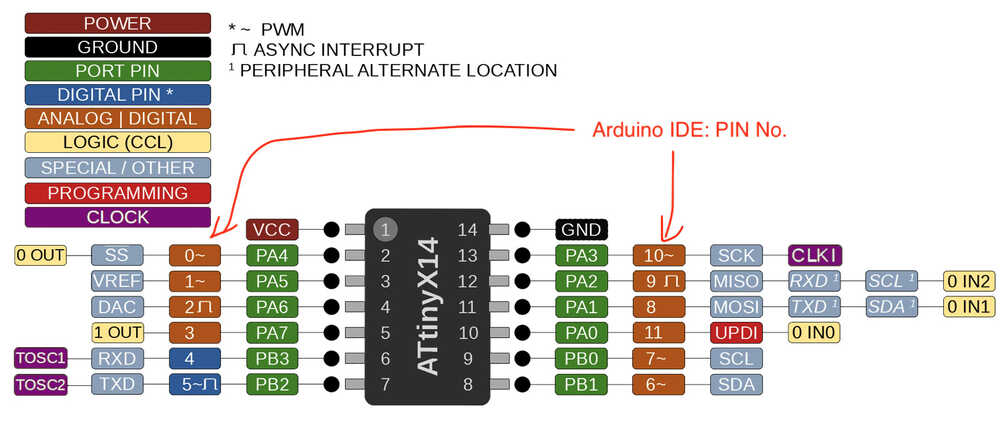
- I was in trouble with Pinout. this MTM: ATTINY Arduino Toolchain help me a lot!
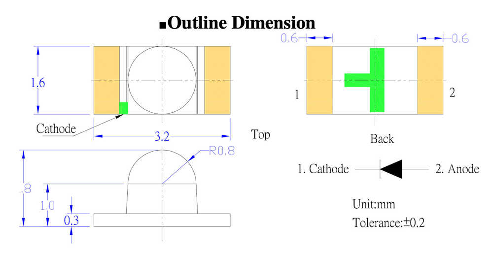
- LED osxx120641e
- Button: SMD TS-06104