Week09. Output Devices
1. Assignment and Result
About the process of Programming, I made new page and made links are below, because the long page makes me confuse.
| GROUP ASSIGNMENT | THE RESULT |
|---|---|
| measure the power consumption of an output device | Process -> Kitakagaya: Week9 Output Devices |
| INDIVIDUAL ASSIGNMENT | THE RESULT |
|---|---|
| add an output device to a microcontroller board you've designed, and program it to do something | Programming microcontroller board with Seeed Studio XIAO ESP32C3 which I designed to turn on the standlight (AC100V) using Solid State Module (SSR-40DA). Process -> Programming process |
2. HERO VIDEO
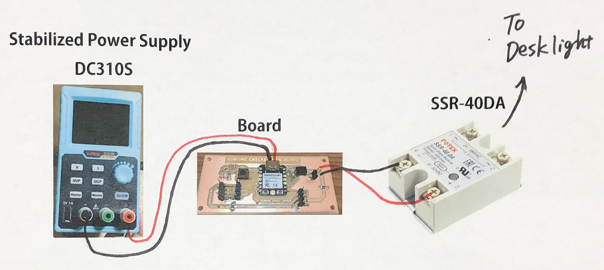
Result, as below Video shows, Programming microcontroller board with Seeed Studio XIAO ESP32C3 which I designed to turn on the Heat Gun (AC100V) using Solid State Module (SSR-40DA). I plan to use SSR-40DA as output device for my final project and machine building, too. So, This result make me happy.
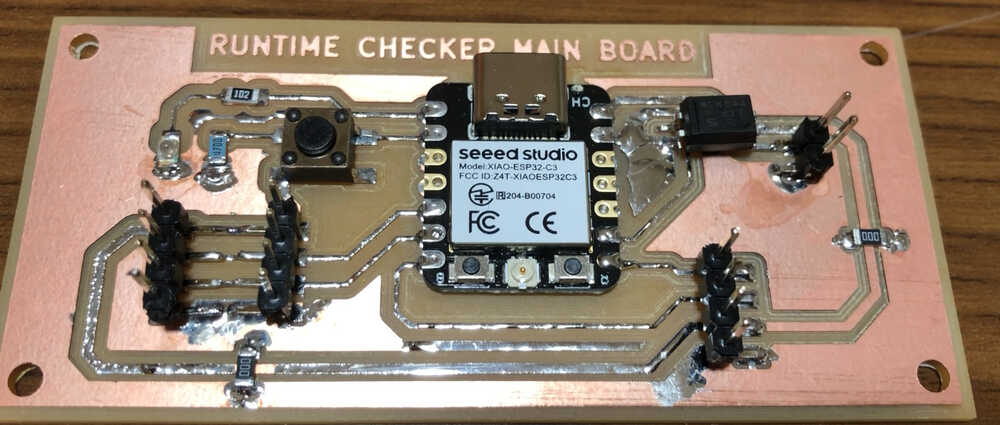
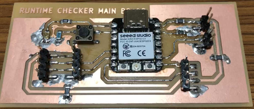
3. HERO SHOT
This is my board (v4) that I designed. This board is prototype of my final project.
4. TEST: Solid State Module (SSR-40DA)
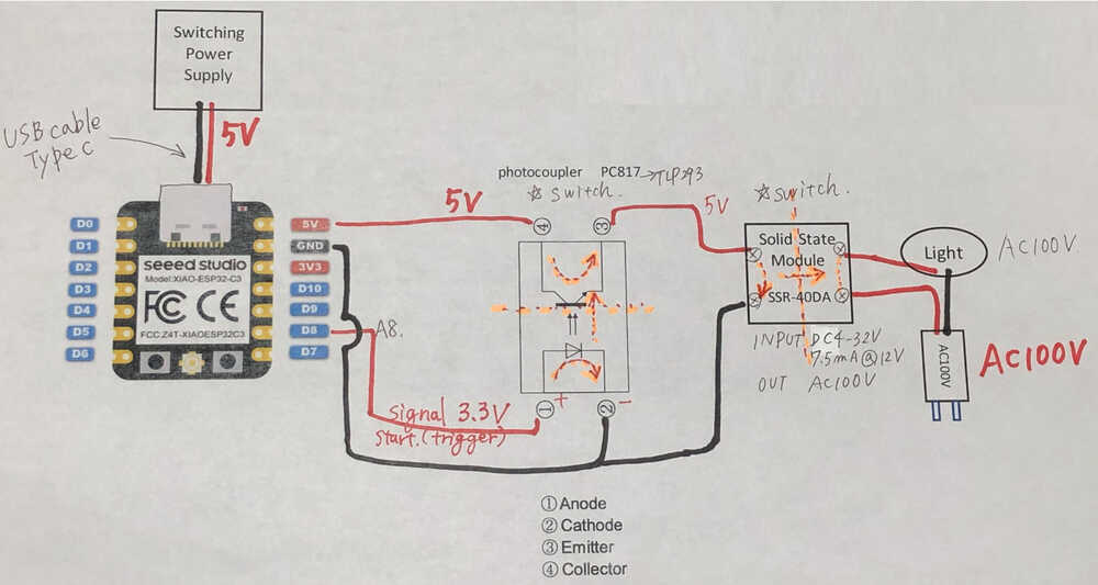
Initially, I planned to connect an external power supply to the 5V pin and the GND pin on the XIAO ESP32C3 board, but since the ESP32C3 board is bi-directionally connected to the USB pin and a short circuit occurs when power voltage is input from both pins, I decided to supply power from the USB pin for safety and use the 5V pin on the XIAO ESP32C3 board as an output power supply for relay operation, not an input.
4-1) TEST1
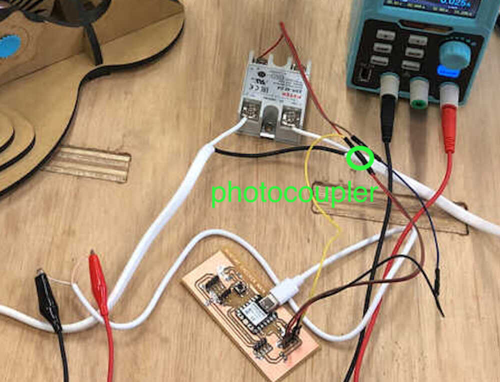
I test programming to turn on light stand (AC100V) using output device "Solid State Module (SSR-40DA)" and microcontroller board with Seeed Studio XIAO ESP32C3, which I designed in Week06, and I add a photocoupler PC817, then light stand turn on with programming. And It works.
Why I add photocoupler?
- Changing the input signal voltage of the Solid State Relay Module (SSR-40DA).
Old version :3-32V
New version :4-32V
(Input control voltage of DC5V or more is recommended for stable operation.)
Datasheet - The input signal voltage of the SSR used was 4-32V and could not be driven by the digital pin voltage (3.3V) of the ESP32C3.
- For the above reasons, I thought of using some kind of device such as a FET or logic level converter to control the 5V voltage with a 3.3V signal voltage.
- For the device to be used, I decided to use a photocoupler that was stocked in large quantities at home.
(I figured I didn't want to pay 1000 yen shipping to buy one FET for 60 yen)
Wire Work
- Since high voltages are handled, it should be taken into account and adequate safety measures (e.g., use appropriate cables...) should be taken.
- After receiving advice from a qualified electrician, the following cables were selected for use with Japanese household power (100V 15A).
- VVF cable (2.0mm^2) Allowable current 23A
- IV cable (2.0mm^2) Permissible current 35A
Soldering v3
 How to connect
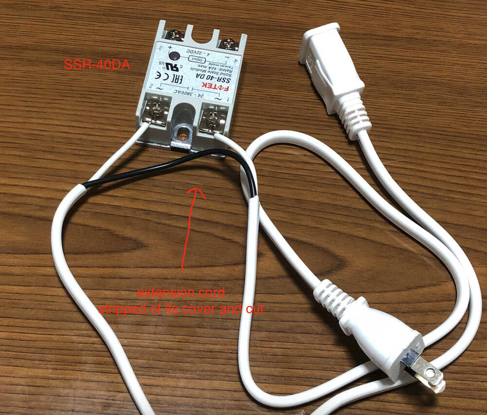
Cable Work1: Solid State Module(SSR-40DA) + extension cord
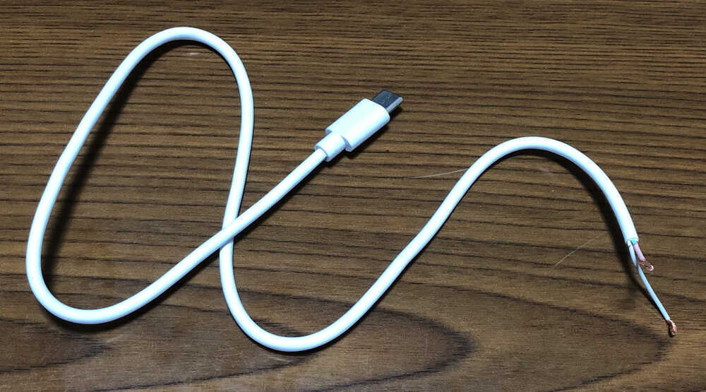
Cable Work2: Cut USB cable TypeC (To connect board and Switching Power Supply.)
Now, photocoupler is not include the board. So, It time to the circuit change add a photocoupler.
4-2)TEST2
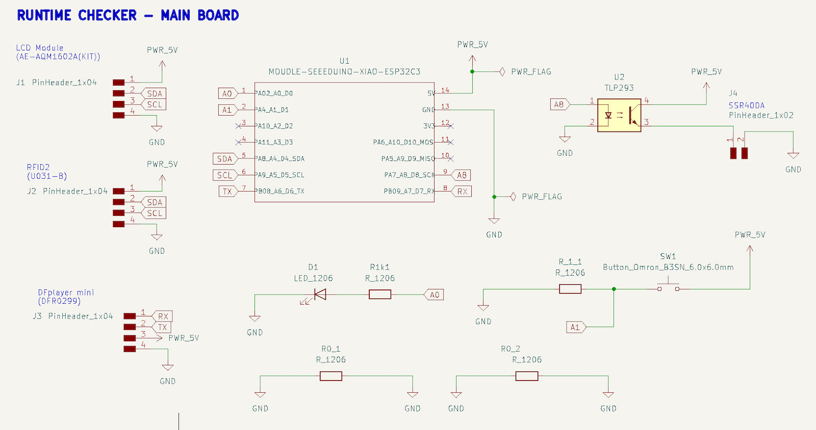
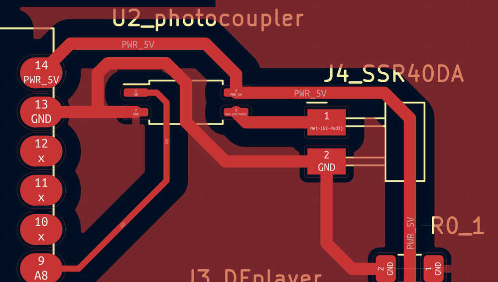
I edit Schematic & Board design as below to make new version board.
Schematic
Board design Whole design
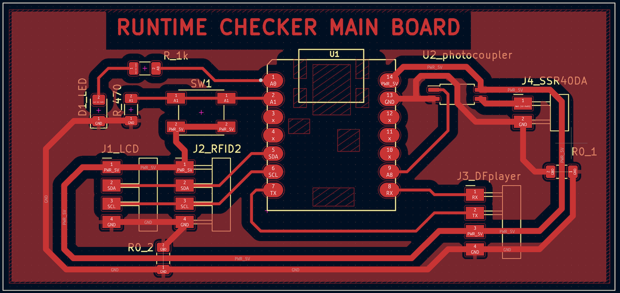
Board design Zoom of a part around photocoupler
Soldering v4. The photo is in Hero shot on this page.
5. measure the power consumption
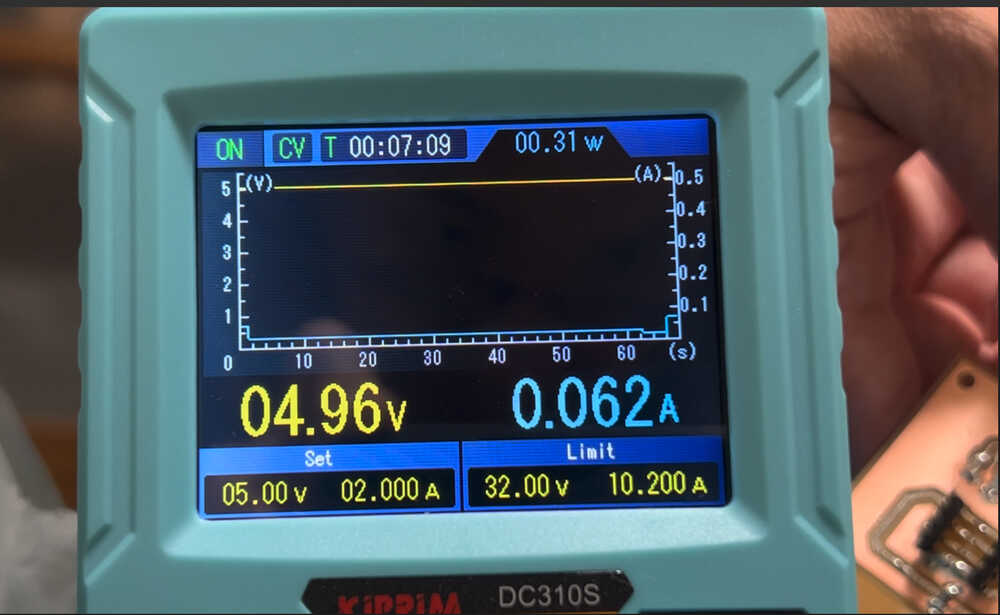
I measure the power consumption and standby power for an Solid State Module (SSR-40DA) and my main board. Measuring Equipment is DC310S.
-
Power consumption of board and SSR (ON)
(NOTE: Power consumption of desk light is not included.)- E = V × I
- 0.31W (0.30752 (E) = 4.96 (v) x 0.062 (A)), in this time
-
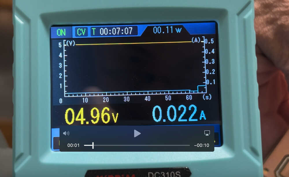
Standby power (Power consumption of board (SSR OFF))
- E = V × I
- 0.11W (0.310912 (E) = 4.96 (v) x 0.022 (A)), in this time
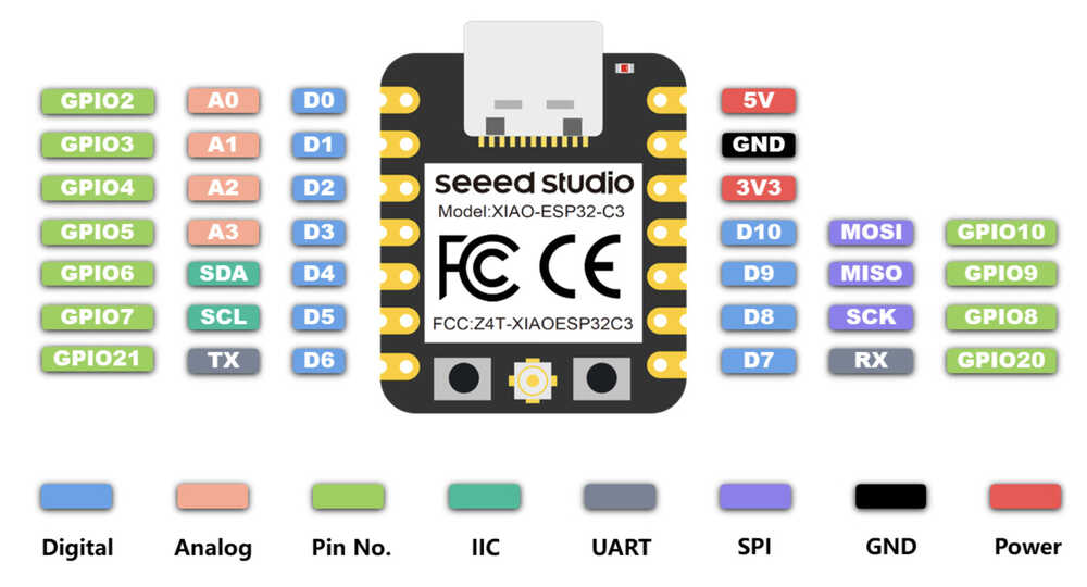
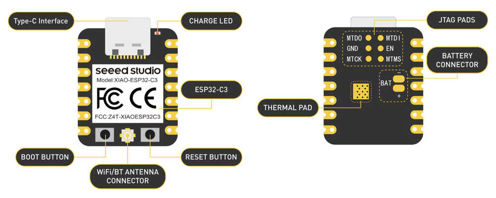
6. Datasheet of XIAO ESP32-C3
Seeed Studio XIAO ESP32C3 is an IoT mini development board based on the Espressif ESP32-C3
- Features
- Powerful CPU: ESP32-C3, 32bit RISC-V singlecore processor that operates at up to 160 MHz
- Complete WiFi subsystem: Complies with IEEE 802.11b/g/n protocol and supports Station mode, SoftAP mode, SoftAP + Station mode, and promiscuous mode
- Bluetooth LE subsystem: Supports features of Bluetooth 5 and Bluetooth mesh
- Ultra-Low Power: Deep sleep power consumption is about 43μA
- Better RF performance: External RF antenna included
- Battery charging chip: Supports lithium battery charge and discharge management
- Rich on-chip resources: 400KB of SRAM, and 4MB of on-board flash memory
- Rich interfaces: 1xI2C, 1xSPI, 1xI2S, 2xUART, 11xGPIO(PWM), 4xADC, 1xJTAG bonding pad interface
7. My Thought
- This is the prototype for my final project board. I am happy with that the relay work with test.
- I often heard that this week is easy, but that was not the case for me at all. Every time I upload programming, I had to pray.
8. Data file
Board design - runtime checker main board v4 (Kicad)