Work log - Week 15 - May 4, 2022
Wednesday 5/4
Links from Class
A lot of them from today. Class was rather overwhelming. It was basically every type of programming software ever invented. But there was good information buried in there.
Like this guys stuff: https://fabacademy.org/2022/labs/kamplintfort/students/jan-bewersdorff/
Neil Metrology thingy: http://cba.mit.edu/events/22.08.OM/
https://www.haystack-mtn.org/haystack-labs
https://github.com/jakeread/clank-mudstack
https://fabacademy.org/2021/labs/plusx/students/john-story/assignments/week14/
https://fabacademy.org/2022/labs/sorbonne/students/chloe-laurent/assignments/week14/#programming
https://github.com/mqtt/mqtt.org/wiki/public_brokers
https://observablehq.com/@d3/gallery
https://gitlab.com/fab-lab-oulu/fabbed_vr_glasses
https://fab.cba.mit.edu/classes/864.20/index.html
https://teachablemachine.withgoogle.com/
https://fabacademy.org/2022/labs/cidi/students/victor-ughelli/assignments/week08/
https://hackaday.com/2022/04/27/cad-sketcher-its-parametric-cad-for-blender/
and FYI: cool notes on inkscape shapes: https://inkscape.org/doc/tutorials/shapes/tutorial-shapes.html
Other notes from today
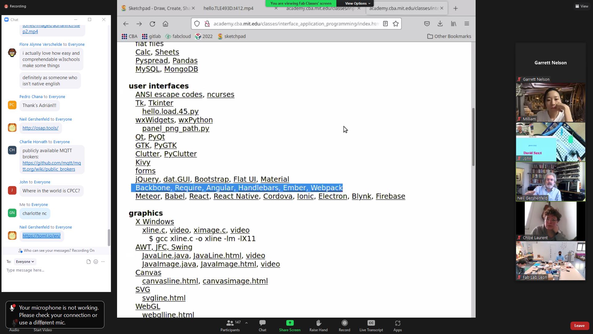
I managed to get CPCC some worldwide attention. WORLDWIDE.
John from Wales (?) https://fabacademy.org/2021/labs/plusx/students/john-story/assignments/week14/ had a cool demonstration where you could send a message to his electronics board over the MQTT demonstration to turn on or off an LED, and it displayed your name on the screen. So I hooked up one of my SAMD11 boards, changed some of the code around to handle Serial over USB, the pin numbers for buttons and leds, etc. and sent a button press.
I sent one with “CPCC” and one with “Charlotte NC”
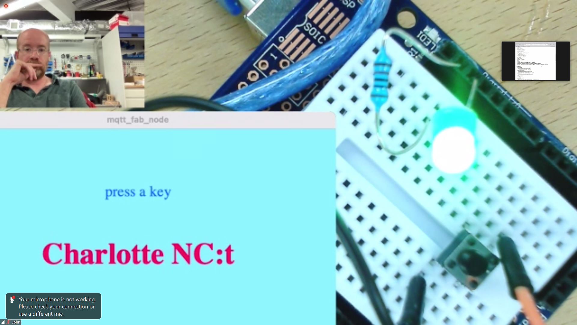
I may have sent a few others as well…
Lots of updating and filling in documentation, cleaning up board files, etc. today.
Thursday 5/5
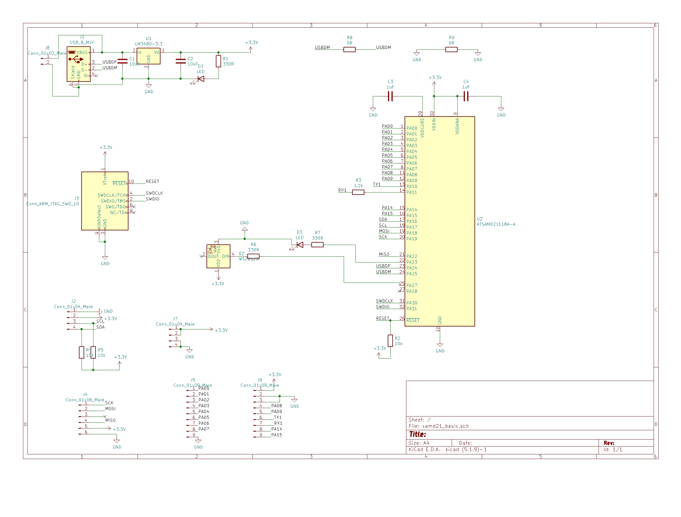
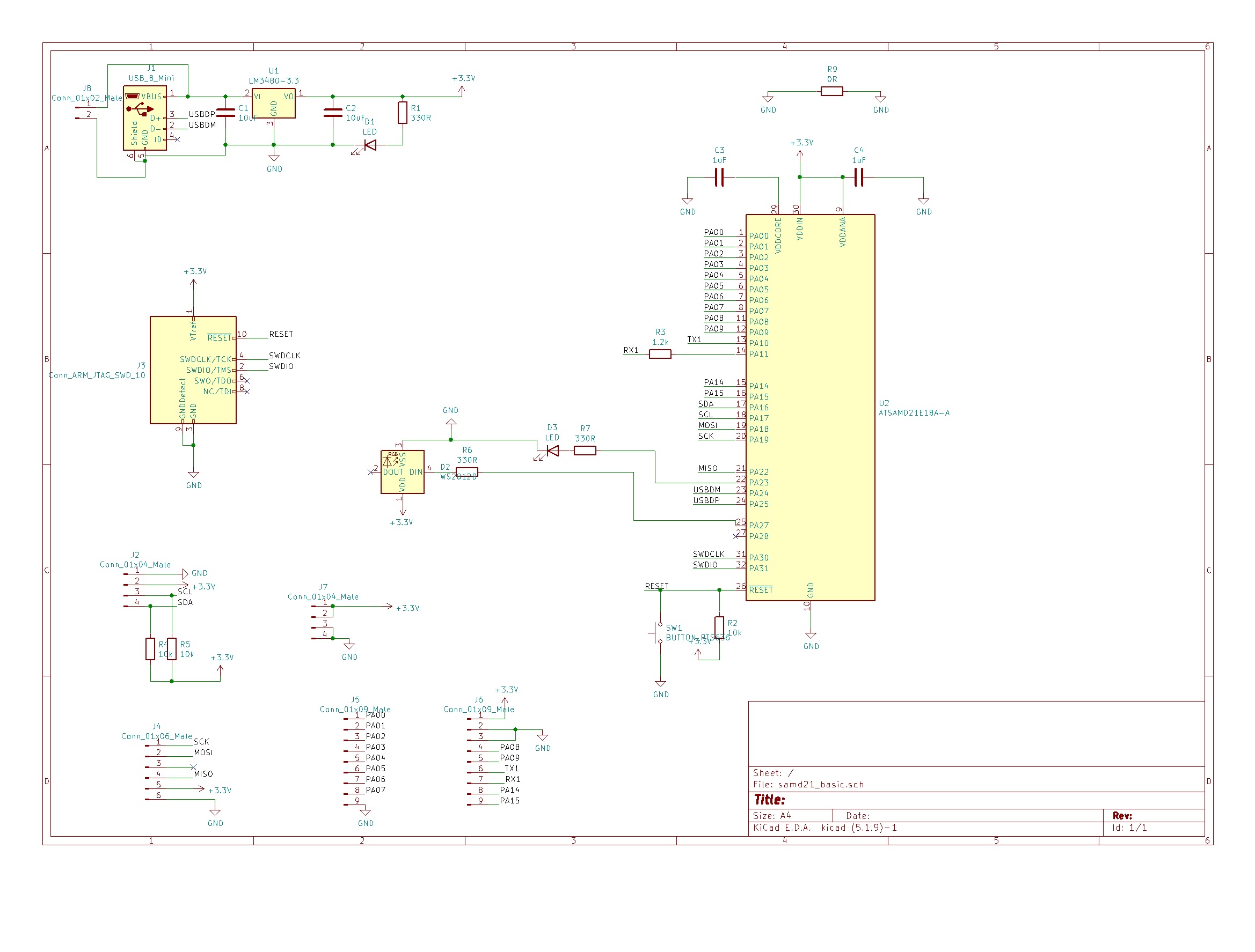
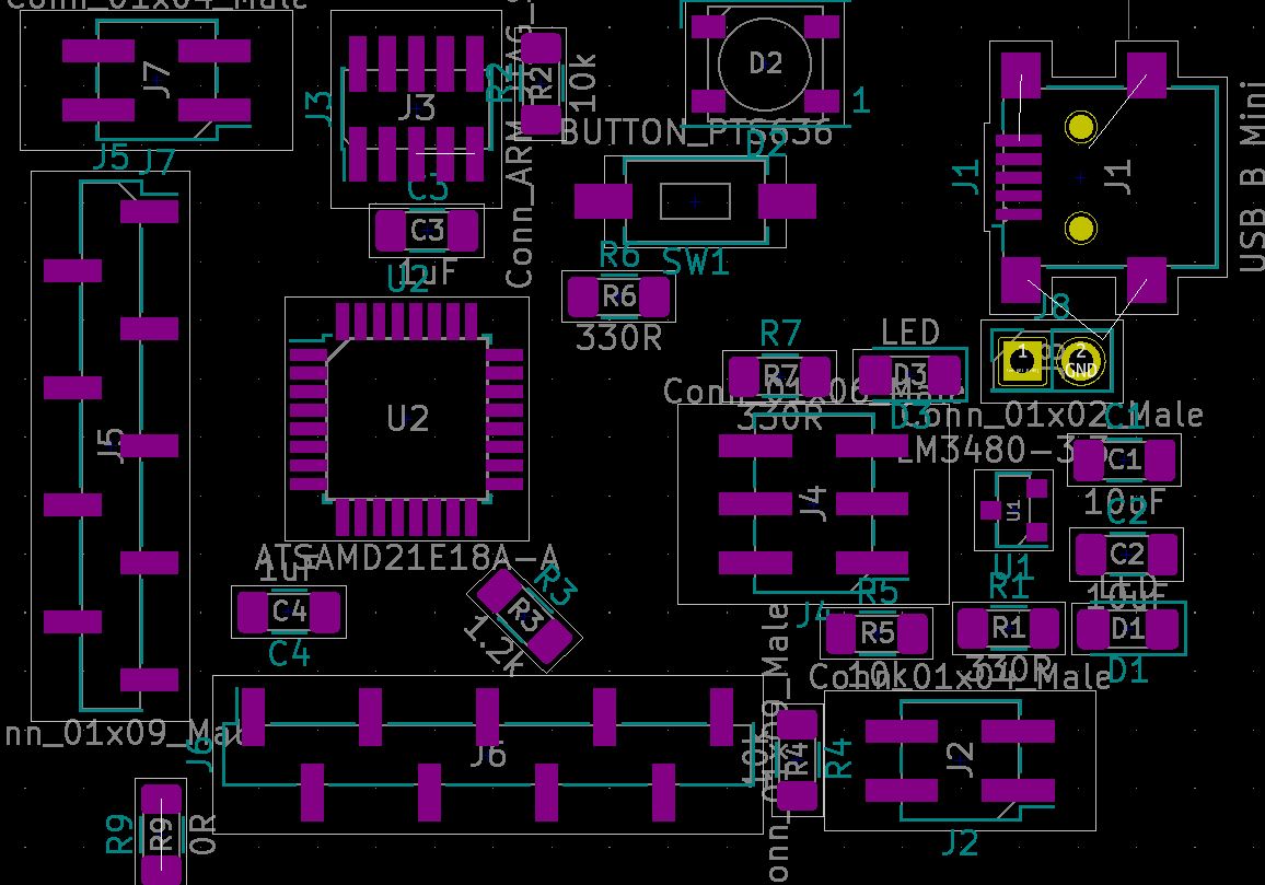
Spent just about all day working on a new SAMD21 board. I didn’t really want too, but I think I’m going to need to have something like this for my final project, because I don’t think I can get what I need from the attiny412 or samd11, mostly for lack of memory. I’d love a microcontroller that was small, but just had a ton of flash to store my programs, and enough ram to run them, that was also easy to use.
Designing this board, I was wondering why chip manufacturers don’t behave sanely, and have some type of standard in the order they put pins, so at the very least you don’t have to cross wires to get the signal from the output to inpu (for instance, something like USB or JTAG.) But then I realized that no sane person makes single sided boards anymore.
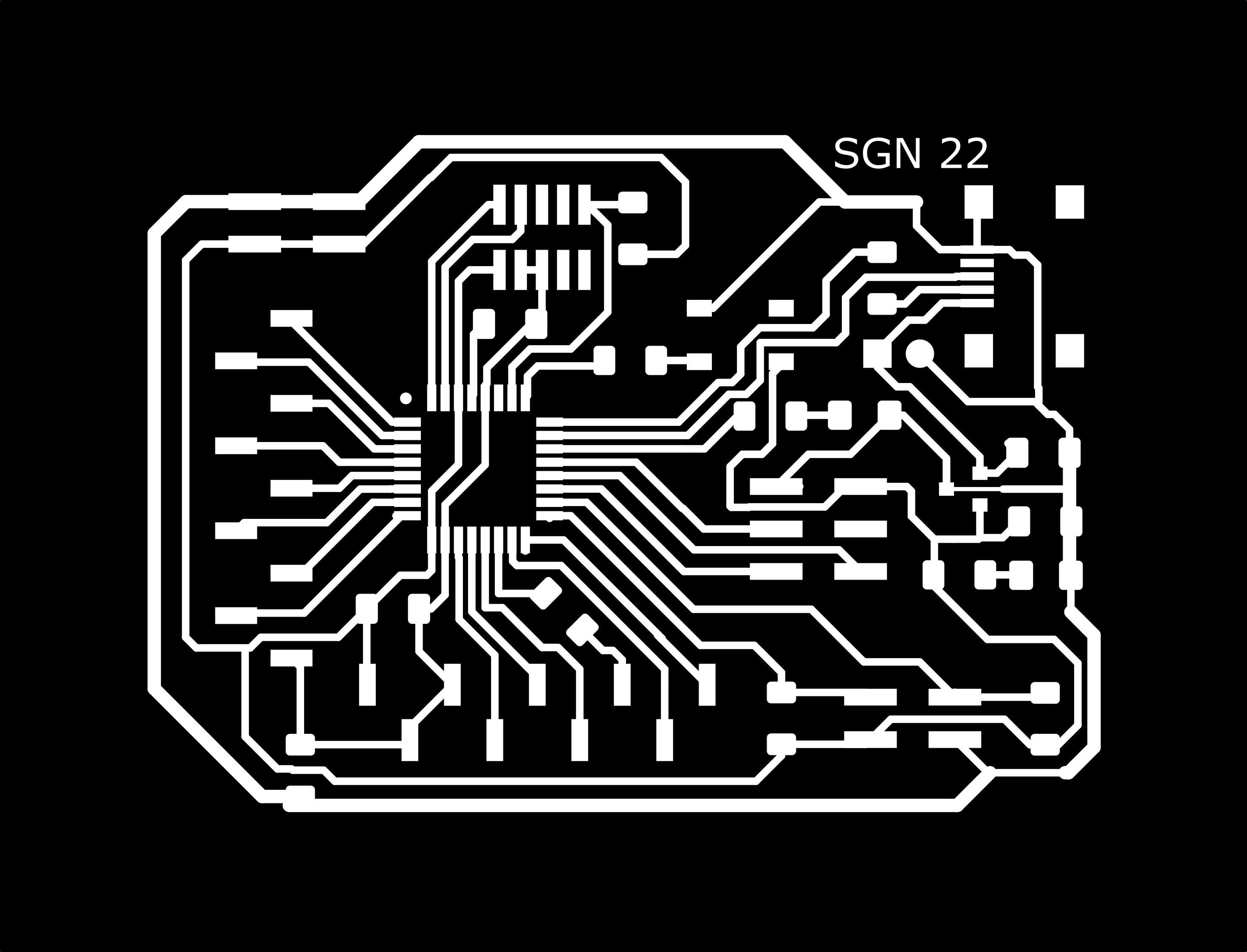
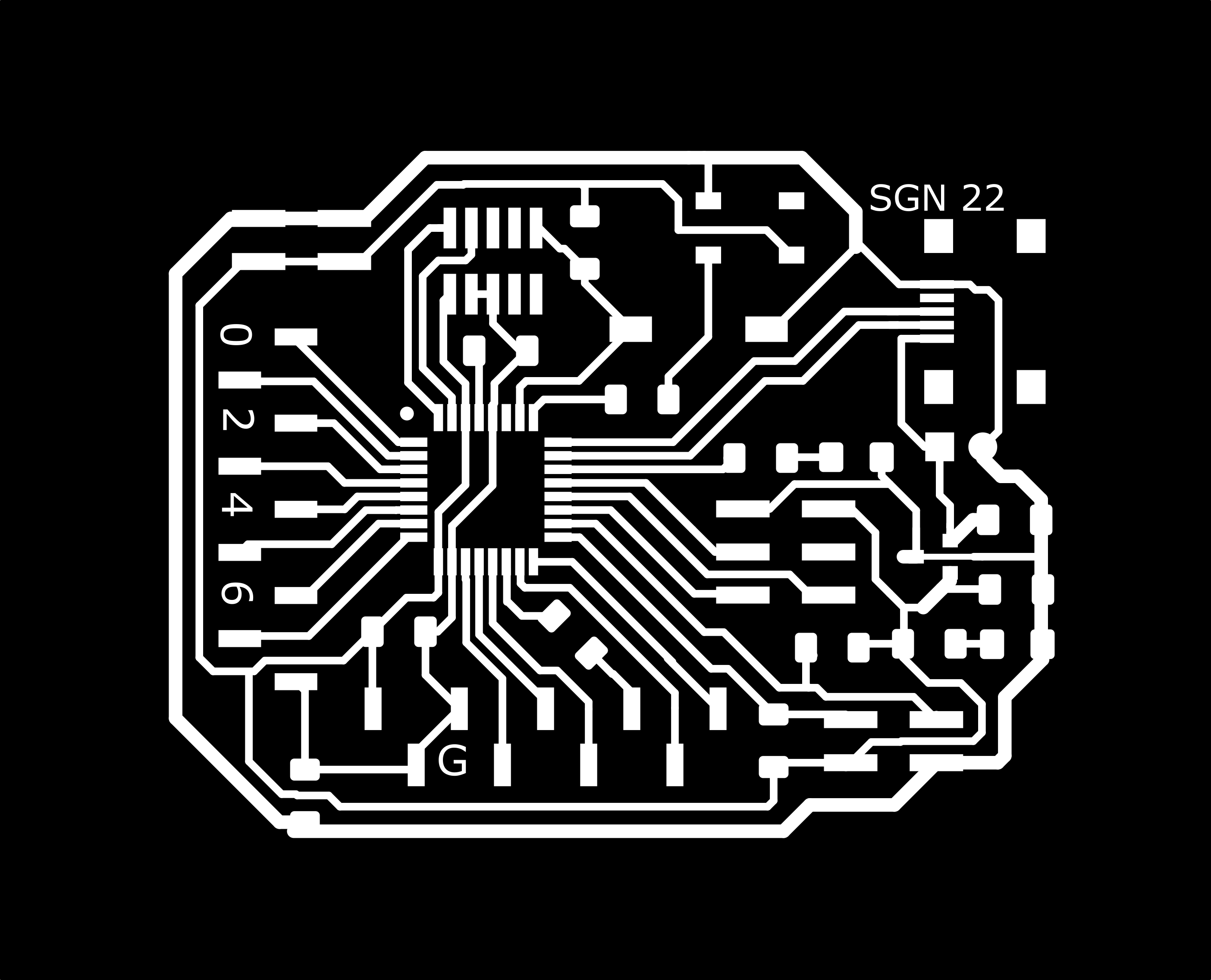
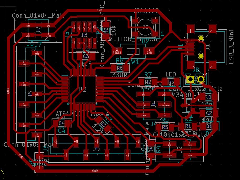
I haven’t had a chance to actually mill and make the board yet, so I’m not sure if it’s going to work or not. Caveat emptor. One thing I know is that the traces are real tight, and I’ll need to use a small endmill (smaller than a 64th, lol.) or… just lie to the CAM (ie Mods) and tell it it’s a smaller tool than it actually is and let it run with that.
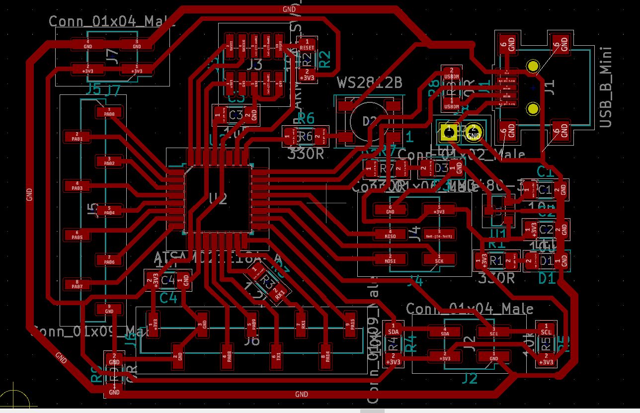
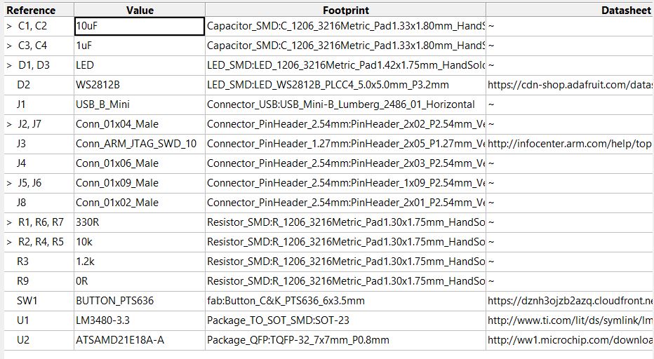
But here are the board files:
THESE FILES ARE NO GOOD, SEE BELOW
DEPRECATED : SEE BELOW
I’m only leaving these up for historical purposes. SEE BELOW FOR UPDATED FILES.

References and Resources
I based this off of three main resources:
the SAMD21 datasheet: https://ww1.microchip.com/downloads/en/DeviceDoc/SAM_D21_DA1_Family_DataSheet_DS40001882F.pdf
Quentin Bolsee’s SAMD21 dev board: https://fabacademy.org/2020/labs/ulb/students/quentin-bolsee/projects/samd21e_devkit/
and the MTM FabAcademy site on the SAMD21: https://mtm.cba.mit.edu/2021/2021-10_microcontroller-primer/fab-arduino/
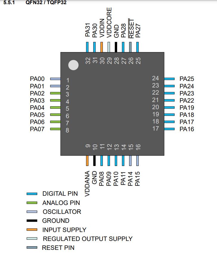
SAMD21E Pinout
Friday 5/6
In the morning started working on programming week, started with P5.js. Enjoyed it. See more at Week15.
Went it to CPCC today to help Cori with some of her projects. She made a new board and got the neopixel flashing the colors she wanted. With Adam Harris’ help, she managed to get the buttons working too (I heard.)
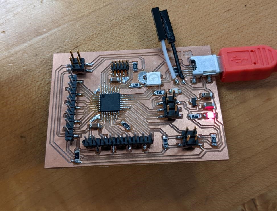
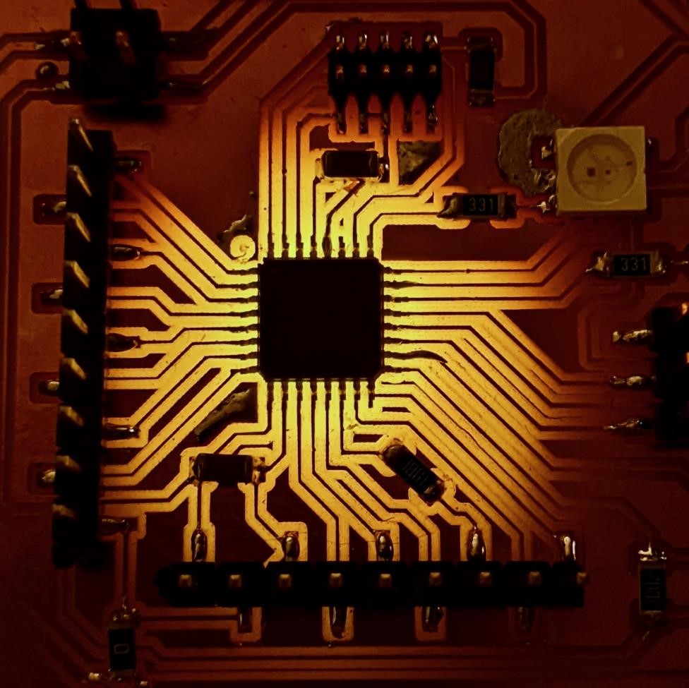
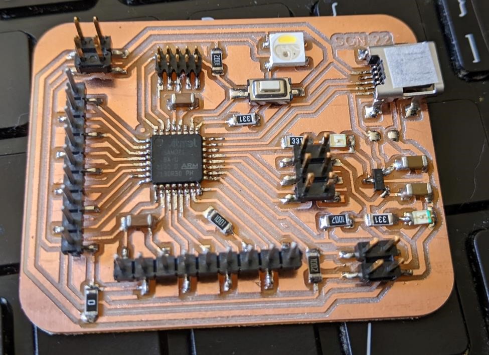
I milled and solderd a new SAMD21 board. It was a pain in the butt. Tiny traces to solder for the chip and the USB mini connector, as well as the tiny little jtag pin connector I used (which I won’t be doing again, especially as looking at the board, I have room for a 2.54mm pitch full size connector.)
The vtool I used to carve it when a bit deeper and was a bit wider than what I expected. This mean that more copper was removed than I had anticipated (but to be fair, I had also made the copper traces much wider to begin with, with the exception of one area where I had to sneak it through.)
That was the groud path. It’s a bit skinny. But it works! (I put it on the optical comparator, it was about 0.0015” wide…)
But the hardest part is programming the thing. I need a cable to convert the small size connector to full size. I made two cables, both were junky hacks, and neither work. I’m going to just resolder my own.
This took up too much of my time.
Saturday 5/7
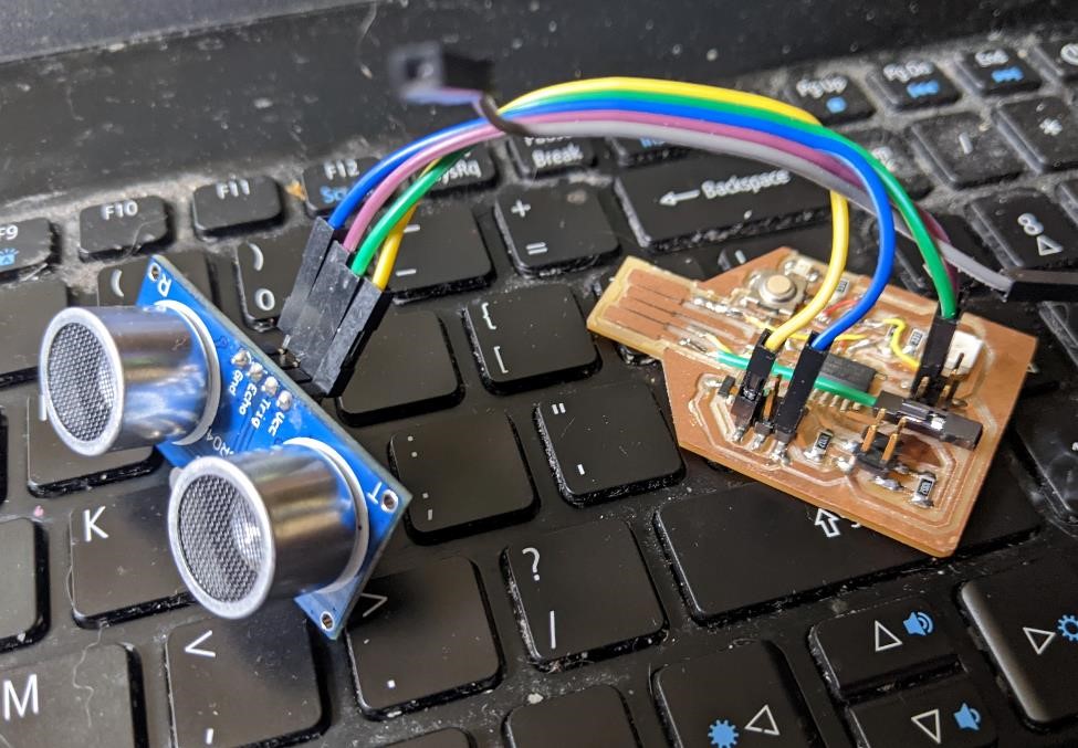
HCSR04 sensor
Very quickly plugged up an HC-SR04 ultrasonic sensor to a SAMD11 board and got it working by copying and pasting code with usual minor modifications (switch pin numbers, switch Serial out for SerialUSB.) And it worked well. It’s nice when things actually take no time to do and they work the first time.
Pinout was PA30 (phys pin 7) for trigger, and PA31 (phys pin 8) for Echo. 3.3v and GND of course.
Here’s the modified code, which was based from this website: https://randomnerdtutorials.com/complete-guide-for-ultrasonic-sensor-hc-sr04/
/*
 * created by Rui Santos, https://randomnerdtutorials.com
 *
 * Complete Guide for Ultrasonic Sensor HC-SR04
 *
    Ultrasonic sensor Pins:
        VCC: +5VDC
        Trig : Trigger (INPUT) - Pin11
        Echo: Echo (OUTPUT) - Pin 12
        GND: GND
 */

int trigPin = 30;    // Trigger
int echoPin = 31;    // Echo
long duration, cm, inches;

void setup() {
  //Serial Port begin
  SerialUSB.begin(0);
  //Define inputs and outputs
  pinMode(trigPin, OUTPUT);
  pinMode(echoPin, INPUT);
}

void loop() {
  // The sensor is triggered by a HIGH pulse of 10 or more microseconds.
  // Give a short LOW pulse beforehand to ensure a clean HIGH pulse:
  digitalWrite(trigPin, LOW);
  delayMicroseconds(5);
  digitalWrite(trigPin, HIGH);
  delayMicroseconds(10);
  digitalWrite(trigPin, LOW);

  // Read the signal from the sensor: a HIGH pulse whose
  // duration is the time (in microseconds) from the sending
  // of the ping to the reception of its echo off of an object.
  pinMode(echoPin, INPUT);
  duration = pulseIn(echoPin, HIGH);

  // Convert the time into a distance
  cm = (duration/2) / 29.1;     // Divide by 29.1 or multiply by 0.0343
  inches = (duration/2) / 74;   // Divide by 74 or multiply by 0.0135

  SerialUSB.print(inches);
  SerialUSB.print("in, ");
  SerialUSB.print(cm);
  SerialUSB.print("cm");
  SerialUSB.println();

  delay(250);
}
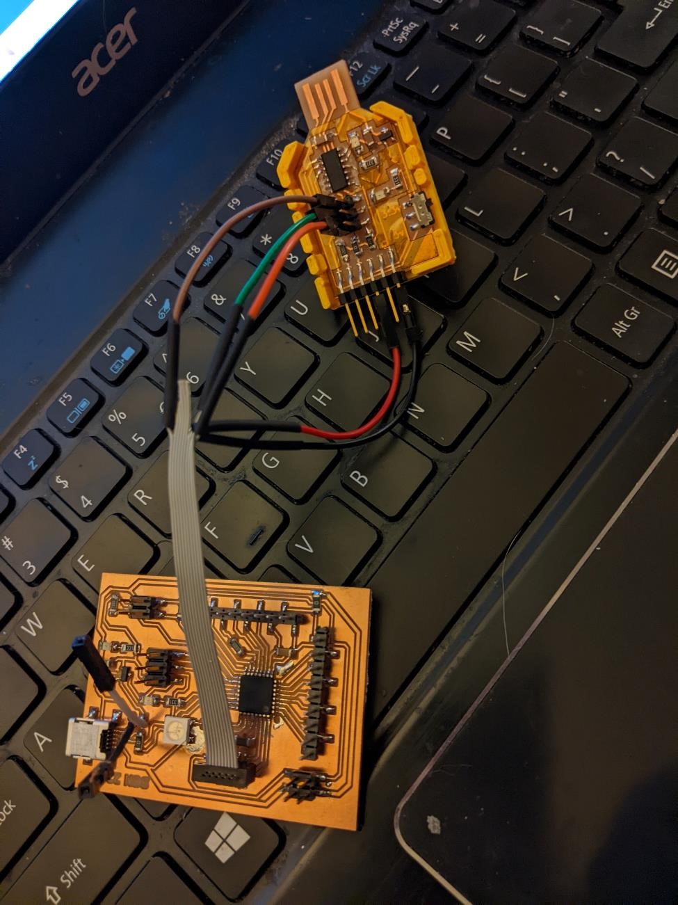
JTAG Cable and SAMD21 Board
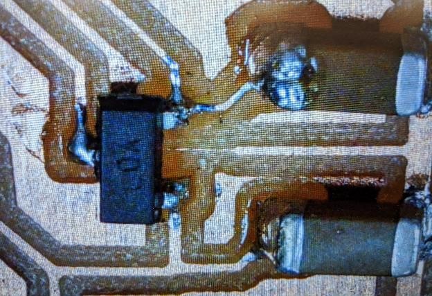
Played around with the JTAG ARM cable, and discovered that one of the small 1.27mm pin headers was shorting out gnd and power. This took about 30 minutes to diagnose, and after I’d made a number of alterations to the cabling, thinking it was some other part, and worried it was a short on the JTAG header on the board (and for all I know, that’s still a possibility.)
And for a reference, here’s the pin out that I used (the 10 pin version).
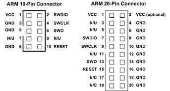
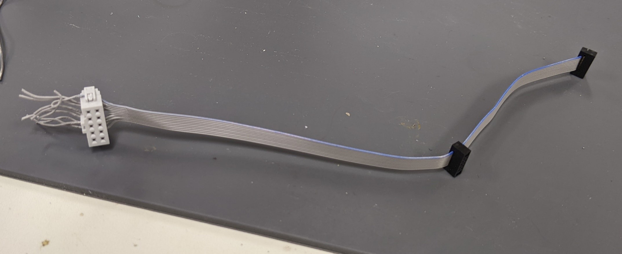
And made up a new cable.
Once I got the cable working, I programmed it with the generic SAM_BA bootloader for the SAMD21E18A. Found here: https://github.com/mattairtech/ArduinoCore-samd/blob/master/bootloaders/zero/binaries/sam_ba_Generic_x21E_SAMC21E18A.bin
And with the working cable, it was cake to program it, using the JTAG cable and the the Adam Harris programmer board.
C:\Users\Garrett Nelson\Downloads>edbg-windows-r32.exe -ebpv -t samd21 -f sam_ba_Generic_x21E_SAMC21E18A.bin
Debugger: Alex Taradov Generic CMSIS-DAP Adapter F664EF0B v0.1 (S)
Clock frequency: 16.0 MHz
Target: SAM D21E18A (Rev D)
Erasing... done.
Programming.... done.
Verification.... done.
However… when I plugged it in to the USB port, it didn’t work. I got usb errors.
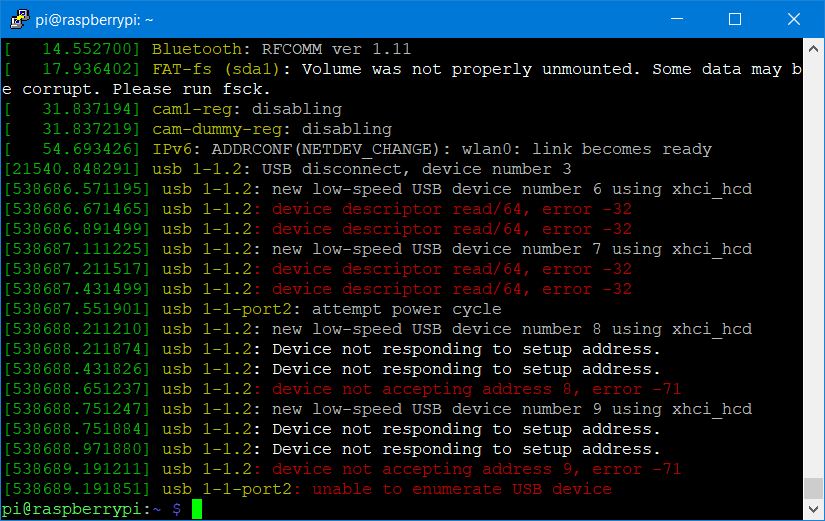
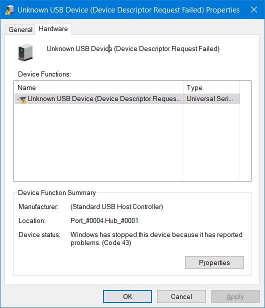
I tried tracking this error down for a while. At first I assumed it was a bad solder joint, because it was so difficult to solder the USB mini connector. So I hit it again with some solder, still nothing. And the weird thing was that it wasn’t that the USB device wasn’t seen, it was seen, it just wasn’t working. I’ll work on this problem later.
P5.js
Also spent a lot of time with P5.js today.
I had fun.

Sunday 5/8
Had to do real work, so wasn’t able to spend as much time on this as needed, but I figured out what the issue was with the SAMD21 board not being seen. Some idiot (the guy who designed the board) managed to switch the USB+ and USB- data lines. He only looked at them like 20 times to make sure they were correct, and still mananged to mess them up. Sigh.
Quickly changed this on the board, I’ll make another one when I get the chance.

update: made one and it works.
Monday 5/9
Fixing SAMD21 mistakes
Finally managed to get the samd21 board working. I had the hardest time with the USB port working consistently. It was obvious that there were issues with the connections, and a dry solder joint, a short, or something. I could bend the board and it would work briefly. I finally did this once too often and popped the USB plug right off. Interestingly, the solder joints came off perfectly, and the traces were not ripped off. But this also tells me that the solder joints were garbage.
I super glued the plug back onto the board, and I ran a bunch of traces from USB data plus and USB data minus direct to the chip. I still had issues getting this to work. After way too much time trying to fix this, I finally was able to get it to work, and heard that magical windows ping of a device being detected.
By this time, I had already messed up the vcc trace, so I had ran a wire to the power from the usb plug, and so only had to run one to ground. Then I hunted for super glue, found none, and made due with hot glue. It barely held.
And just as I got it connected and programmed it… it fell off the table and the usb plug ripped right off again.
But it all worked, and I was able to detect the COM port and program the board… once.
And I had to reset the board. I did this by using a jumper wire between ground and reset on the jtag port. I would touch these two pins together twice, very quickly. This would reset the bootloader. And everytime I did this, the device would be found again.
I finally realized that the mattech device for the samd21e18 was set for a real crystal oscillator, and as I wasn’t using one, this was causing major issues with my board.
I fixed this, and I was finally able to program the neopixel program, and it worked no problems.
Samd21 v2.
Built up the 2nd version of the samd21 board.
I milled it using a vbit, and milled it using a 0.010” tool bit size.
Suggestions:
When soldering the USB mini connector, tin the pads on the pcb, and tin the pads on the connector. Then place and solder. I had much better results this way.
Flashed it using an Adam Harris programmer board and edbg, as well as my hacky JTAG cable. Worked immediately, no problems. Just kidding.
edbg-windows-r32.exe -ebpv -t samd21 -f sam_ba_Generic_x21E_SAMC21E18A.bin
This wouldn’t connect to windows for me.
However, this one did.
edbg-windows-r32.exe -ebpv -t samd21 -f sam_ba_MT_D21E_rev_A_SAMD21E18A.bin
Then in Arduino, I set the board to “MattAirTech MT D21E (Rev A)”
The microcontroller is “SAMD21E18A”
And Clock Source is: “INTERNAL USB-CALIBRATED OSCILLATOR”
RGBW neopixels
This version of the board is using an RGBW neopixel.
I had to change the library too:
Adafruit_NeoPixel pixels(NUMPIXELS, PIN, NEO_RGBW + NEO_KHZ800); // RGBW neopixel
and then add a ‘W’ element to all the setPixelColor, such as…
pixels.setPixelColor(0, pixels.Color(150, 0, 200, 0));
and that’s that. the last number is the brightness of the white pixel.