4. Computer controlled cutting
February 9, 2022
This week is about using a laser cutter and a vinyl cutter.
Vinyl Cutting
I have never used a vinyl cutter before, and this was my first time. I worked with Denny Leak (and I’m very appreciative of his help.), and together we set up and got the Roland GX-24 vinyl cutter to work through Inkscape.
Our success was largely due to this video from Fab Lab Barcelona, which essentially walked us through the entire process: https://www.youtube.com/watch?v=8oCOzy_Zx2o
And the FabAcademy documentation: https://fabacademy.org/2019/docs/FabAcademy-Tutorials/week03_computer_controlled_cutting/rolandgx24.html
Basic Instructions on setting up and using the Vinyl Cutter.
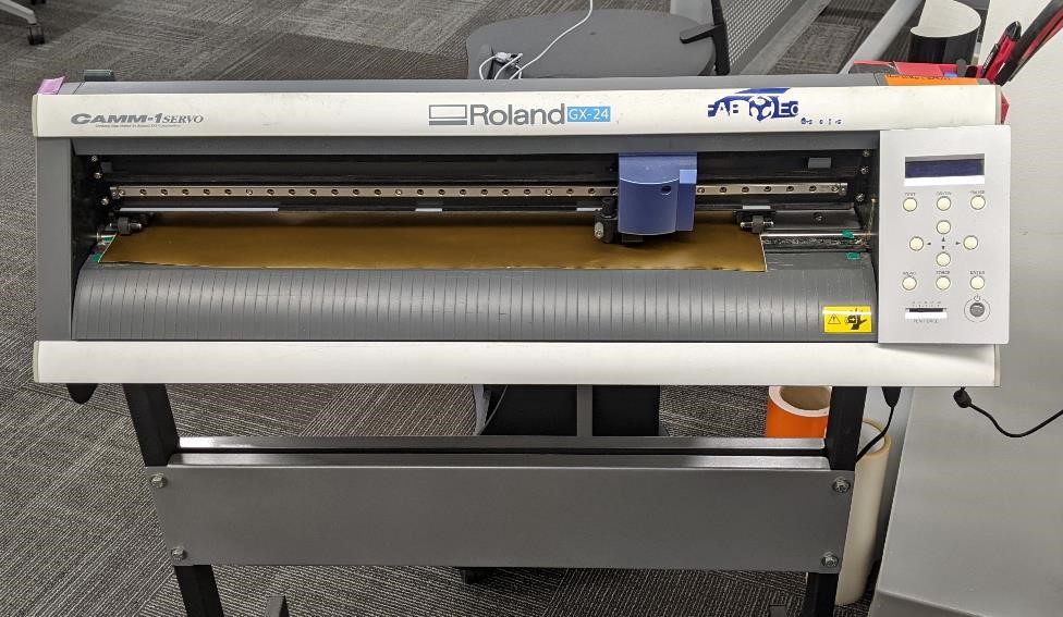
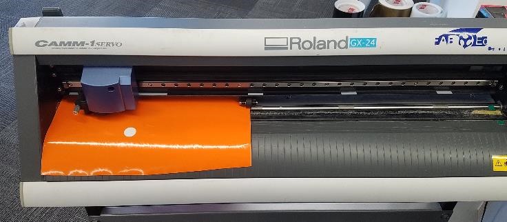
The Roland GX24 Vinyl Cutter at CPCC Fab Lab
Setting Up the Vinyl Cutter
-
Install Roland GX-24 Drivers.
-
Set up the blade for the cutter.
-
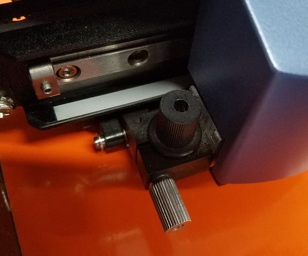
On the left of the cutting head, there is a small thumbscrew. Un-tighten this screw and pull the blade holder out of the head. The holder is a black piece of plastic about an inch long and half an inch in diameter. (The Cutting Head and Blade Holder. Images Courtesy of Dennis Leak)
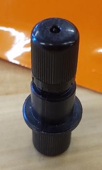
(The Blade Holder. Image Courtesy of Dennis Leak)
- I suggest using a magnifying glass and make sure the blade is not broken.
- To replace the blade, you can unscrew the holder apart and remove the steel blade and replace it with another blade. Screw holder back together.
- You must now adjust the blade holder. You do not want the blade sticking too far out of the holder, or to be too recessed.
- To test, place a piece of your vinyl on a flat surface (and a surface you don’t mind scarring), and apply firm pressure and drag the blade across the vinyl sample. If the blade cuts through the backing paper, you want to retract the blade. If the blade doesn’t seem to cut deep enough, extend the blade. The blade should be about 0.015” above the mouth of the blade holder.
-
Reinstall the blade holder in the cutting head, and tighten down the thumb screw.
-
Install your vinyl.
-
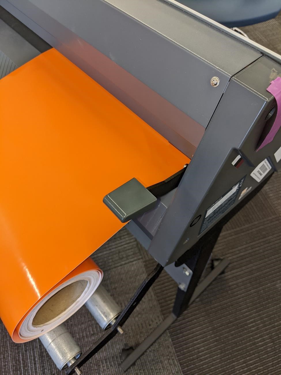
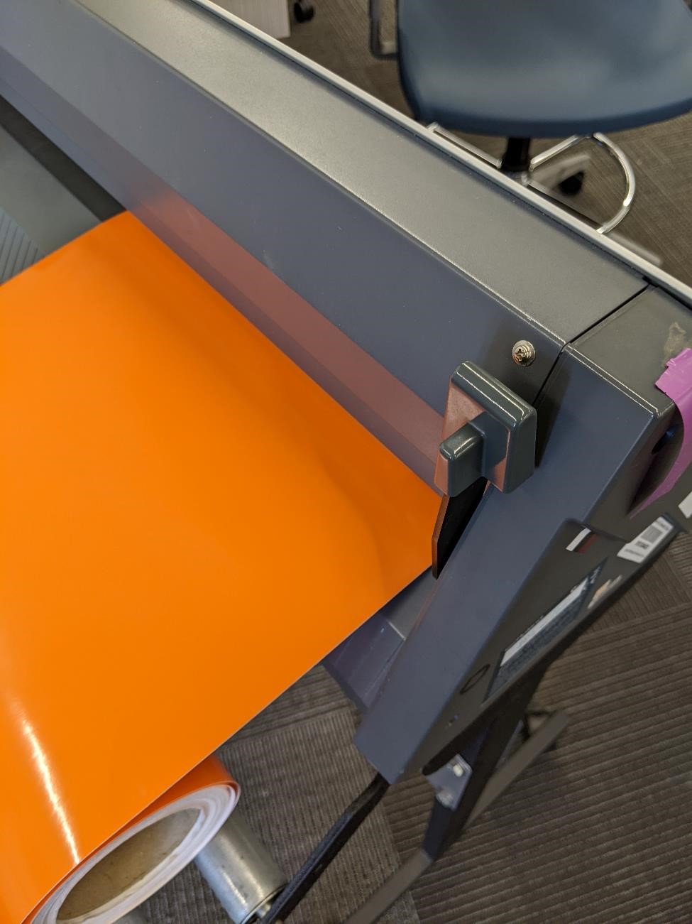
Put the Vinyl through the back, and align on the left side (looking at it from the front.)
-
Lock vinyl in place with lever on back left.
-
Important! There are guiding wheels, and they must be in the proper place in order for cutter to work. There are 2 to 3 wheels. They must be aligned with grey/white stripes on the guide surface (just above the vinyl and wheels). One wheel must be in the long white stripe at the far left, and one wheel must be in the shorter white stripes further to the right.
-
Power on the Roland GX-24.
-
Select “Roll” and press enter. Note if the vinyl and wheels aren’t set correctly, this may not work.
-
To setup your Roland GX-24:
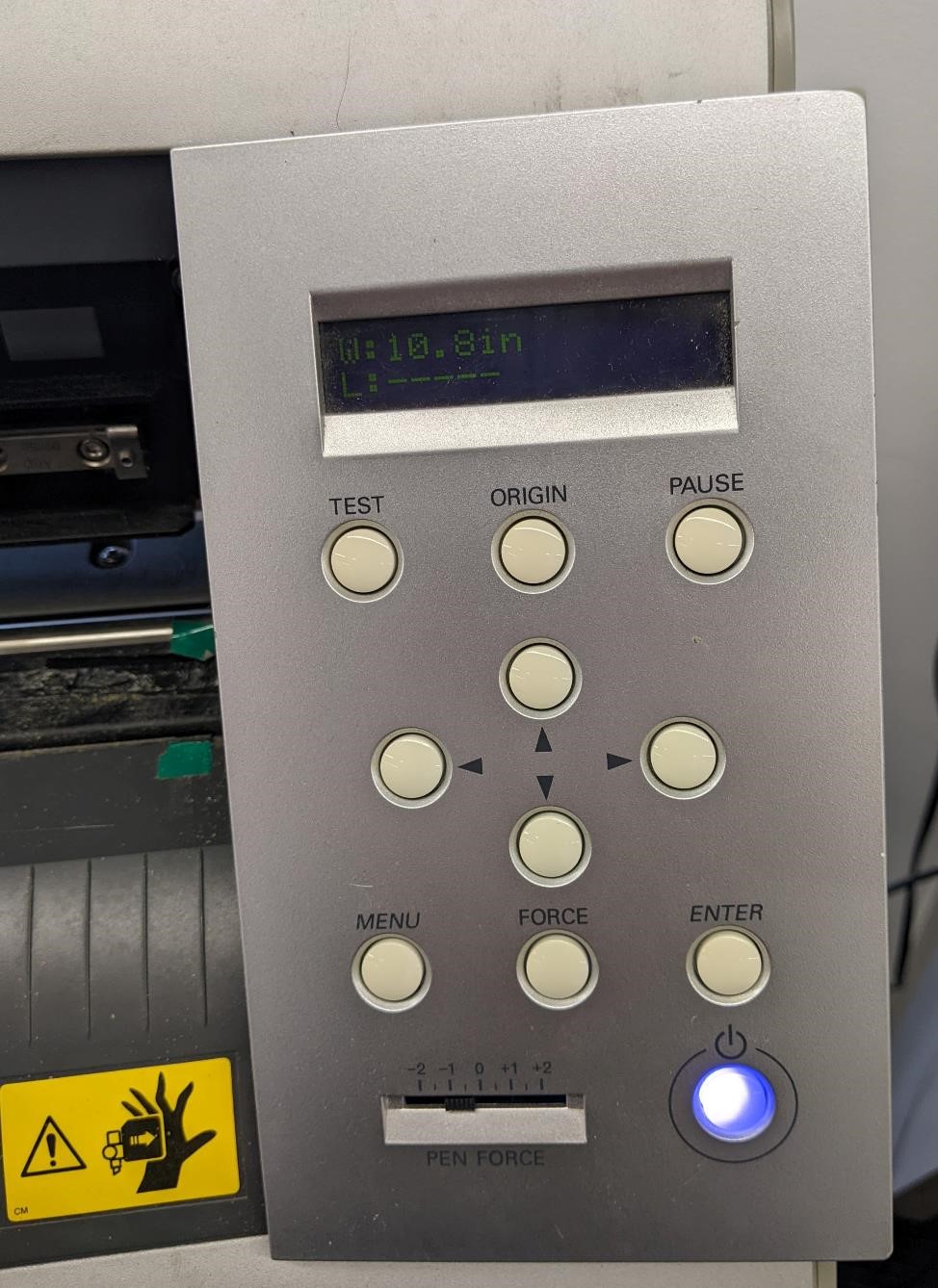
- Press the “MENU” button twice. It should say “Unsetup”
- Press “DOWN” arrow key to “Condition” and then press “RIGHT” arrow key.
- Press “RIGHT” arrow key to “Force”
- Press “RIGHT” arrow to change.
- Then Press “UP” or “DOWN” arrow key to change the Force. Press “ENTER” to select. Our cutter was set to 130 gf.
- Then Press “DOWN” arrow to select “SPEED.” “RIGHT” Arrow to change, and “UP” and “DOWN” to change speed. “ENTER” to select. It was set to 9cm/s.
-
Press “MENU” twice to get back to main system.
-
Press and hold the “TEST” button for 2 seconds. It will print a small circle with a square inside. This is a test piece. Try taking it off the backing paper, if you cannot easily, or it rips, you may wish to change either the cutting force, or extend the cutting blade out farther from the face of the holder.
-
We had good results with 120gf of Force, 9 cm/s Speed, and 0.250. However, it’s likely you’ll need to change the force with different vinyl materials. This is trial and error. The “TEST” button is great for dialing this in.
Preparing Inkscape File to Cut on Engraver or Laser
Assuming you have a file ready to print, these are the directions to make sure Inkscape is set up correctly to print.
-
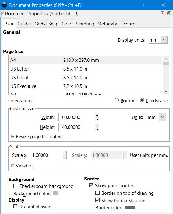
Set up Document Properties.
-
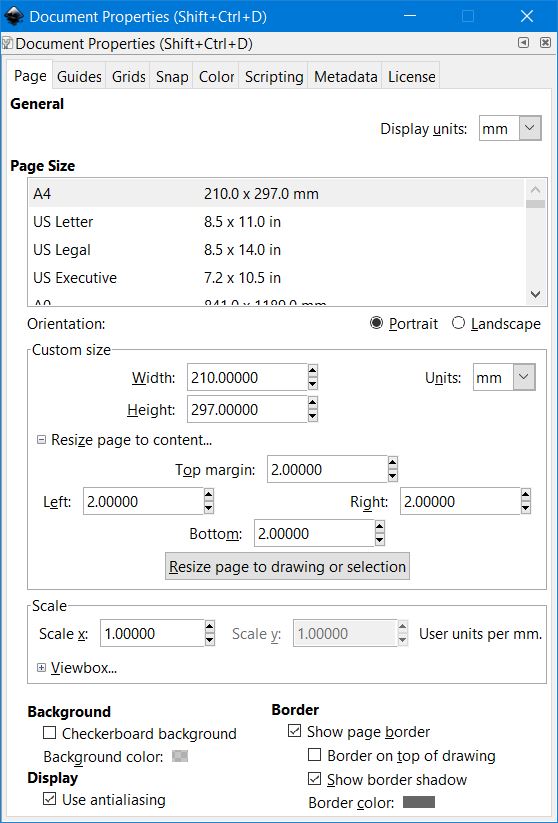
Select “File” -> “Document Properties”
-
Make sure that the units are set to the same units that the Roland GX-24 is using. I believe ours defaulted to Metric (mm).
-
Also make the size of the document (the Width and Height) is slightly larger than the design you are cutting, if this is not the case, it may not cut the design at the edges. An Easy way of doing this is clicking “Resize Page to content” and adding a 2.0mm margin on each side of the drawing. Then click “Resize page to drawing or selection.”
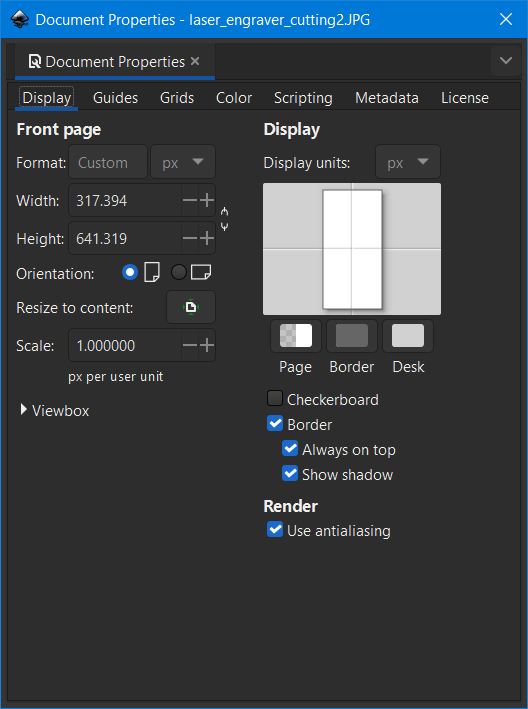
UPDATE: Inkscape has changed this dialog in Version 1.2, it looks and behaves differently. There is still a “resize to content” box, but as of now, I don’t know how to add margins to the entire design. You may need to add extra space around the design, and drag it close to the center.
New Inkscape Document Properties Image:
-
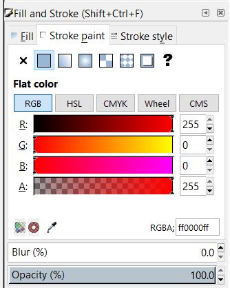
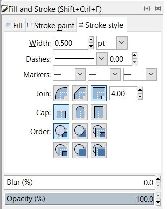
If you are cutting a vector (that is a line drawing), you need to change the lines to Red and 0.5 pt stroke weight.
-
Select “Object” -> “Fill and Stroke”
- Select the path/lines of your image and change the fill to “no fill,” the “stroke paint” to Red (255,0,0 or ff0000ff) and the stroke style to “0.50 pt”. See below Images.
-
You can now go to “File” -> “Print” and print to the “Roland” printer. The vinyl cutter should start to cut your shape out.
-
For the Laser Cutter, save your file as a plain SVG.
Using Inkscape to convert a raster file to vector
I had a couple of raster files that I created using Structure Synth that I wanted to turn into vectors so that I could use them on the vinyl cutter and the laser cutter.
But to cut them out, they need to be converted from the raster format (in this case a .jpg) to a vector image format, such as an .svg.
The below should help with showing how to turn a raster into a vector using Inkscape.
The images below were taken from a Structure Synth model created by Ankur Pawar and found here: https://sites.google.com/site/workofap/structure-synth/tree-synth?authuser=0 They were just barely modified by myself.
You can use many different types of software to convert from raster to vector. I choose to use Inkscape.
1 .Open a new Document.
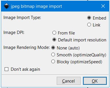
2 .Go to “File” -> “Import.” You may see an option box. I choose “Embed” and “default import resolution.” But this depends on what file you are importing. Click “OK.”
You should see your image now. You may wish to change the document size. Select “File” -> “Document Properties.” (see above “Preparing Inkscape to Cut” for more info.)
-
Then select “Path” -> “Trace Bitmap”
-
When the Dialog box pulls up, select “Live Preview” near the left-mid, bottom.
Then you will want to choose which method to create your vector. A couple of the default options are shown below.
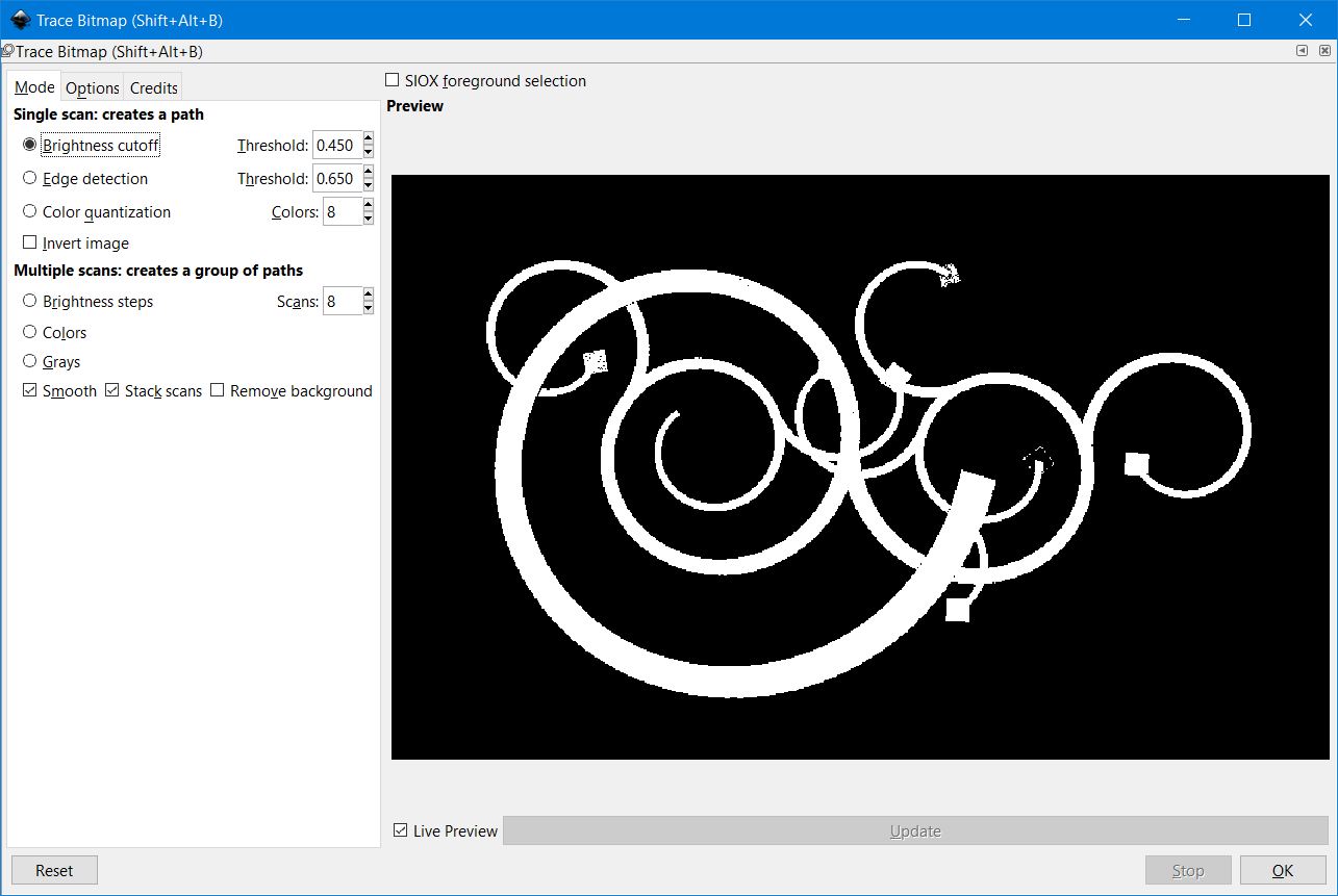
Brightness Cutoff
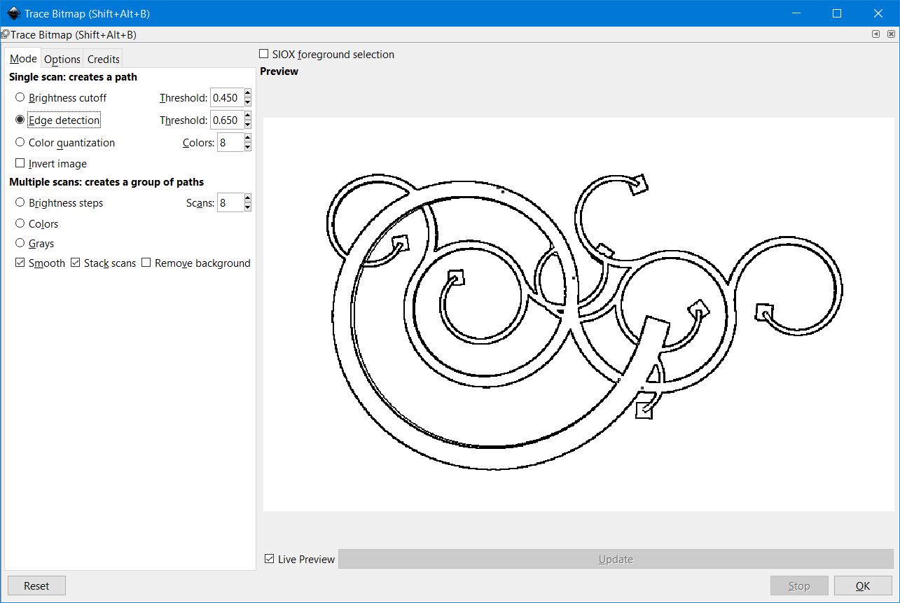
Edge Detection
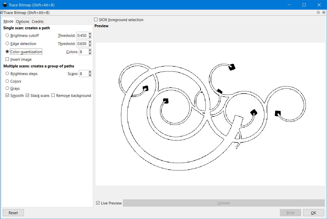
Color Quantization
- After you have chosen which style you believe works best for your design, click “OK.”
And then close the dialog window.
- You may not see the path, as it may be hidden by the original image. Click and Drag to see the outline/trace/body of your image.
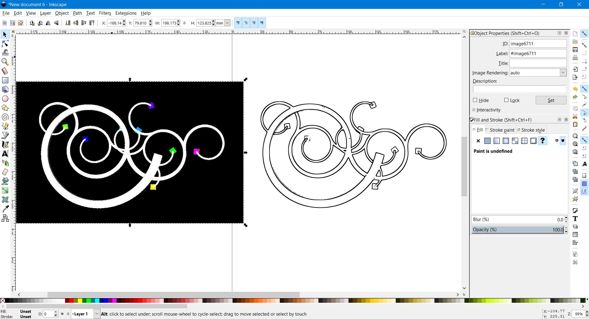
The original and the result, side by side. I had to move the original to the left as they were overlayed one atop another.
Final Cleanup
When you zoom in on your path, you may seem some errors, issues, or areas that you want to clean up.
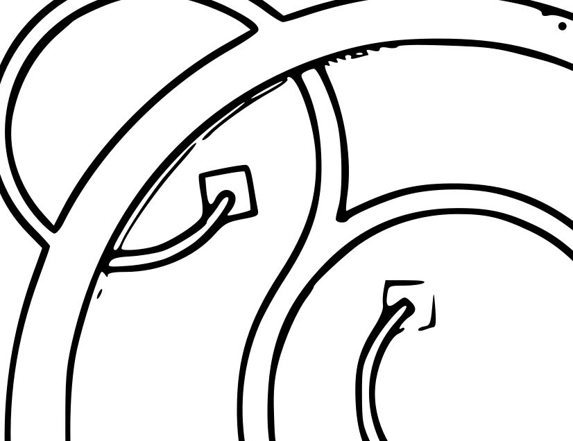
This drawing needs a bit of cleanup. But when you change you remove the fill, and change the line weight, it needs more than you may suspect.
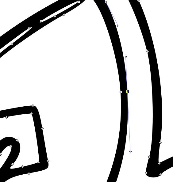
This is when you can select the paths that you have just created by double clicking, and manipulating the “squares” and “handles.” You can delete extraneous points/nodes (the boxes) and you can click and drag the circles (handles) to change the shape and curvature of the lines.
Also, don’t forget to change to change the lines to Red and 0.5 pt stroke weight.
- Select “Object” -> “Fill and Stroke”
- Select the path/lines of your image and change the fill to “no fill,” the “stroke paint” to Red (255,0,0 or ff0000ff) and the stroke style to “0.50 pt”. Again, see above “Preparing to Cut with Inkscape” for more info.
Now we see the outside and inside lines that came from the style of vector model we chose. This is an issue if we wish to cut the entire part out of vinyl for two reasons. A) It will take longer, and B) the sticker will be very thin, hard to weed, and easy to break, as well as hard to see.
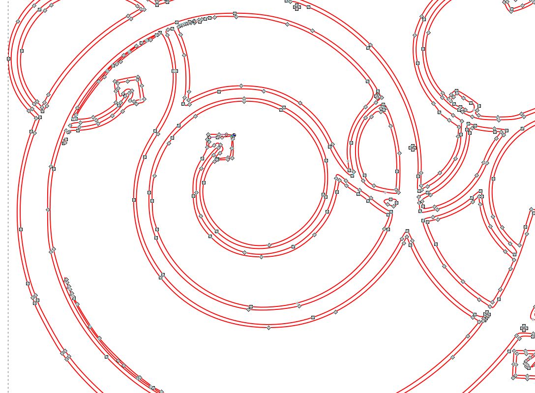
If you try to select a line, it will select the whole model. You can select each point and delete them individually, but this is a lot of work. An easier solution is to go to “Paths” -> “Break Apart.” This separates each continuous line into it’s own object, and makes removing extraneous lines much quicker. (Found this here: https://graphicdesign.stackexchange.com/questions/83990/how-to-remove-inner-stroke-in-inkscape
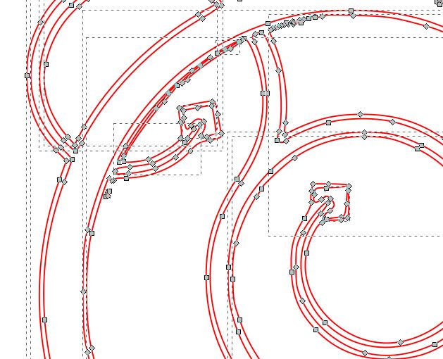
Note all the dashed lines indicating the different objects.
There is sometimes a large amount of hand finishing required to get a good line drawing ready for any type of vector operation (vinyl, laser, etc.) But sometimes, after a few minutes of work, you have a much cleaner model, ready for vinyl cutting.

After a couple of minutes, much cleaner lines ready for cutting. There’s still one obvious issue with the square in the center. That will require adding nodes to connect a line, and then erasing some other inside nodes.
And you are now ready to send the file to the Vinyl Cutter to be cut.
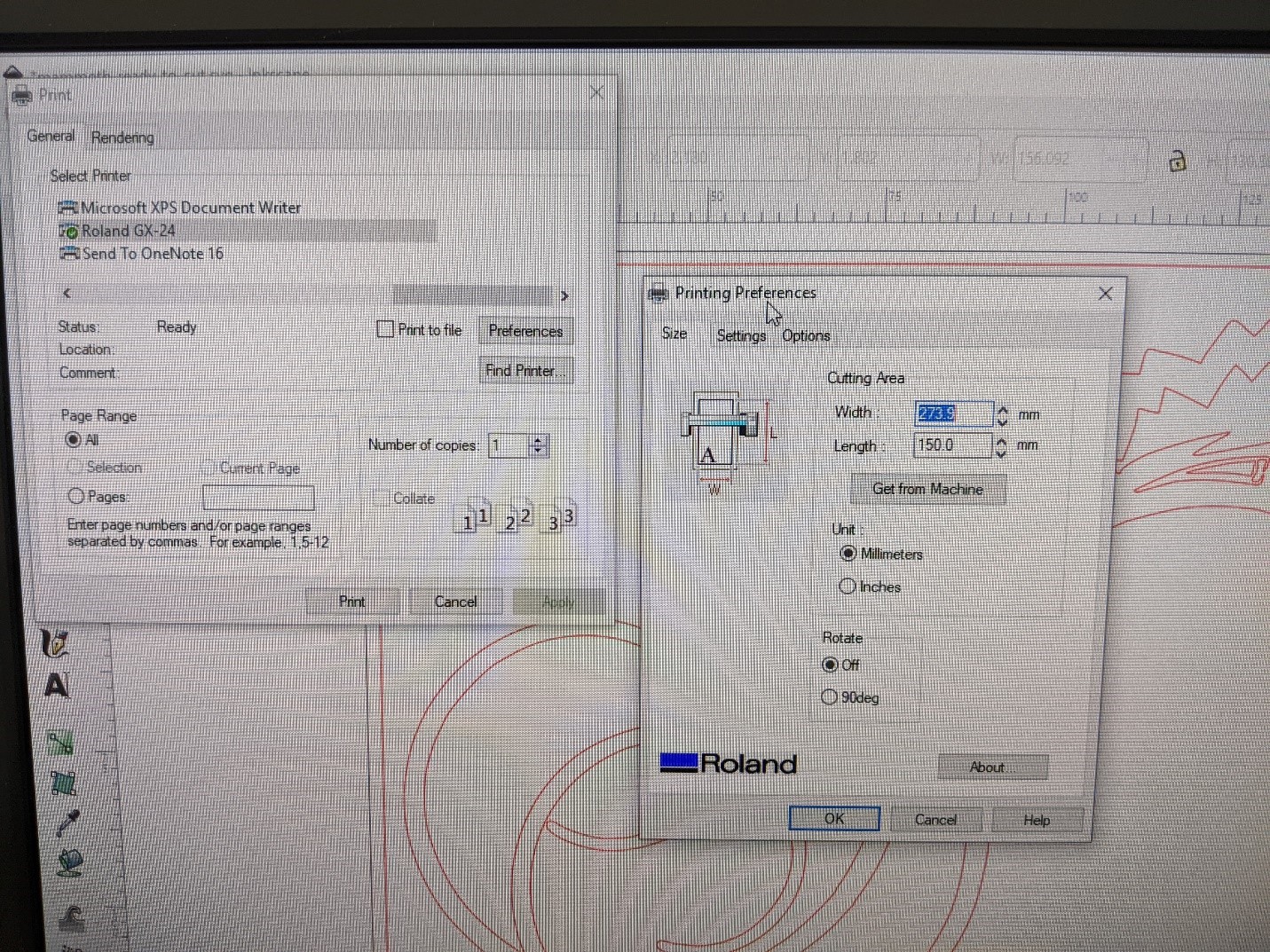
And Cut!
UPDATE! I noticed that it now wants to spool out meters of vinyl if you do not check the size of your document, and enter in the correct document properties for the length of your design. I add a few millimeters extra (say 5mm) as well. Then click “okay.”
Simply choose “File” -> “Print.” Double check your document properties for size, and then choose the vinyl cutter “Roland GX24” and it should start cutting. If there are any issues, use the “Pause” button on the Roland GX24.
My first cut.
It’s a star.

Vinyl Cutter Design Files
These are the files I used. I changed the line color to white so that you can see them against the background of the website. But you should change it to Red in order to cut them.


And an image of a design:
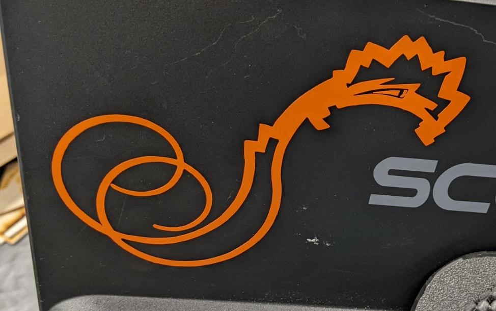
Cori taught me how to use the transfer paper. Thanks Cori.
The Laser Cutter
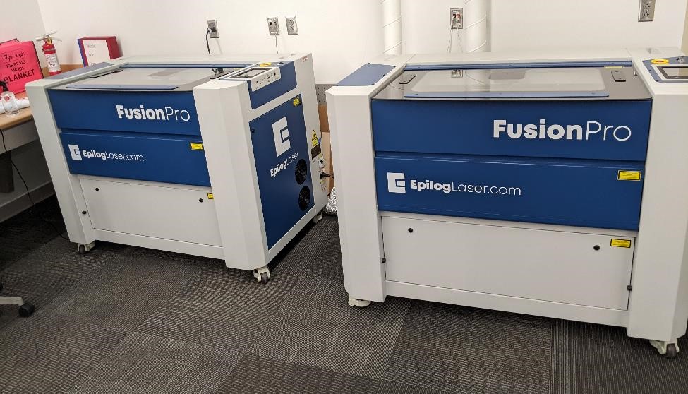
This is the first time I have used the lab’s new Epilog Fusion Pro 32 laser engravers. They were quite simple to use. Many of the setup steps for producing a file ready to cut are similar to vinyl cutting, and with the exception of color management, the settings are very similar.
Remember to change your line stroke width to 0.1 pt, as well as the color to red (255,0,0) for cutting. But as this is a laser engraver, you can also engrave with it. If you wish to engrave vectors, you can change the color to green (0,255.0) to engrave. For other engraving tasks, you should probably change the image to grayscale.
Procedures for Using the Laser Cutter
-
First, make sure to know where the water spray bottles, fire blankets, and fire extinguisher are located.
-
Turn on the Exhaust fan (the switch for this is across the room, by the cubbies, against the wall under a cover and labelled “EX FAN 5.”
-
Make sure the baffles on the exhaust of the laser engraver itself is open (these are the black “doors” sitting on the silver tubing coming from the back of the laser engraver itself.) To open them, simply pull up. It helps to close the one of the laser engraver that is not being used.
-
Log on to a computer. (You may need an instructor or lab assistant do this for you.) The two computers closest to the laser cutters are each individually connected to only 1 of the lasers. The laser engravers are called “Left” and “Right” (with this obviously being their location.) The computer furthest is connected to the left laser, the one closest (and is actually next to the left laser) is connected to the “Right” laser.
-
Whichever computer you long on, turn on the corresponding laser engraver by inserting the key (get the key from instructor or lab assistant) and turning it to the “I” symbol (for On.)
-
On the computer, open your file that you wish to print in Inkscape. You should be able to print from a number of applications, such as Inkscape, Corel Draw, and Autocad.
-
You will want to make sure that you have thin lines, the correct color lines (red for vector cutting, green for vector engraving, and black and white images for raster engraving.) and the correct linewidth (I tend to use 0.1 pixel or 0.1 pt, 0.001” etc.) and that your document size is set appropriately. I highly suggest to make the document size larger than the actual image size, as this may cause issues with the edges of your part not being cut correctly.
Setting up your document for cutting:
Look above in the vinyl cutter section for more information on setting up your document for laser cutting. For simple things, the process is the same.
Key points: Thin line width in color red for cutting with vectors.
Click Print to Cut/Engrave
Print your file, and choose the “Epilog Engraver” from the print window, and click okay.
If this is the first time using the laser, you may need to first set up the laser with the Epilog Manager.
Laser Specs
The laser is a Epilog Pro 32 (under “Other”) It has a 120 Watt CO2 laser and No Fiber Laser It has a 32” by 20” engrave area (I would shrink this by an inche however.)
The IP Addresses for the lasers are:
Left : 10.35.160.122 Right: 10.35.160.121
Laser Setup
Sometimes the Epilog software needs to be reinitiated to get the lasers working.
To do this, open the Epilog Manager Software. Ask your instructor or lab assistant for help with this. Name the Laser according to the “Right”/”Left” dichotomy.
You may then need to close this window, and re-print your file again.
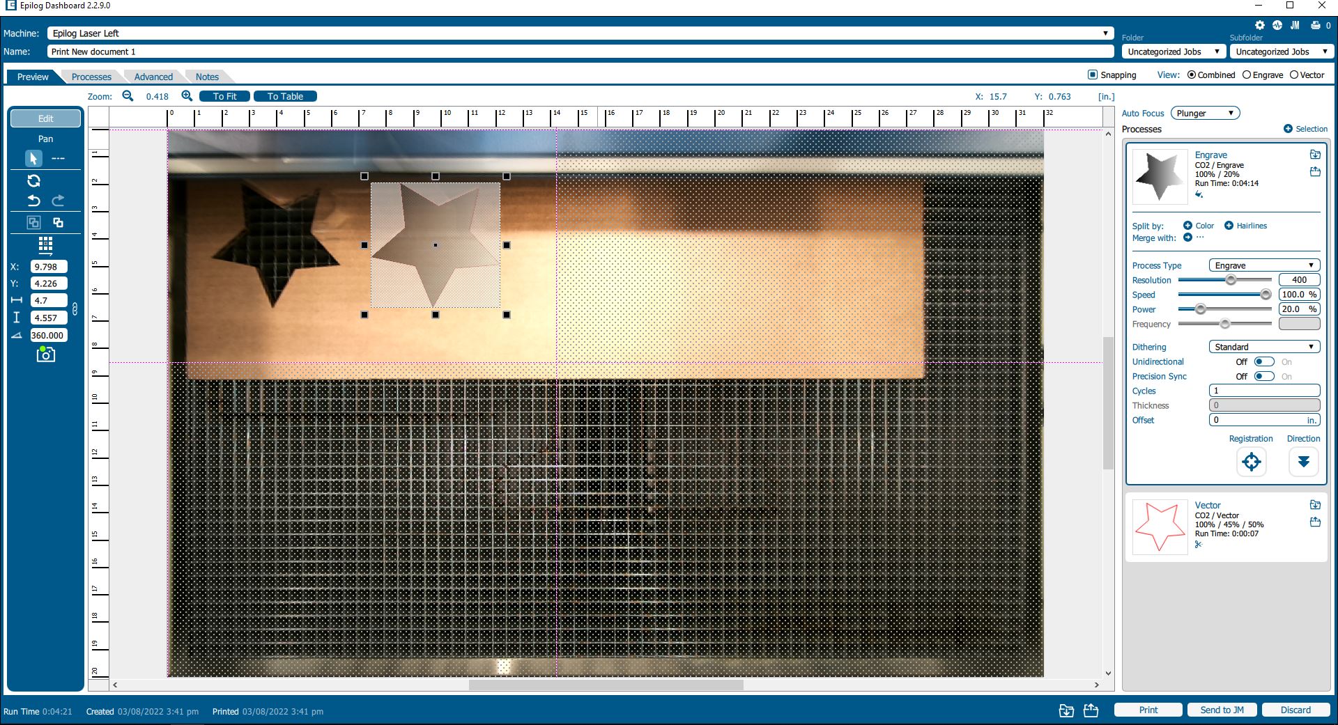
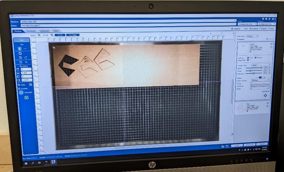
This time, you should be able to have the Epilog Dashboard laser manager window appear and you should be able to see an image of the laser table through the camera and your file.
The below is an image of the window that you should see when you “print”
Laser Speeds, Power, and Frequency Settings
These are the settings I’ve used, and I have confidence they will mostly work for cutting.
These are for VECTORs (cutting)
| Material | Speed | Power | Frequency |
|---|---|---|---|
| 1/8” cardboard | 100% | 45% | 50% |
| 1/8” plywood | 20% | 100% | 10% |
| 1/2” plywood | 4% | 100% | 10% |
See: https://fabacademy.org/2022/labs/cpcc/students/garrett-nelson/assignments/week04_group/ for more information on speeds, power and frequency.
Laser engraving/cutting process
If you have a design that requires both cutting out a part, as well as engraving a part, don’t forget to change the settings for both styles, cutting and etching. See the below two images for examples
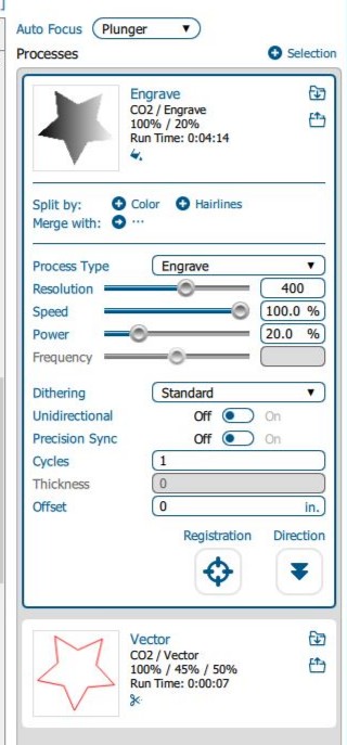
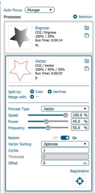
Set your speeds and feeds (power) according to the material you will be cutting/engraving.
When you have these set, click “Print.”
Move to the laser.
You can double check your work area, by clicking the tiny “laser” button (center, bottom) of the laser engravers LCD screen. This turns on a red laser (this isn’t the cutting laser, don’t worry.)
You can then press the squarish symbol button to the right (by two places) of the red laser button. This will move the laser head around and show you the work area of your part. When you’re satisfied it looks correct. Press the same button again to turn the movement off. You can also turn the red laser off.
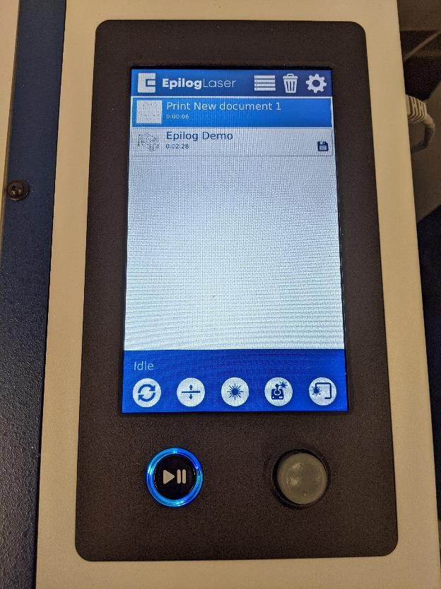
If you’re ready to go, double check your exhaust fan is working, you have some water/fire extinguishers nearby and press the “Play” button on the laser engraver.
You may wish to don the dark safety glasses. Not so much for any laser bounceback, but due to the very bright light created from the cutting.
If at any point, you think something is wrong. Press the same “Play/Pause” button to pause the laser.
When you are finished using the Laser Cutter, please turn it off, and very carefully remove the cut tray (the tray your part rests on with all the thin metal cubes) and clean out any debris left from your cuts. Small pieces of cardboard and wood are fire hazards if they accumulate.
Turn the Exhaust Fan off.
Log off the computer.
Laser Cutting Directions
-
Place the material you will be cutting/engraving in the laser engraver and close the door.
-
Center your file in the Epilog Dashboard, by clicking and dragging. Make sure that if you move it drastically, to also change the dashed-red/pink lines. This is the work area of the laser. If you forget to move these, the laser will not engrave/cut the parts that are outside of this area.
-
Set the line style to “engraving” or “vector” depending on what your design is.
-
Make sure to set the “Auto Focus” to Plunger
-
And change the Speed and Power based on the material you are cutting. See the Chart and consult the lab assistant or your instructor for more details.
-
Click Print in the epilog software (bottom right)
-
Go to the Laser Engraver, put on the dark sunglasses, and press the glowing blue/green button.
Laser Cutting pieces
Using the “Laser,” these are some of the test articles.
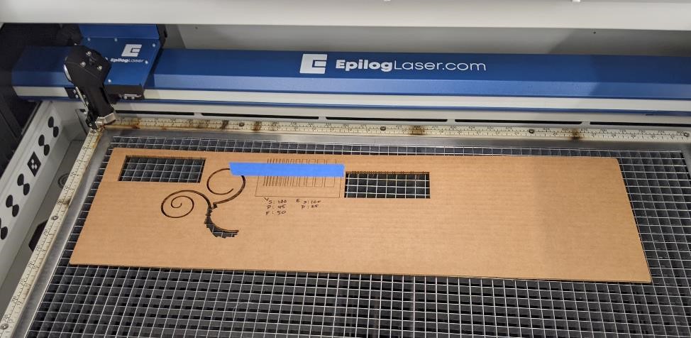
This is one of the test articles we created for testing and classifying the laser’s abilities. We made “comb” tests, which would take different cuts for different thicknesses. As an experiment, I tried one that was the opposite, to see how small we could create “fingers” without blowing them off of the main body.

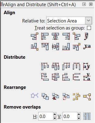
I want to point out that during this process of designing these, the Inkscape tool menu for “Align and Distribute” comes in quite handy. It allowed me to take the boxes and quickly align them so that they were even with one another, as well as to evenly distribute them across the cutting area. You can find it under the “Object” menu, or pressing “Shift+Ctrl+A” on Windows.
When you’ve done the above and you’re ready to print, you can send your file to “print,” select the laser engraver and click “print.”
Testing the laser
I started out with a couple of just random test pieces I drew in about 1 minute to help figure out how to use the laser engraving software and get a good starting point for the power and speed settings for cutting and engraving. I used information from Epilog’s manual to give me a starting reference.
The first thing I did was to draw a very simple design in Inkscape and see if I could dial in the lasers power and engraving parameters. Based on settings given from the Epilog manual, and Michael Long, our lab facilitator, I started with 100% speed 50% power for cutting and 100% speed and 40% power for engraving. This worked well for cutting, but was too powerful and cut the engraving lines through the part.
This is the Epilog Job Management software, and you can see a camera’s view of the test pieces.
When setting up the Epilog laser cutter:
- Make sure that you have your document properties set in the correct units.
- Make sure that your document area is similar to the area of your project (easy to forget to do this.)
- Set up the colors and line width for your print. Red for Cut, Green and grayscale for engrave.
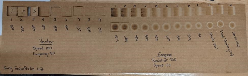
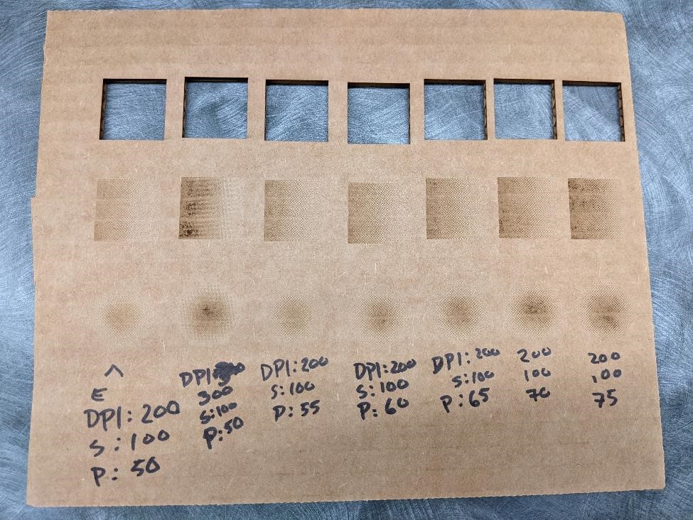
Once I found that a good value for cutting was 100% speed, 50% power and 50% freq; and that for engraving, 100% speed, 25% power and 50% freq was close to the correct parameters (at least useable results,) I designed some images for creating test pieces to better characterize the laser cutter. You can read more about this on the CPCC FabLab’s group page. One of the main test pieces.
It was easy to burn through the cardboard with more powerful settings. But it was also interesting to note that burn through was affected by the underlying corrugation pattern.
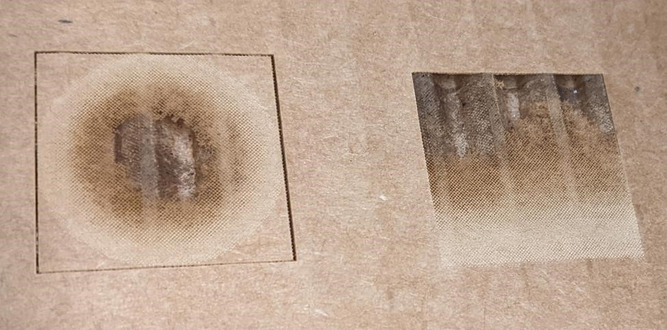
Here’s an up close image of an engraving that used a more powerful setting of 50% power. You can see the burn through of the areas that are completely black (the center and top respectively). What’s interesting is that you can also see the dithering effect and the halftone pattern in these images. (And for more about dithering, see: https://en.wikipedia.org/wiki/Dither
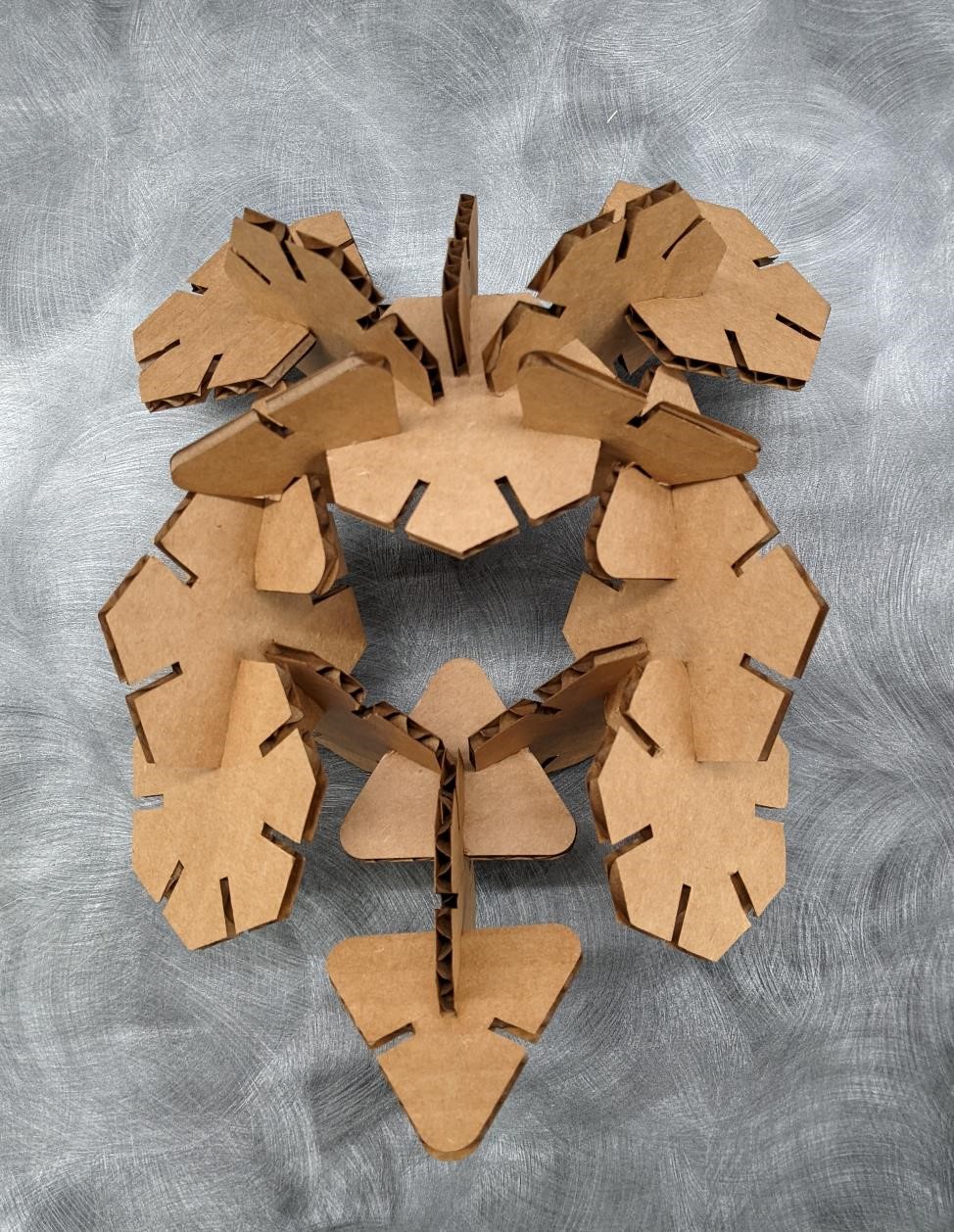
The Parametric Cuts
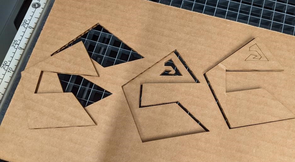
I created a set of 3 geometric shapes in Fusion 360 for this week’s assignment. Not original, but I wanted to make a box, so it’s better than that.
I made three shapes, one triangle, one hexagon, one septagon.
I quickly modeled these in Fusion 360 and used parametric modeling to be able to change the size of the slots.
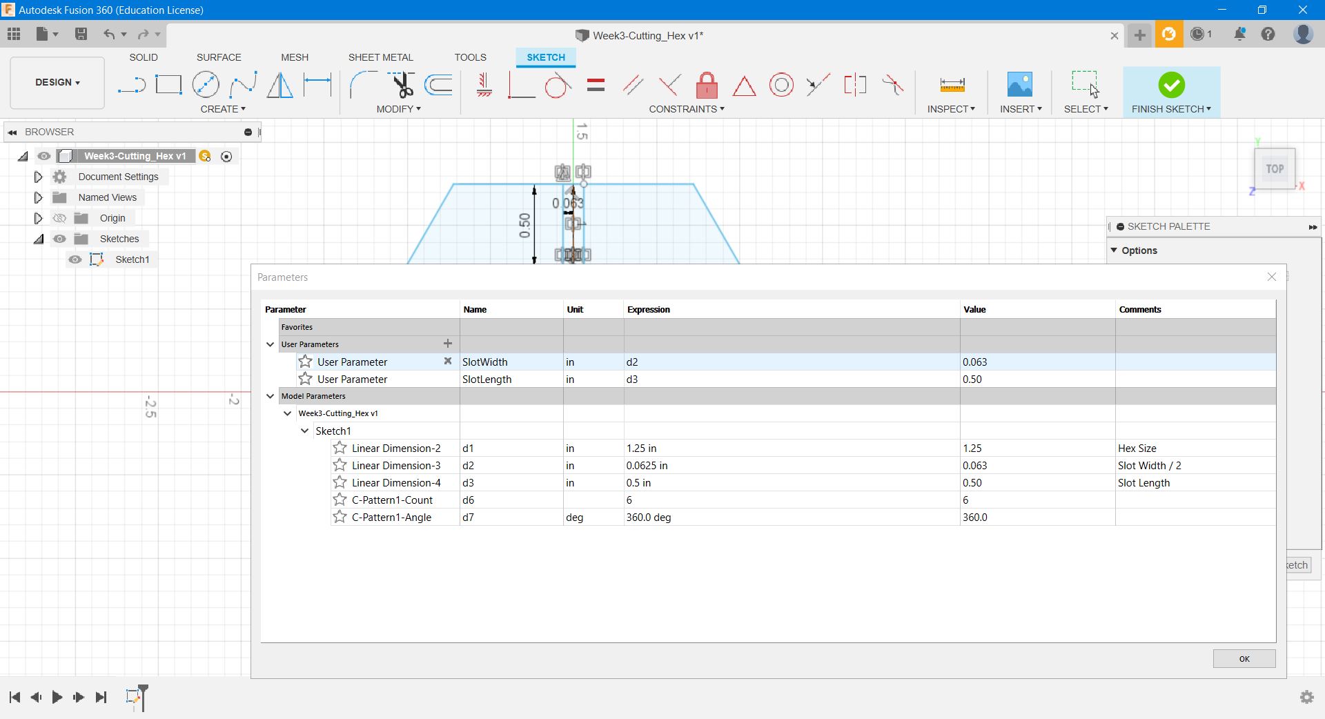
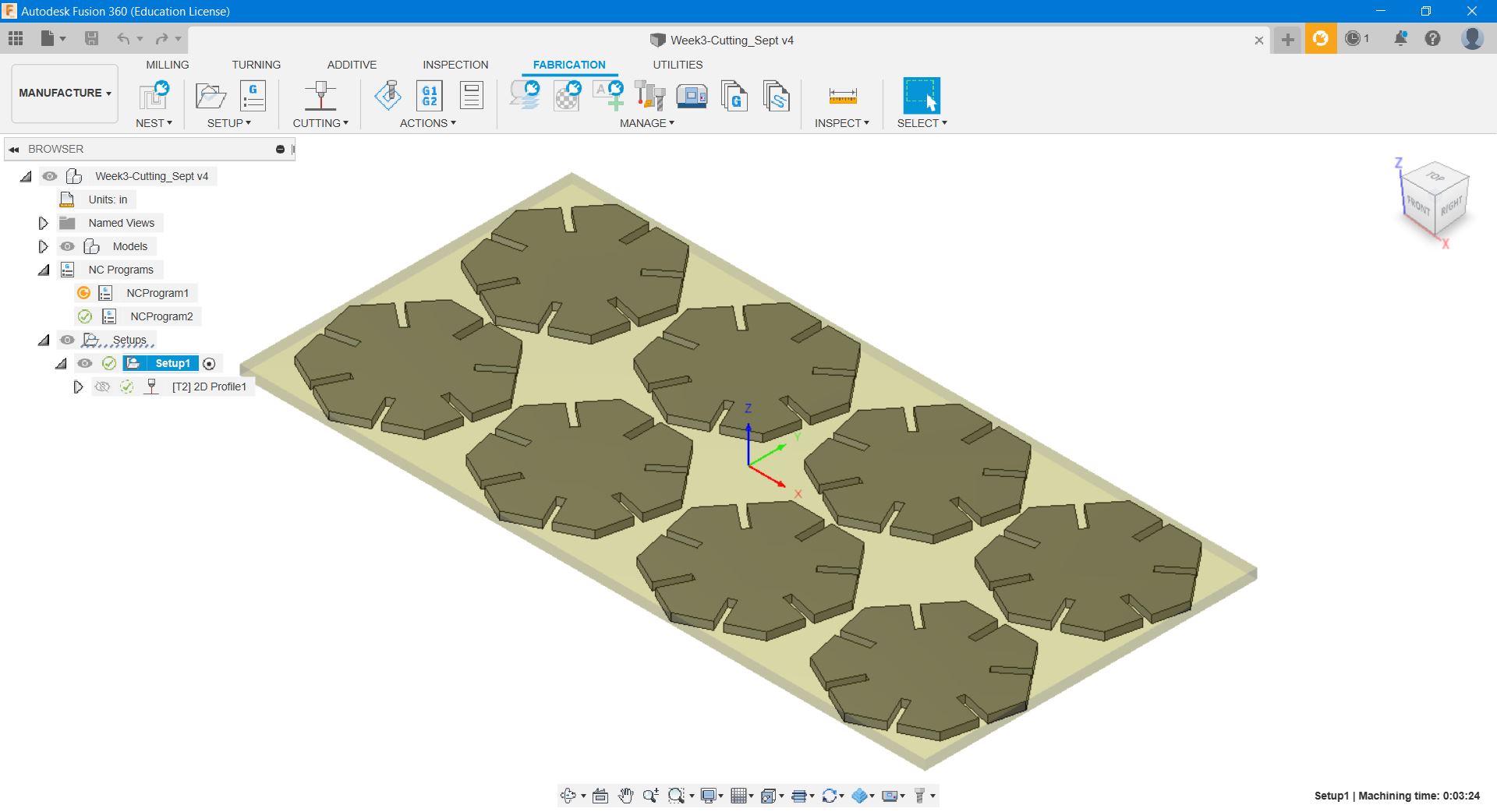
Then after that, I laid out multiple copies of the body and then I used Fusion 360’s manufacturing space to create the cut lines for this. There is no easy way that I have found to send Fusion 360 files directly to the Epilog Laser, so this is quite the pain in the butt process.
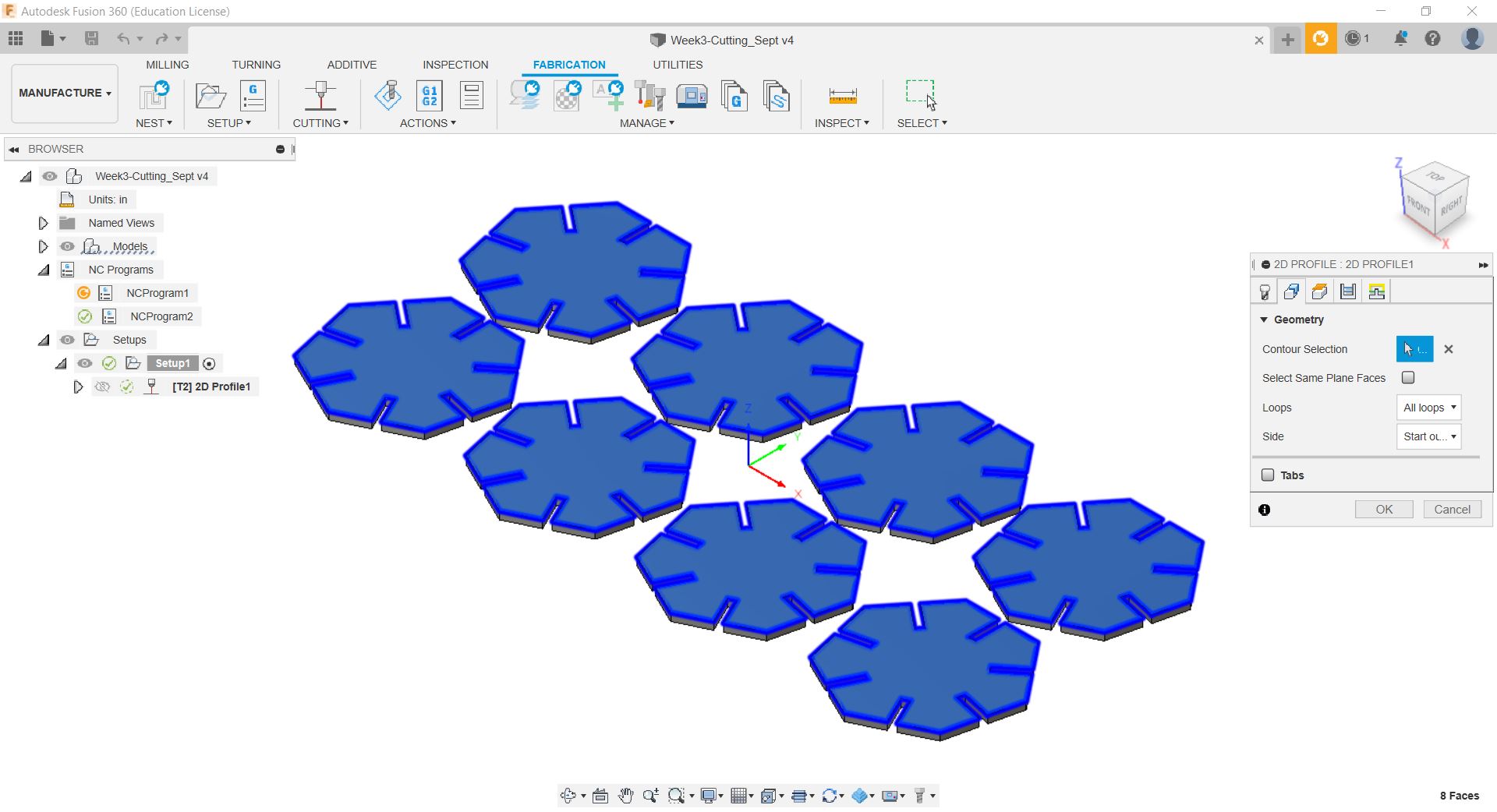
The key is to output this file using the “Universale Laser” Post, which simply outputs a DXF file. It’s not the best thing, but it is a workaround. Then send the file to Inkscape to be “printed” to the epilog laser.
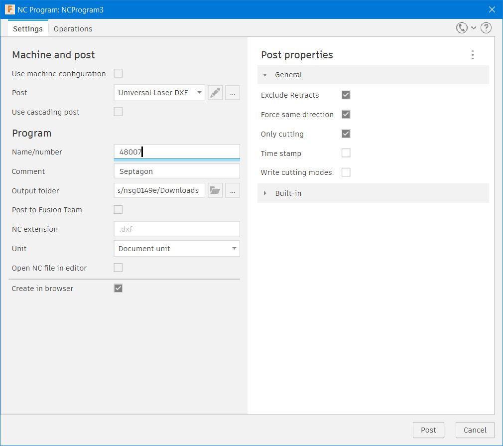
Then just “print it” and cut it by normal means.
Fusion 360 design files
You can find the Fusion360 files for this project here:
The Hexagon, The Septagon, and The Triangles
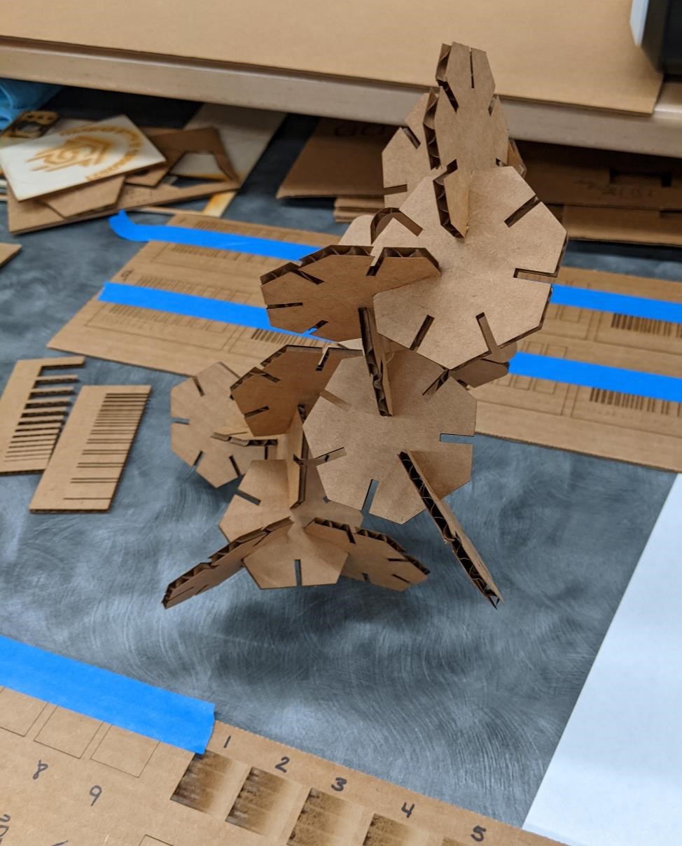
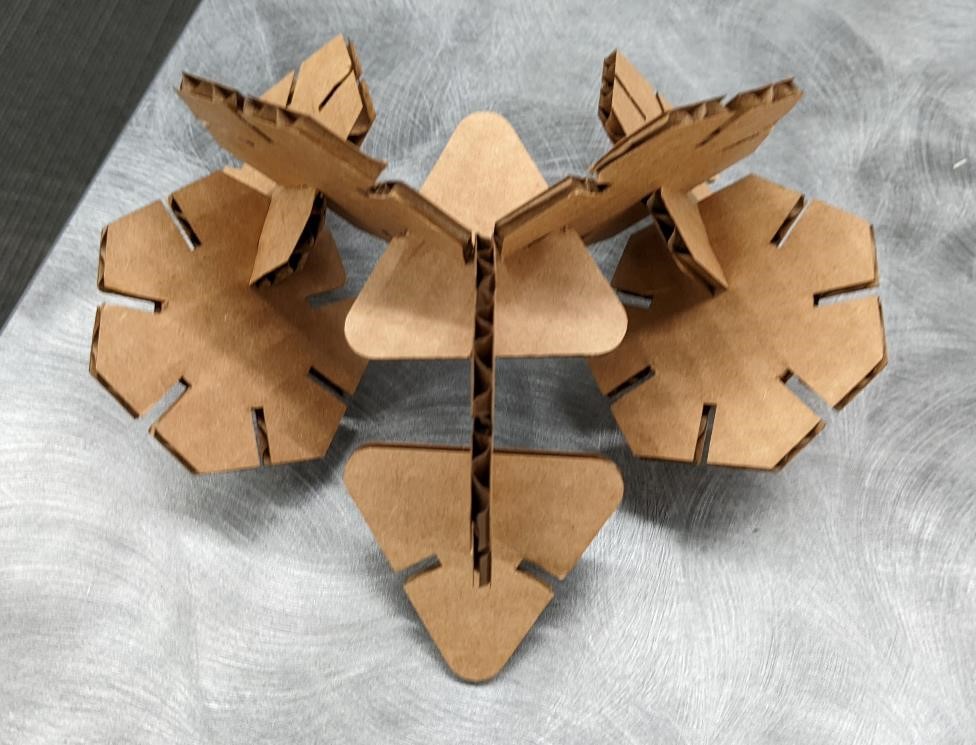
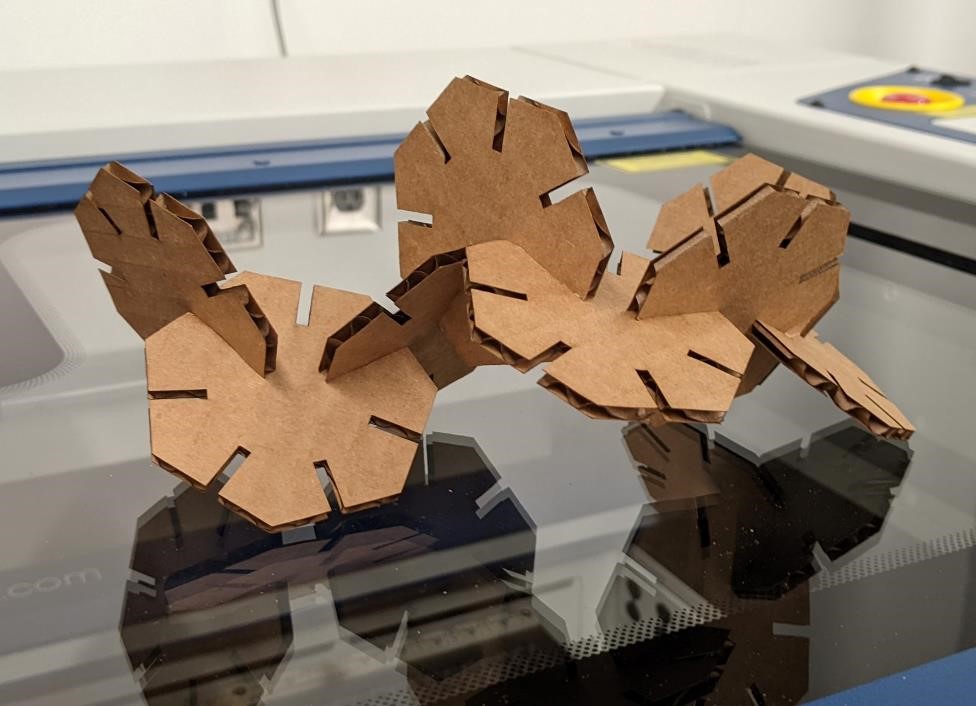
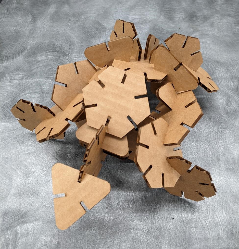
Final parts:
It’s useless, but it fits together in multiple ways.
Group Project
This week’s group project was all about testing the laser cutters and find out which settings are best for different use cases.
You can find the group project for this week at the CPCC FabLab Site for Week 4.
I helped with setting up the laser cutter, creating some of the test patterns, making some cuts, and documentation.