7a. Group Project - Electronics Design
Week 6 - 3/2/22
This week, the group assignment consisted of using our lab’s electrical testing equipment to investigate our projects and microcontrollers.
This week was a bit of a struggle. CPCC was on spring break this week, and two of our electronics experts, Denny Leak and Adam Harris were on vacation. Jami Dale was also busy, leaving just Cori and Garrett to work with the electronics equipment. Probably the least experience of everyone in the group dealing in this area.
There were also some problems with finding the proper equipment and accessories, as even the lab assistants were on vacation this week.
That said, we did the best we could.
Which basically meant trying to touch expensive pieces of electronics test equipment to poorly built and poorly understood electrical circuits without setting the building on fire. This I can say, we were successful at. There were no electrical fires started by us this week.
Cori tried to stick a fork in an electrical socket, but Garrett stoped her just in the nick of time.
Garrett licked the two leads of a large, fully charged electrolytic capacitor. It tasted like strawberries. And burnt meat.
(that’s a joke kids, don’t do it.)
We were able to turn on the Oscilloscope, and properly pronounce Oscilloscope. Both wins in our book.
After finding a place to connect the ground wire to, and get the stupid alligator clip to stay on, we were able to probe the blink circuit.
One of the more difficult parts was trying to figure out which knobs of the Oscope to turn, and what each one did. While Garrett got a brief tour from Adam Harris, it turned out to be one of those “Sure, I understand all of this!” And then a few days, you later realize that a) You didn’t actually understand as much as you thought you did. b) What you did understand, you’ve promptly forgot because you didn’t take any notes. c) You have no idea what you’re doing.
That said, we did see the line of the oscilloscope jump when the LED turned on, and go back to 0 volts when it turned off.
(and it doesn’t like it when you touch 5v to ground.)
All in all, we didn’t quite know exactly what we were doing, and it was a late night.
Later on, we found a nice video on youtube provided by Sparkfun:
How to use an Oscilloscope https://www.youtube.com/watch?v=u4zyptPLlJI
Second Attempt!
We came back to this later with more guidance from Adam and to hunt down a problem with my board. We had been troubleshooting Cori’s new board; she couldn’t get my NeoPixel to light up, so we decided to check that everything was working.
We started with the oscilloscope. An Siglent SDS2102 (manual can be found here: https://siglentna.com/USA_website_2014/Documents/UserManual/SDS2000_UserManual_UM01020-E03A.pdf)
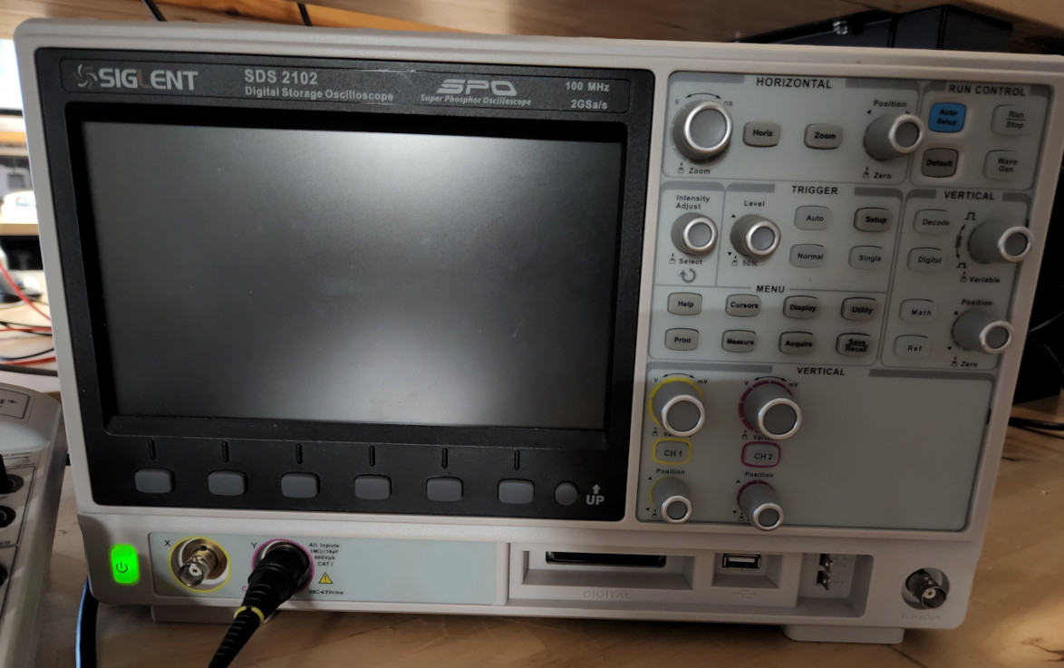
The oscilloscope has two channels, which are labeled with both a letter and a color. We were using the Y, or pink, channel, so we turned off the X, or yellow channels. This also let us check that the correct channel was on and displaying.
There are two buttons that are useful for getting quick measurements, Trigger AUTO, which determines when it will capture data, and Auto Setup, which automatically detects the range of our data. The display shows voltage and frequency and can be adjusted with knobs. We changed the divisions to 2v per division, and the dotted line between the solid lines marks the halfway point. The bright line in the middle of the screen is our zero.
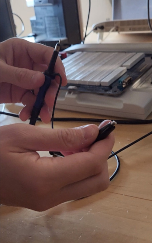
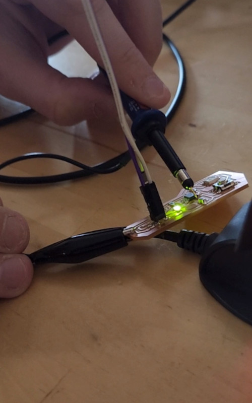
Last, we need our probes. The ground wire is an alligator clip that attaches to either the ground wire, or in our case, the ground trace on the board. The tip of the second probe is interchangeable. The cap has a little grabber that can grab and hold onto a wire, but since we’re testing leads, we removed the cap, revealing a small probe that can be used for more precise measurements.
Ready to go!
Our first attempt to get a reading didn’t quite go as planned. The signal was really dirty and strange.
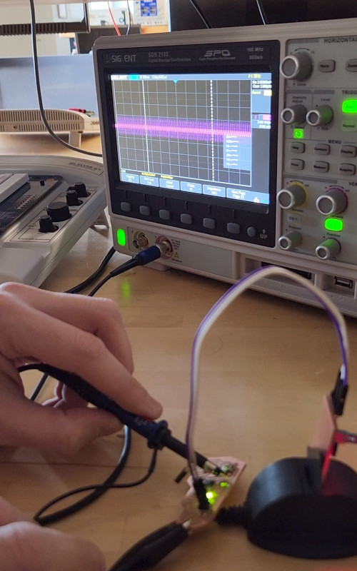
We figured this was due to a bad connection to ground.
We adjusted the knobs that controlled the timing, but the signal didn’t look much better. We also checked that we were measuring DC vs AC. We were still getting a bad reading, so we recalibrated the probes by using the prongs on the front of the oscilloscope. Still no luck.
Old School Cool
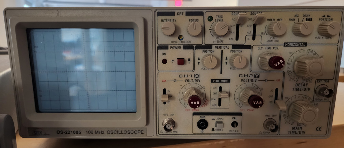
Since we weren’t having much luck with the newer model, we switched to the older oscilloscope to try again. This one works the same way as the first model, but required a couple more adjustments before starting.
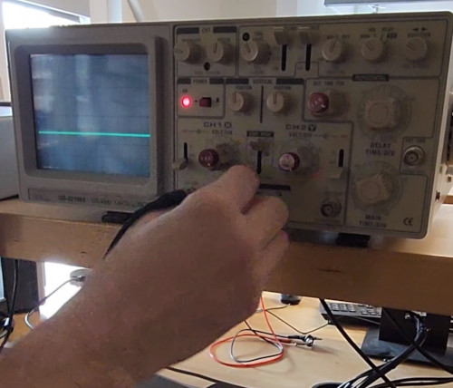
Again, we made sure we were using the correct channel that matched where we were plugged in, then we moved the reading line to the center of the screen. We adjusted the knob to 2v per division, but again, we didn’t have much luck.
Time for the Multimeter
We used an older HP 34401. The manual can be found here: https://engineering.purdue.edu/~aae520/hp34401manual.pdf
Here’s a video on the basics of learning to use a multimeter, again from Sparkfun: https://www.youtube.com/watch?v=SLkPtmnglOI
We switched yet again, this time to the multimeter. At this point, we wanted to check that the board was actually receiving 5v at all. On the one hand, we knew it was because it was able to be programmed. On the other, we weren’t having much luck beyond the program confirming that it was written.
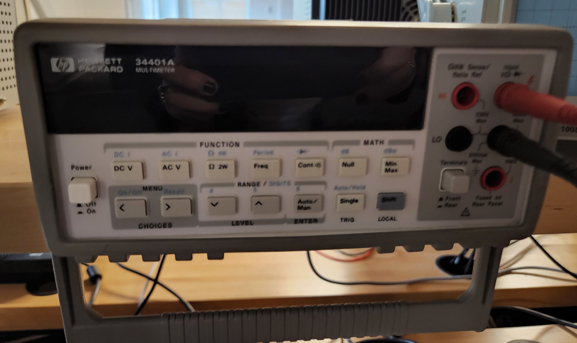
When we turned on the multimeter, it defaulted to volts. If we wanted to measure resistance, then we could press the OHM button. If we wanted to check the current, we would press shift and DCI. But with this machine, there are different connections for different measurements, so if we changed to check current, we would have to plug into the current plug. Ground always uses the same socket, but there are different sockets for voltage, ohms, current, and for checking diodes.
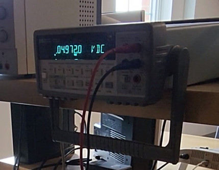
We checked it and we’re able to confirm that the board was getting 5v just fine, so the issue was elsewhere.
And we learned a bit about dirty vs clean power and how to get clean power: https://www.allaboutcircuits.com/technical-articles/clean-power-for-every-ic-part-1-understanding-bypass-capacitors/
Back to Old School
We decided to go back to the oscilloscope and instead of clipping the ground, we would just touch the trace with the clip. That way we knew for sure that we were getting a solid connection. Once we got that down, it was only a matter of trial and error, and lots of adjusting of the dials to see any movement.
Since we were testing for power, we were looking for the line to jump from the center up to the 5v division. Luckily, we were able to get a signal. At this point, Cori went back and tried programming the board again, but she didn’t have any luck, so we decided to try a different method.
This time, we decided to check the chip. If we programmed the chip correctly, then the specific pin should be sending a signal that we can then detect. The line on the screen should toggle up high and low, showing the program telling the LED to turn on and off.
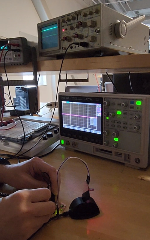
It worked! We were able to see the signal moving up and down on the screen, which means there wasn’t anything wrong with the board itself, and that Cori needed to step up her programming game.
And now that we know some things…
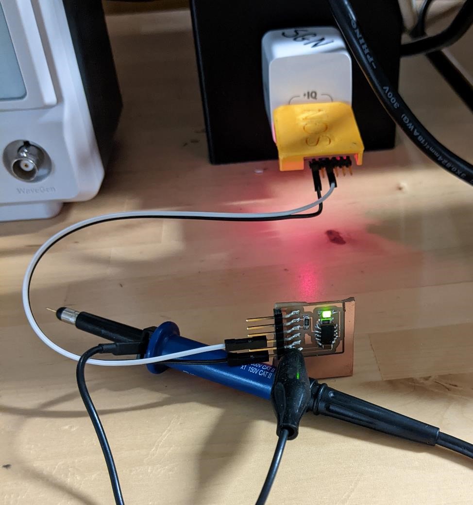
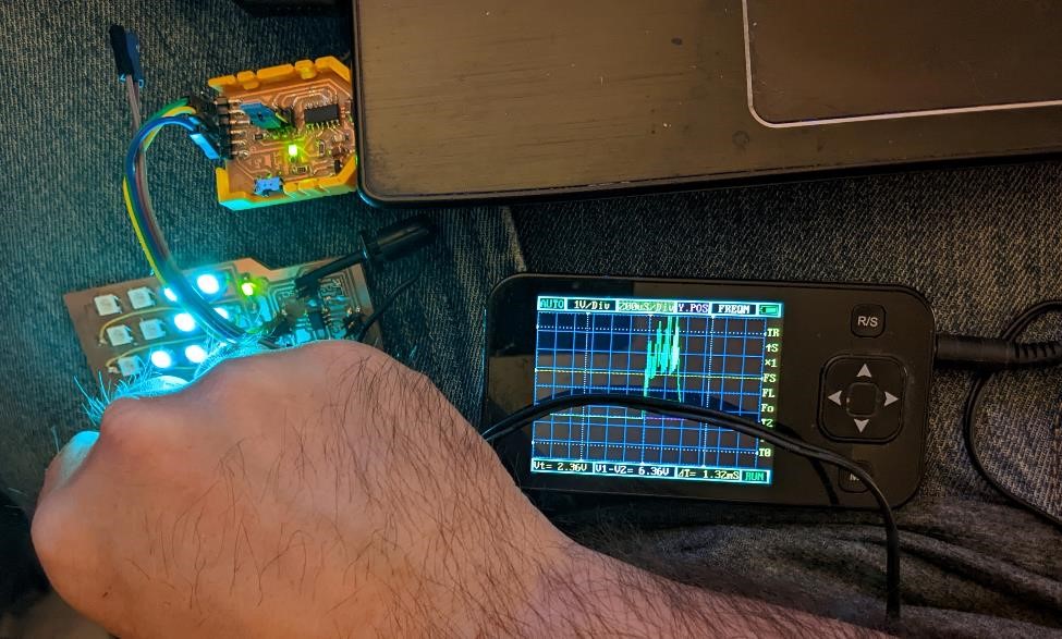
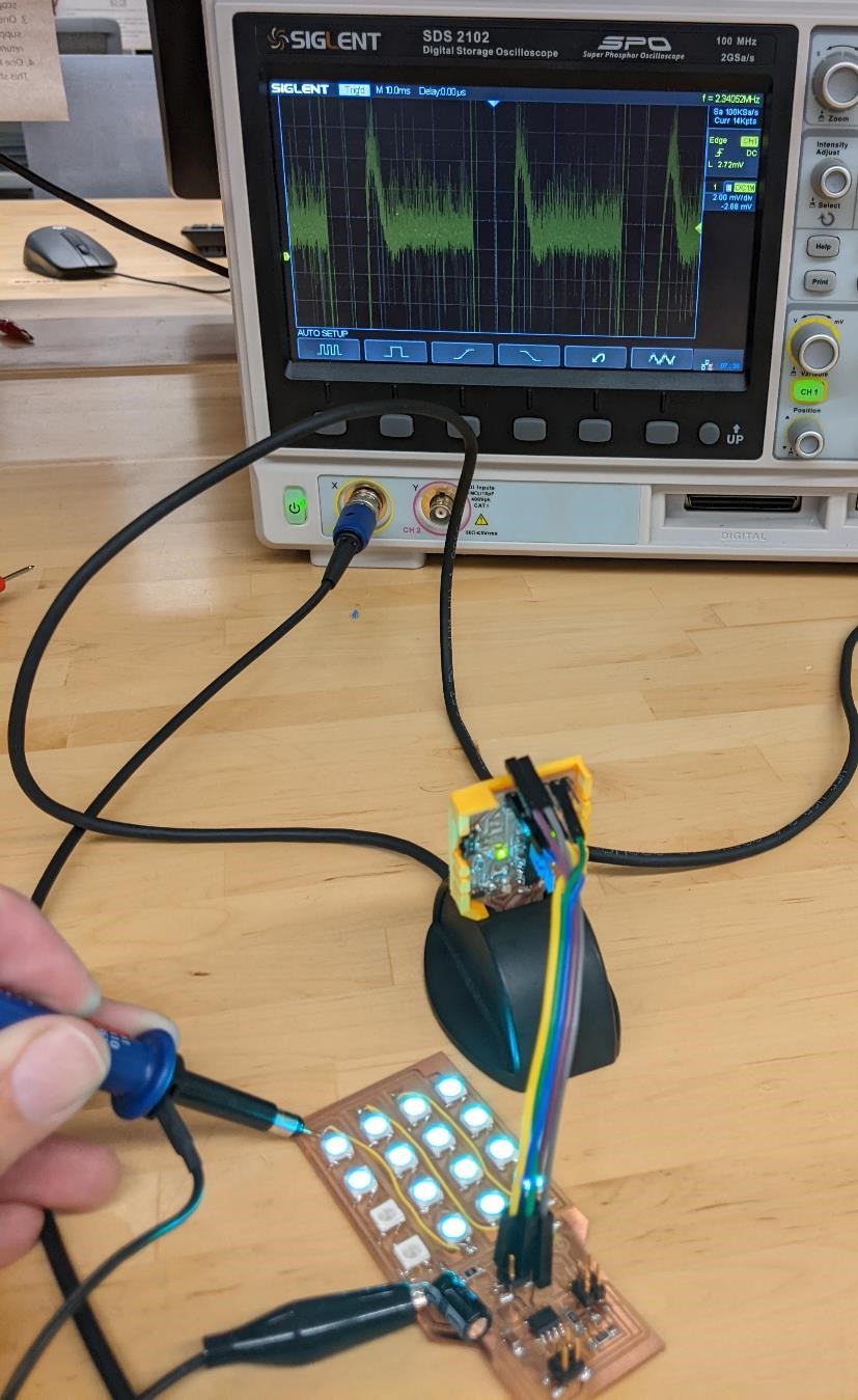
Garrett had an older, tiny, DSO at home with him and he tried it out with his Neopixel board.
We learned some interesting things about Neopixels from trying them out with the O-scope.
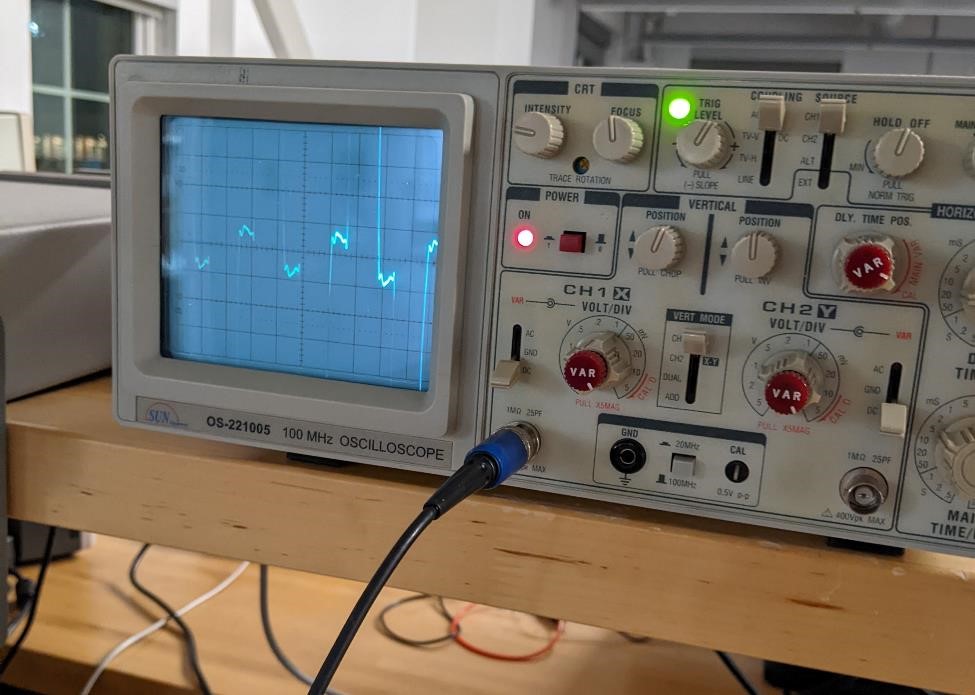
What we observed on the first Neopixel’s data line was a large pulses (of what must have been serial data?). But as we went down and tested each neopixel, the pulse got shorter and shorter. And finally at the last Neopixel, there was no more pulse.
We found this interesting, as we theorized that it must be a serial data, and that the Neopixel’s must be somehow smart enough to only send the data needed for the neopixel’s after it, and not the entire data packet. Again, these are all assumptions, and we understand the limits of our knowledge in this area. But at the very least, it was a cool little thing to notice.
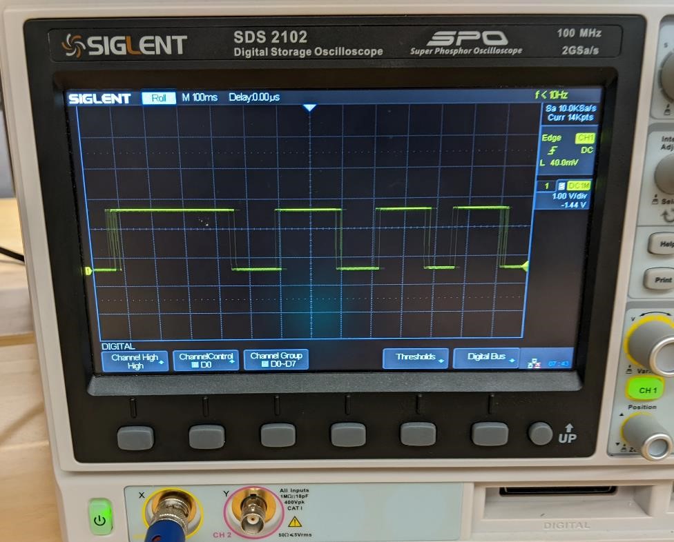
We did try to find the same data using a real O-scope later on, and noticed the same pattern, though it was bit more difficult to see.
And finally, here you can see the voltage (as in this case, the O-Scope was running very slowly, and the probes were being touched and removed from the 5 volt line.)
It seemed that the power signal around the capacitor was very clean, but was less “clean” around the Neopixels.
What we learned:
There’s not much going on in a very simple attiny412 blink circuit.
It’s helpful to have long USB extension cords.
We should have found something like an arduino to program and use, but we didn’t know what we’re doing, so it’s doubtful how much this would have helped us.
We have a lot more to learn about basic electronics.
Have someone who know what they’re doing help you out.