Work log - Week 18 - May 25, 2022
Wednesday 5/25
Attended class, which focused on intellectual property.
Neil did a good job of covering this.
Didn’t have too many great links to share this week.
Somehow we got on the machinability of Brass. Neil thinks it’s difficult. It’s not.
https://www.copper.org/applications/rodbar/pdf/a7050-brass-vs-steel.pdf
Thursday 5/26
Worked on final project, banged my head against the wall trying to get the satshakit https://github.com/satshakit/satshakit working. I had very little success.
Part of the problem was that the chip is actually an Atmel 328, NOT a 328P. Minor thing, but it makes a difference when burning the bootloader.
Please refer to this link about burning a bootloader by using an Arduino Bootloader: https://learn.sparkfun.com/tutorials/installing-an-arduino-bootloader/all
A couple of things to note.
- You need to burn the ‘ArduinoISP’ code to your arduino you’ll be using to program. It’s found under examples.
- If you are using the 328 chip instead of the 328P, you’ll need to change the signature of the chip for avrdude. See: https://fabacademy.org/archives/2013/students/anderson.douglas/atmega328.html
Also found this helpful: https://docs.arduino.cc/built-in-examples/arduino-isp/ArduinoToBreadboard
Friday 5/27
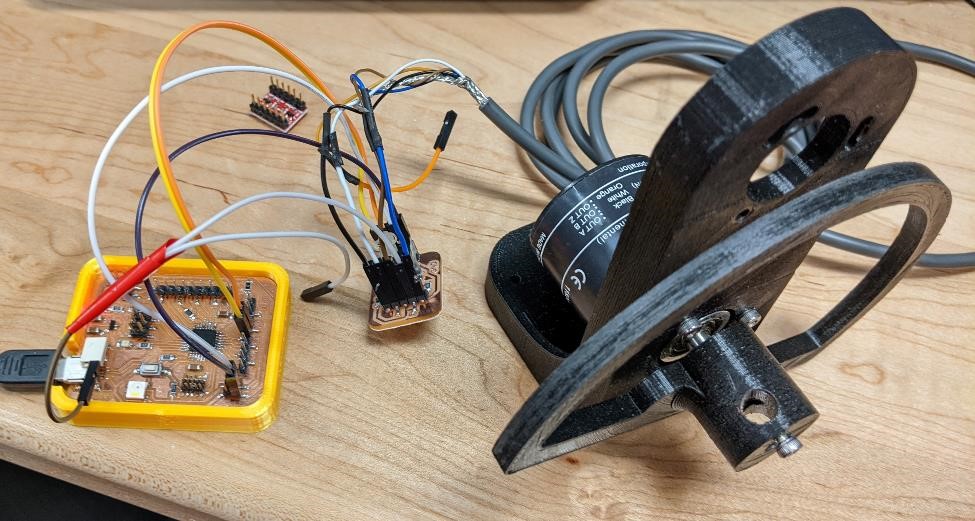
Quadrature Encoder Success
FINALLY.
Manged to get one of my own boards to read the quadrature encoders. This was a major pain in the butt, and kept me from really moving forward with my final project. Thank goodness I finally got something to work.
One of the many frustrating things about this was that I could get this to work on any Arduino UNO without any problems whatsoever. But I couldn’t get it to work on a single board that I designed (ATtiny412, SAMD11, SAMD21)
Finally I tried my newer SAMD21 board. After literally hours of almost banging my head against the wall, I finally was able to get it working. I was just about to give up and leave for the day when I thought about just changing the pins.
After googling “Why don’t my SAMD21 interrupts not work?” (or something like that) I had an epiphany and looked into the Mattairtech SAMD21 board manual Rev A: https://usermanual.wiki/Pdf/MTD21EUserGuide.493056156/view and Rev B https://www.mattairtech.com/docs/MT-D21E/MT-D21E_revB_User_Guide.pdf of who’s arduino bootloader/firmware I’m running and voila, right there in black and white:
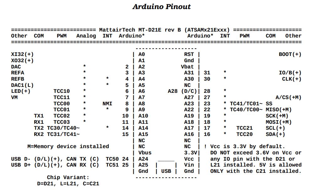
Int Pins and my notes, only on: 4, 5, 8 (NMI), 9, 14, 16, 17, 18, 19, 23 (led), 27 (neopixel), 28 (the one pin I don’t have connected to anything), 30 (used for JTAG), 31 (used for JTAG)
He doesn’t have PA02 or PA03 set up as interrupts!!!! ARGHHH
In fact, he doesn’t have a lot of the pins set up as interrupts (SAMD21 provides a lot of interrupts). Which is disappointing, to say the least. If I have the inclination (I don’t) or need (I do) I’ll have to go and see if I can change this at a later date.
Once I switched to Pins PA04 and PA05, everything started to work. This was a painful painful lesson to learn. I should have known. It’s always the pins.
And that was the dumbest part for this whole thing, it was just the wrong pins. I had been using Pins PA02 and PA03 to read the encoder signals. I couldn’t get them to trigger the interrupts, but I at least managed to get them to poll the signals, which told me this was a problem with the interrupt, not the encoder or pins themselves.
Encoder Program for SAMD21 sgn board.
This is the program I finally had success with. It comes from comments on this link: https://forum.arduino.cc/t/rotary-encoder-using-interrupts/469066/10
But before getting there, I tried a number of different encoder libraries and programs. There’s no telling how many would have worked if I had simply changed the pinout. Probably most of them.
And for the PIND line below, see this: https://arduino.stackexchange.com/questions/5308/what-is-this-pind-command I could not get this to work in the few minutes I tried with the SAMD21 board.
// https://forum.arduino.cc/t/rotary-encoder-using-interrupts/469066/10

#include "Arduino.h"

const byte encoderPinA = 4;  //outputA digital pin4
const byte encoderPinB = 5;  //outoutB digital pin5
volatile int count = 0;
int protectedCount = 0;
int previousCount = 0;
int led = 23;  // normal led pin samd21 sgn board

// #define readA bitRead(PIND,2) // faster than digitalRead() For UNO
// #define readB bitRead(PIND,3) // faster than digitalRead()

#define readA digitalRead(encoderPinA)
#define readB digitalRead(encoderPinB)

void setup() {
  pinMode(led, OUTPUT);
  SerialUSB.begin(0);

  pinMode(encoderPinA, INPUT);
  pinMode(encoderPinB, INPUT);

  attachInterrupt(digitalPinToInterrupt(encoderPinA), isrA, CHANGE);
  attachInterrupt(digitalPinToInterrupt(encoderPinB), isrB, CHANGE);
}

void loop() {
  noInterrupts();
  protectedCount = count;
  interrupts();
  // SerialUSB.println("working");  //test
  if(protectedCount != previousCount) {
    SerialUSB.println(protectedCount);
    digitalWrite(led, HIGH);
  }
  previousCount = protectedCount;
  digitalWrite(led, LOW);
}

void isrA() {
  if(readB != readA) {
    count ++;
  } else {
    count --;
  }
}
void isrB() {
  if (readA == readB) {

 count ++;
  } else {
    count --;
  }
}
Logic Level Converters
First, I used a logic level converter instead of my DIY pullup and current limiting resistor board. (see week 16 for that board.)
It was an older Sparkfun logic level converter board, BOB-08745, and it apparently is not the best, but it worked fine for my purposes. This link here was helpful when I looked into my own LLC’s https://learn.sparkfun.com/tutorials/retired---using-the-logic-level-converter?_ga=2.71190675.2084743952.1653665752-147108062.1653665752 I put a multimeter on it, and it was doing exactly what it was supposed too. One hurdle leaped.
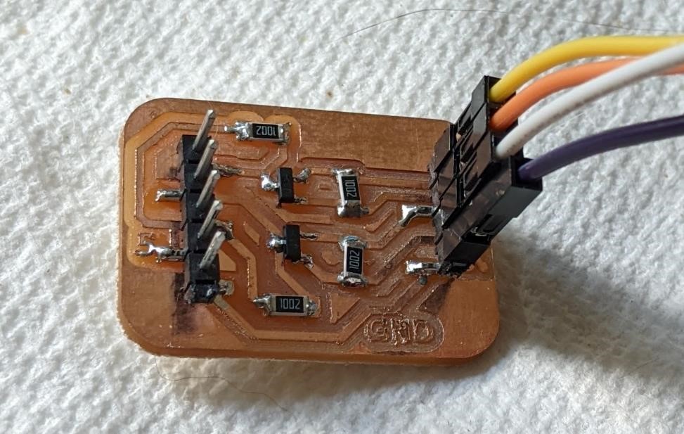
After this, I was able to read the encoder successfully. Next I wanted to create my own Logic Level converter, especially as I knew the Sparkfun ones that I had were adequite, but I didn’t quite trust them. I also felt like it’d be quick and easy to do, and for something like this, it’d help me prepare for creating a specific board to do all of these features in one, instead of a dev board.
I based my design off of this product from Sparkfun, a newer logic level converter with 4 channels
One of the great things about Sparkfun, and it was Adam Harris who told me this, is that they provide schematics for their own board designs. So I found their schematic, and essentially duplicated it for my board. It’s using a BSS138 transistor with 2 10k resistors for each channel. A very basic and simple design.
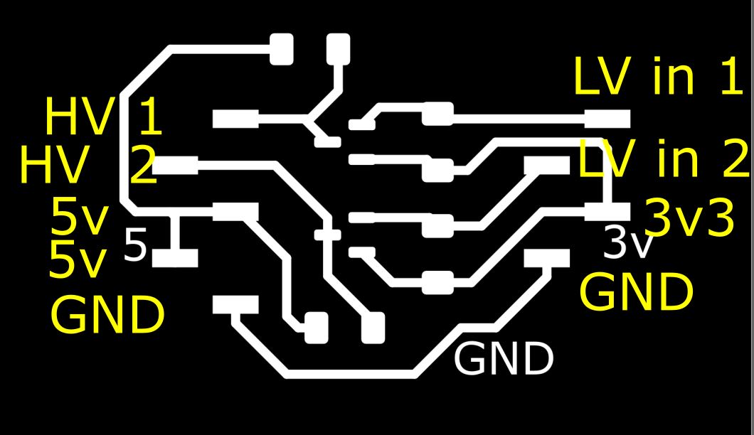
I created a two channel design (I need 2 channels for each encoder, and single sided boards limit things a bit.)
I also added an extra pin that splits the 5v line to the logic level converter (they need to be powered by both the 5v and 3.3v power supplies), so I can attach a 5v in line, that will also go to the encoder to power it.
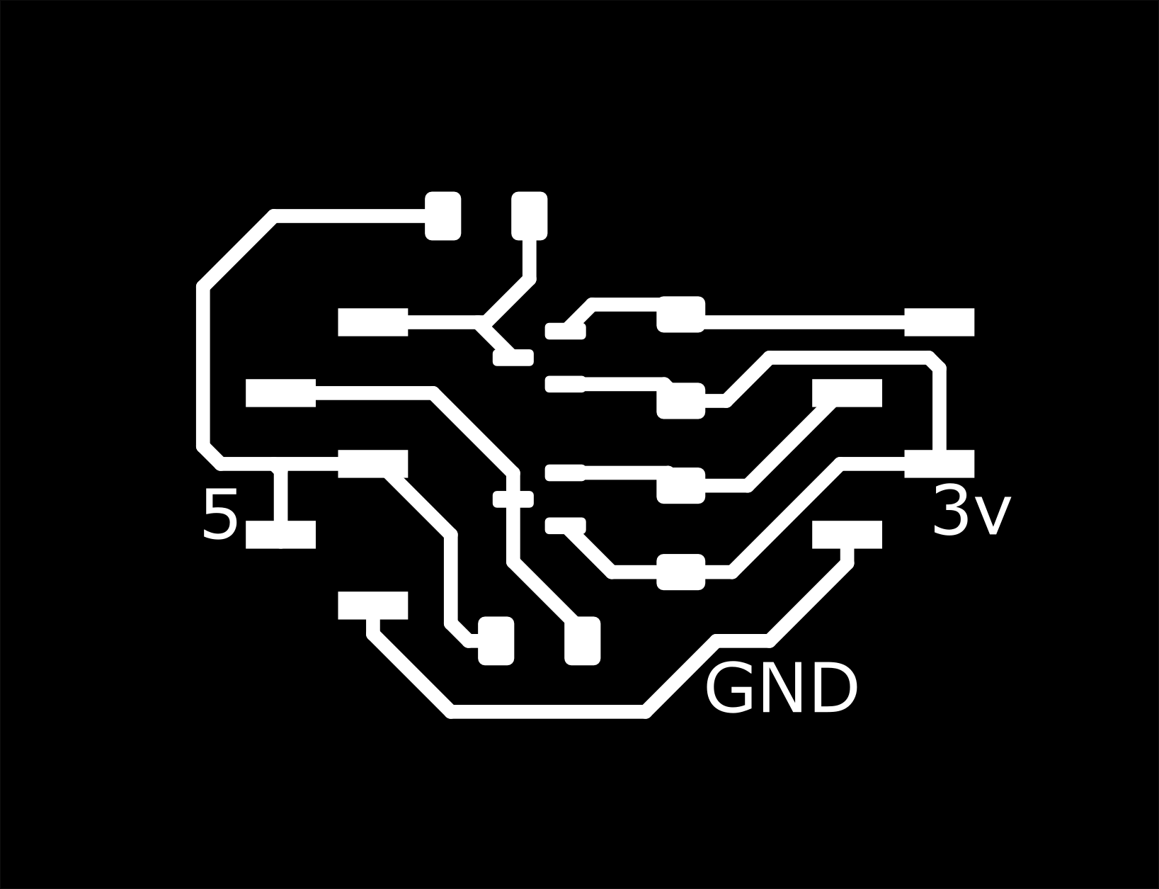

Again, this board simply consists of 2 BSS138 SOT-23 transistors and 4 10k 1206 resistors
Here’s the hookups for the board. I have the inputs/outputs at the top, and then the 5v/3.3v under the those. There are two 5v power inputs on the left side, this is because I need to provide 5v power to the rotary encoder as well as the board, so I’m just using this as a 5v power distribution board. And finally, the last pin for these is the common ground.
And here’s the video.
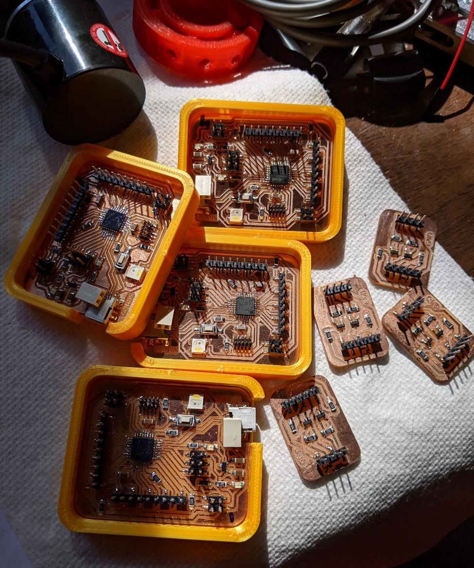
Then I ran production
Made a mess of samd21 and llc boards:
Next Up
Now I need to see if I can hook up two encoders to one board.
I need to see how to get the data out to a computer (i2c again? serial over usb?)
And start programming to get useful data out.
And build it all. And document it all. That’s all.
Saturday 5/29
Kept working with encoders, worked a lot on physical/mechanical design, and improved a lot of the design aspects. Still have a lot to do.
Managed to print two of the exact same part, even though I knew it was a bad part. Because I’m just stupid like that sometimes. A waste of time and filament. But the third part was correct, and it was a good part.
Sunday 5/30
Continued working on physical design.
Printed out a number of test pieces, both as literal test pieces, as well as fitment tests.
Managed to get the SAMD11 board I designed to work with the encoders as well. This entire time, it was bad code and the lack of logic level converters. I wish I had known this much earlier. I would have been much further along with this project.
I was able to get the SAMD11 to read two encoders at the same time using interrupts. While I’m still working on testing, it appears that it doesn’t drop any data, at least on first glance.
Unfortunately, the problem the SAMD11 had from the very beginning is still an issue, lack of memory.
I even came across a very strange issue with the SAMD11.
I made some code that just changed the brightness of the neopixel based on the position of the encoder for testing purposes. Fairly simple, and when using one encoder, it works. However, as soon as I add a second encoder, it will not upload the code, and the Arduino IDE stops seeing the actual COM port and device identification.
It will compile the code, and tell me that it will fit, however, as soon as I upload, it fails during the upload, and the SAMD11 com port disappears. It will pop up as a different COM port (but it doesn’t recognize the Device ID) and I upload a good program, it’ll come back, and the original COM port will again be recognized and the signature of the device is now displayed. It’s an odd bug, but I’m convinced it’s all due to lack of memory. Okay SAMD11.
But it is good that I can at least get data off of one encoder and do something extra like use a neopixel. The point from the beginning was to use a smaller microcontroller to get data from the encoders and pass it along for further processing down the line. But not being able to use the attiny412 or the SAMD11 changed this and I switched to the SAMD21. I’ll probably stick with the SAMD21, but at least this gives me another option.
Anyways, here’s the code fo the SAMD11 and two rotary encoders. It should work with a SAMD21 as well.
// https://forum.arduino.cc/t/rotary-encoder-using-interrupts/469066/10

#include "Arduino.h"

const byte encoderPinA = 8;  //outputA digital pin4
const byte encoderPinB = 9;  //outoutB digital pin5
const byte encoderPinC = 30;  //outputA digital pin4
const byte encoderPinD = 31;  //outoutB digital pin5

volatile int count = 0;
int protectedCount = 0;
int previousCount = 0;

volatile int count2 = 0;
int protectedCount2 = 0;
int previousCount2 = 0;

#define readA digitalRead(encoderPinA)
#define readB digitalRead(encoderPinB)
#define readC digitalRead(encoderPinC)
#define readD digitalRead(encoderPinD)

void setup() {

  SerialUSB.begin(0);

  pinMode(encoderPinA, INPUT);
  pinMode(encoderPinB, INPUT);
  pinMode(encoderPinC, INPUT);
  pinMode(encoderPinD, INPUT);

  attachInterrupt(digitalPinToInterrupt(encoderPinA), isrA, CHANGE);
  attachInterrupt(digitalPinToInterrupt(encoderPinB), isrB, CHANGE);
  attachInterrupt(digitalPinToInterrupt(encoderPinC), isrC, CHANGE);
  attachInterrupt(digitalPinToInterrupt(encoderPinD), isrD, CHANGE);
}

void loop() {

  noInterrupts();

  protectedCount = count;
  protectedCount2 = count2;

  interrupts();

  if(protectedCount != previousCount || protectedCount2 != previousCount2) {
    SerialUSB.print(protectedCount);
    SerialUSB.print(", ");
    SerialUSB.println(protectedCount2);
    delay(100);  //this isn't to overflow Processing's serial buffer
  }
  previousCount = protectedCount;
  previousCount2 = protectedCount2;

}

void isrA() {
  if(readB != readA) {
    count ++;
  } else {
    count --;
  }
}
void isrB() {
  if (readA == readB) {

 count ++;
  } else {
    count --;
  }
}

void isrC() {
  if(readD != readC) {
    count2 ++;
  } else {
    count2 --;
  }
}
void isrD() {
  if (readC == readD) {

 count2 ++;
  } else {
    count2 --;
  }
}
Basic Serial Read Processing Code
Here’s the very basic “get data from encoders into processing sketch. Very simple, very basic. But it’s the first test piece.
It’s modified from the Processing serial read example code.
Also, it’ll break with a null pointer exception. see the below code for an updated fix for the serial read section (just an if (val != null) { …)
/**
 * Simple Read
 *
 * Read data from the serial port and change the color of a rectangle
 * when a switch connected to a Wiring or Arduino board is pressed and released.
 * This example works with the Wiring / Arduino program that follows below.
 */


import processing.serial.*;

Serial myPort;  // Create object from Serial class
String val;      // Data received from the serial port

int[] encoders;
String[] rawEncoders;


void setup()
{
  size(640, 360);
  // I know that the first port in the serial list on my mac
  // is always my  FTDI adaptor, so I open Serial.list()[0].
  // On Windows machines, this generally opens COM1.
  // Open whatever port is the one you're using.
  println(Serial.list());
  String portName = Serial.list()[0];
  myPort = new Serial(this, portName, 250000);
}

void draw()
{

  if ( myPort.available() > 0) {  // If data is available,
    val = myPort.readStringUntil('\n');         // read it and store it in val
    //println(val);  // print the value we're receiving from serial port

    rawEncoders = trim(splitTokens(val, ","));  //split on comma, remove whitespace

    //for (int i = 0; i < 2; i ++) {  //testing
    //  println(encoders[i]);
    //}

    println(rawEncoders[0]);
    println(rawEncoders[1]);
    }

  background(255);             // Set background to white

}
resources:
used the arduino map function: https://www.arduino.cc/reference/en/language/functions/math/map/
Serial and Arduino/Processing: https://itp.nyu.edu/physcomp/labs/labs-serial-communication/serial-output-from-an-arduino/
Why is Processing so slow with my serial data? It’s sending it too fast? https://forum.processing.org/one/topic/ridiculously-long-delay-on-processing-and-arduino-serial-communication.html
Old School LadyAda: https://www.ladyada.net/learn/arduino/lesson4.html
More serial data and arduino: https://forum.arduino.cc/t/serial-input-basics/278284
Direction of rotary encoder, has info on multiple encoders in lower section: https://arduino.stackexchange.com/questions/32572/how-to-detect-the-direction-of-a-rotary-encoder/32582#32582
Monday 5/30
bad mistakes, and I’ve made a few
I did something very dumb.
I walked up to the computer, opened up Processing and just started programming. I’ve had about zero experience with Processing.
I should have stuck with Python, since I’ve had much more experience with it.
However, that wasn’t the mistake.
The mistake was that I didn’t sit down and plan out the program and what it would do before I started programming.
I was so intent on trying to get the data to be read in from the board, that I didn’t really think past this part.
That was dumb.
So now I’m going to plan out what my program is going to do, and intersperse that with some psuedo-code.
Progam Planning
The board will continuously count encoder positions using interrupts. When it senses a button press it will then take it’s current positions and send this data over Serial USB to the computer.
At the computer, Processing will be waiting for the information from the board.
Upon receiving data, it will break the different encoder positions into discrete values (since they come in as one long string, it’s important to break them apart.) and then take this information and add it into an array for each encoder.
Once that data is stored in an array, it will have to be calculated to get the actual position of this arms.
We need the arm lengths, let’s say for the sake of argument, they’re 200mm in length each.
This is all angle data, and currently it consists of 1000ppr rotary encoders, set to collect 4000cpr. This will have to be turned into an angle position. (and 360 / 4000 = 0.09) But I might stick with using Radians, because Processing uses Radians.
Next, the angle position will have to be added to the length of each arm and then converted into an absolute position based on arm length and rotary positions. This is going to invovle a lot of trigonometry.
But the really hard part is to make this into a 3d application. That seems too overwhelming for now, so I’m going to focus on 2d at the moment. Once I’ve got that down, I’ll add the 3rd dimension.
Challenges and Issues
Since these are incremental rotary encoders and not absolute, they’ll need to be placed in a starting position for calibration before use. I’ll have to come up with a solution for this. Probably have the first button press “calibrate” everything to zero, and move on from there.
The boards are spitting out data over USB serial, and they’re doing it really quickly, possibly over 500,000 baud. However, processing can’t keep up with this amount of data and quickly falls far behind. I’ve tried a few different things to allow Processing to handle the data, but nothing so far has been as successful in the way I would like. I believe I’ll simply add a delay to the arduino board code to help with this. Testing seems to show that I won’t drop any encoder data on the board due to the delay, so this may work.
I’ve also implemented a button to send data when the button’s pushed. But I really don’t like this, as I want to see a model of the arm constantly moving and only use the button to collect points, not just to only send the location at the time. It’d work, but it’s not really was I was hoping for.
I’m going to probably have to have multiple boards if I want 5 encoders total. This is going to make it challenging to get all this data in, and maintain it in a proper order.
And again, making this a 3d system. Yikes. I’ve had enough issues with 2 dimensional.
References and resources
Getting Angles from rotary encoders:
https://forum.arduino.cc/t/how-to-convert-the-rotary-encoder-output-to-angle-for-this-system/432336
Cool page on accuracy of rotary encoders: https://www.renishaw.com/en/the-accuracy-of-rotary-encoders--47130
And processing is really bad with reading serial data quickly: https://forum.processing.org/two/discussion/2454/serial-connection-to-arduino-throws-nullpointerexception-error-best-answer-gets-a-poem
Current Processing Code.
This is just a very bare bones, basic, 2d only, 2 encoder only system. But it’s helping me get my head wrapped around all the things going on.
I got much of this from this great video on forward kinematics from Coding Train: https://www.youtube.com/watch?v=xXjRlEr7AGk. Without this video I think I would have been completely lost.
This code is still very much a work in progress. (It’s bad.)
I also think that I’m only getting half the pulses I should be out of one encoder. I’ll have to check this out later. Could be wiring, or another interrupt issue.
/**
*
*   Serial Read of encoders and output of angles
*
*   S. Garrett Nelson May 2022
*
*  Code comes form a variety of places, serial read example from Processing
*  And Coding Train on Forward Kinematics: https://www.youtube.com/watch?v=xXjRlEr7AGk
*  And lots of help from: https://github.com/dzlonline/3D_digitizer2
*
**/

import processing.serial.*;


float ARM1 = 100;       // Arm Segment 1 length in mm
float ARM2 = 150;     // Arm Segment 2 length in mm

float STATES_PER_REV = 2000;  //Encoder half of number of counts per revolution. Why half?

Serial myPort;  // Create object from Serial class
String val;      // Data received from the serial port

String[] encoders;


int seg1Value = 0;  // direct value from encoders
int seg2Value = 0;

float seg0Angle = 90;
float seg1Angle = 0;  // angle in radians for segments?
float seg2Angle = 0;

Segment seg0;  // this is the base.
Segment seg1;  // prepare class Segment for use
Segment seg2;

void setup()
{
  size(640, 400);

  println("Serial Ports Available: ");
  println(Serial.list());
  String portName = Serial.list()[0];    // Open whatever port is the one you're using.
  myPort = new Serial(this, portName, 115200);  //baudrate don't work over USB serial

  seg0 = new Segment(250, height - 30, 50, radians(45));
  seg1 = new Segment(250, 200, ARM1, seg1Angle);  // x, y, length, angle
  seg2 = new Segment(seg1, ARM2, seg2Angle);
}

void draw()
{

  if ( myPort.available() > 0) {  // If data is available,
    val = myPort.readStringUntil('\n');         // read it and store it in val
    if(val != null) {  // because processing likes to shit itself with nulls when reading serial.
    //println(val);  // print the value we're receiving from serial port

    encoders = trim(splitTokens(val, ","));  //split on comma

    //for (int i = 0; i < 2; i ++) {  //testing
    //  println(encoders[i]);
    //}


    seg1Value = int(encoders[0]);
    seg2Value = int(encoders[1]);
    //println(seg1Value);  // for testing, as always.
    //println(seg2Value);


    seg1Angle = seg1Value * PI * 2 / (STATES_PER_REV * 2);
    seg2Angle = seg2Value * PI * 2 / STATES_PER_REV;
    println(seg1Angle);  // for testing
    println(seg2Angle);

    seg1 = new Segment(seg0, ARM1, seg1Angle);  // x, y, length, angle
    seg2 = new Segment(seg1, ARM2, seg2Angle);
    }


  background(55);             // Set background to grey

  seg0.update();
  seg0.show();
  seg1.update();
  //seg1.wiggle();  // this was for testing movement.
  seg1.show();
  seg2.update();
  //seg2.wiggle();
  seg2.show();

  }
}
And the “Segment” class code:
This is what does everything nicely, and so much thanks to Coding Train for this. Helped me just better understand programming in general, not just this project.
class Segment {
  PVector a;
  float len;
  float angle;
  float selfAngle;

  float xoff = random(1000);  // for wiggle

  Segment parent = null;
  Segment child = null;

  PVector b;

  Segment(Segment parent_, float len_, float angle_){
    parent = parent_;
    a = new PVector(parent.b.x, parent.b.y);
    len = len_;
    angle = angle_;
    selfAngle = angle;
    calculateB();
  }

  Segment(float x, float y, float len_, float angle_) {
    a = new PVector(x, y);
    len = len_;
    angle = angle_;
    calculateB();
    parent = null;
  }

  void wiggle() {  // used this for testing.
    selfAngle = map(noise(xoff),0,1,-2,1);
    xoff += 0.01;
    //selfAngle = selfAngle + 0.01;
  }

  void update() {
    angle = selfAngle;
    if (parent != null) {
      a = parent.b.copy();
      angle += parent.angle;
    }
    calculateB();
  }

  void calculateB() {
    float dx = len * cos(angle);
    float dy = len * sin(angle);
    b = new PVector(a.x+dx, a.y+dy);
  }

  void show() {
    stroke(255);
    strokeWeight(5);
    line(a.x, a.y, b.x, b.y);
  }
}