9. Embedded programming
Week 8 - 3/16/22
This week was about programming the electronics that we had created two weeks ago.
I had an attiny412 board with a neopixel (RGB) led and a button that I used for this week. You can read a bit more about this board and process in Unit 7., and I programmed it using the programmer we had created in Unit 5.
New Boards
Currently a Work in Progress, but I created a number of new boards for this week and the following weeks.
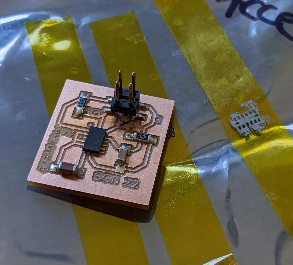
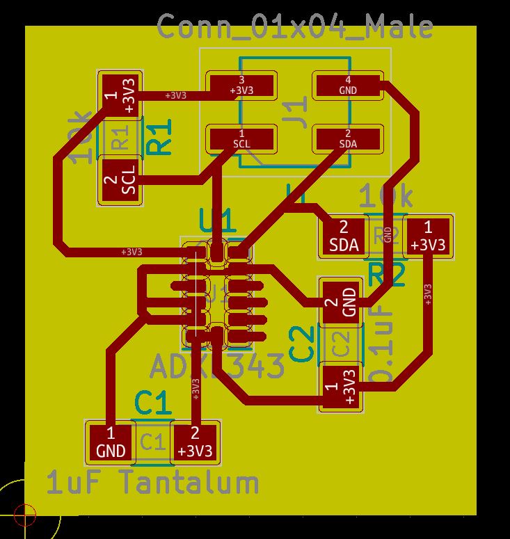
I want to experiment with an accelerometer, so I made a breakout board for an ADXL343, as well as a SAMD11C board with the ADXL343 on it. Who knows if either will work.
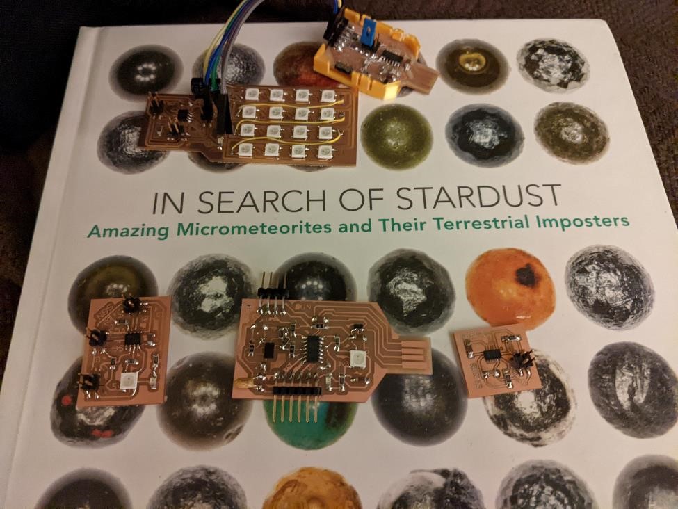
I also made another attiny based board with a neopixel, designed to communicate via i2c, and one larger board with the same design, but having 16 neopixels on it.
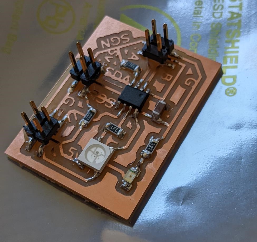
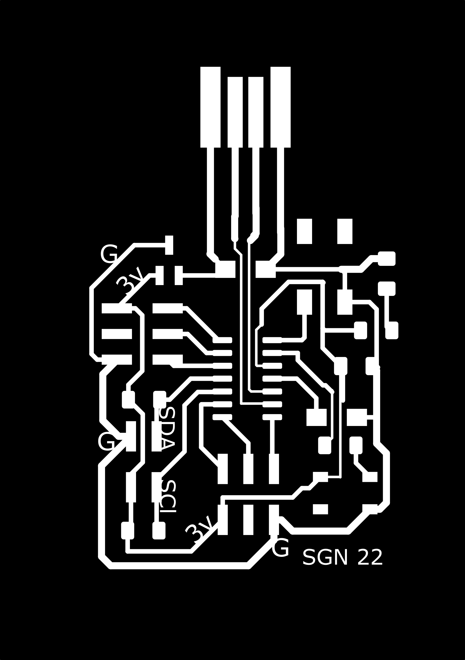
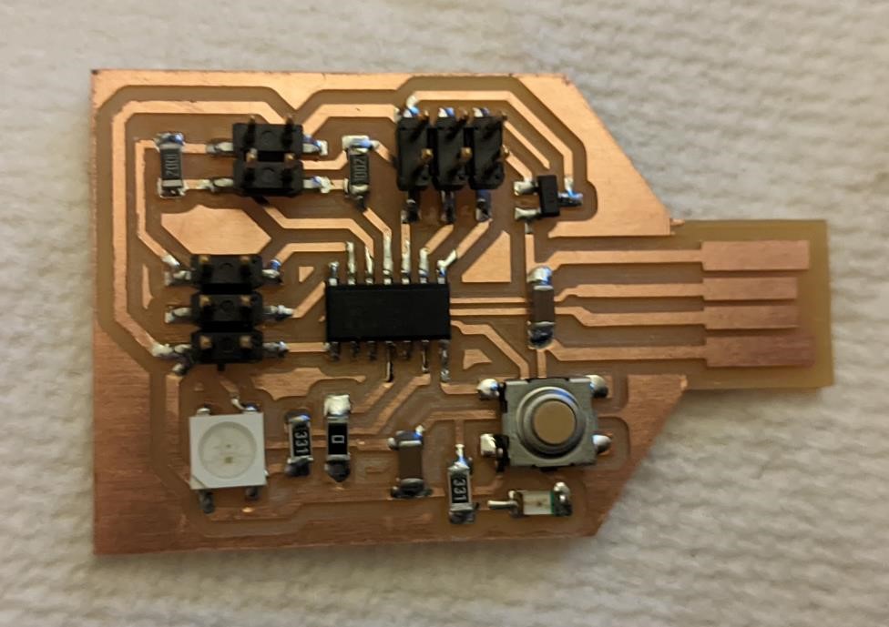
Attiny Neopixel board
Added i2c Pullup resistors; a 10k between SDA and 5v, and another 10k between SCL and 5v.
![]()
![]()
ADXL343 Breakout Board
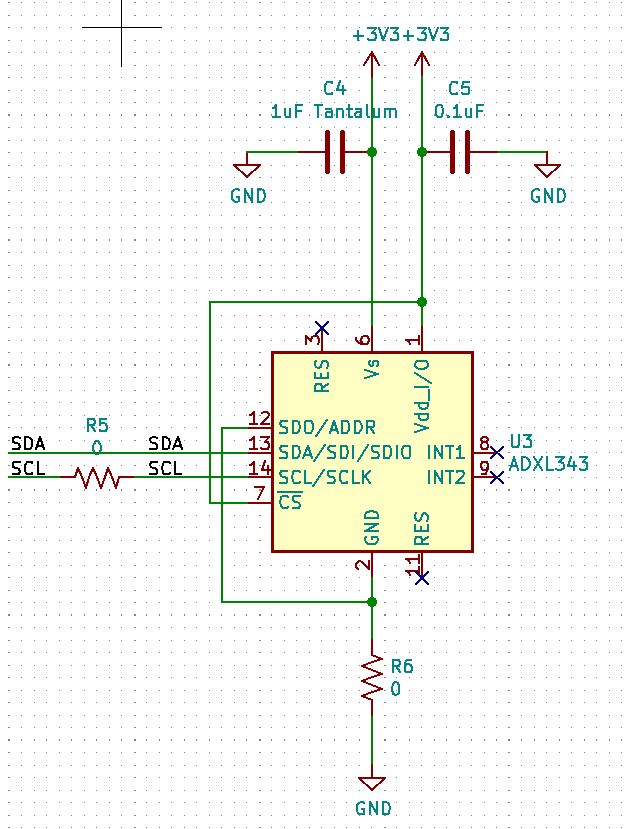
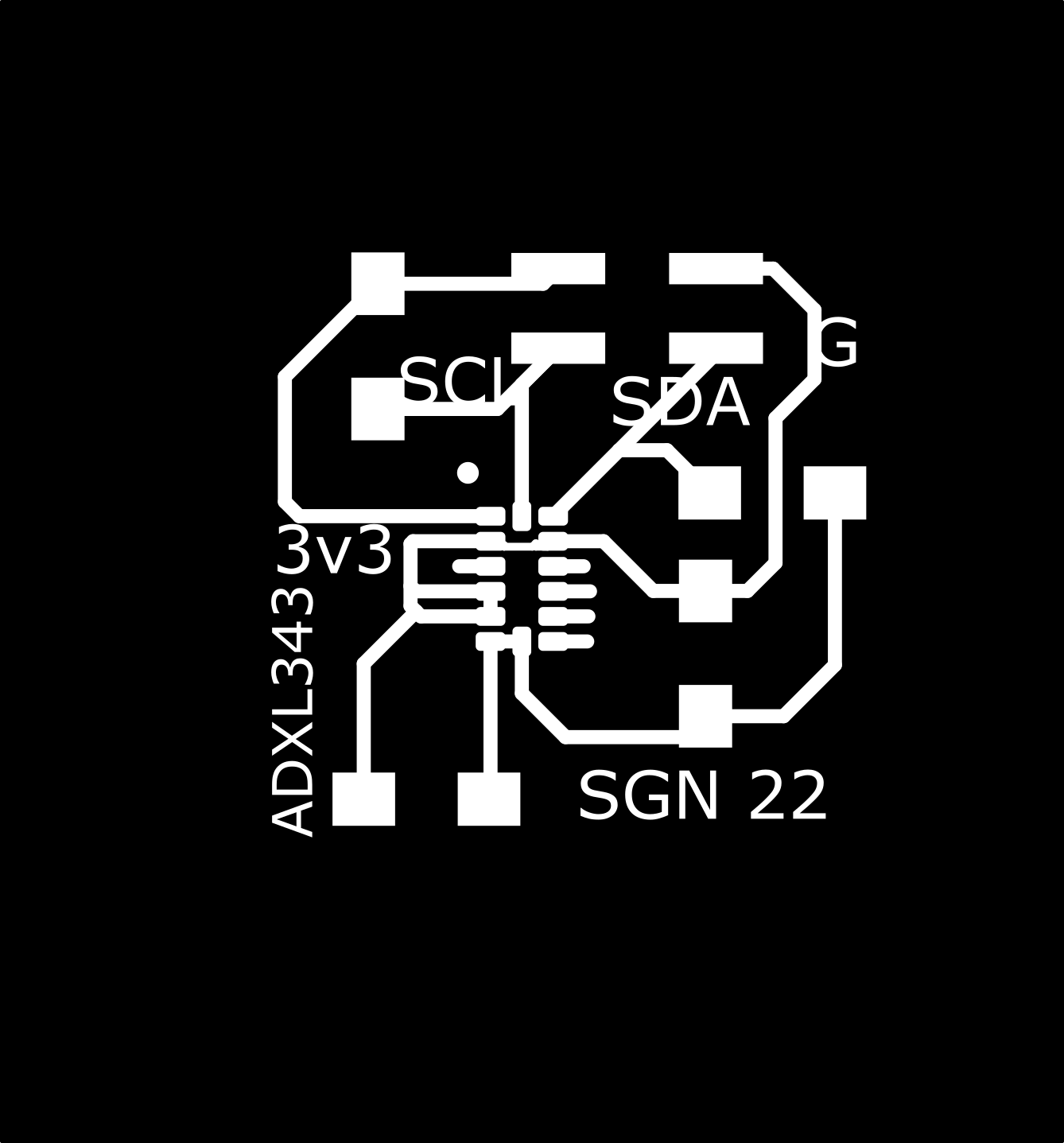

Notes from Adafruit on a similiar board: https://learn.adafruit.com/adafruit-adxl375
Big Neopixel Board
Note that for some reason, I mistakenly put a 1uF capacitor between the main 5v line and the 5v line connecting to the Neopixels. I’m sure I intended to add it between GND and 5v before the neopixels, but when I did this I was tired. I simply replaced the 1uF with a jumper (0 ohm resistor).
Also added was a 100uF electroylytic capacitor between 5v and GND right in front of the Neopixel voltage supply lines to act as a “storage” incase of extra demands for power.
I also added the jumper wires between each row of neopixels, connecting the DOUT of the last pixel per row to the DIN of the first pixel of the next row down. This worked well.
![]()
![]()
![]()
![]()
![]()
![]()
ATtiny412 boards.
I’ve been using attiny412’s for many of the small boards I’ve been making. As such I wanted to start with this “simpler” chip than the SAMD11C14.
You can find the basics of the Attiny412 on Microchip’s website here: https://www.microchip.com/en-us/product/ATTINY412
Attiny 412 App Notes
There are also a ton of very useful application notes on the main Attin412 page.
A few to make note of:
Getting started with GPIO: https://ww1.microchip.com/downloads/en/Appnotes/Getting-Started-with-GPIO-DS90003229B.pdf
Hardware design considerations: https://ww1.microchip.com/downloads/en/Appnotes/AN2519-AVR-Microcontroller-Hardware-Design-Considerations-00002519B.pdf
Interfacing Quadrature Encoder using CCL with TCA and TCB: https://ww1.microchip.com/downloads/en/Appnotes/Interf-Quad-Encoder-CCL-w-TCA-TCB-DS00002434C.pdf
Matrix keypads: https://ww1.microchip.com/downloads/en/Appnotes/00003407A.pdf
Attiny412 Data Sheet
The data sheet is here: https://ww1.microchip.com/downloads/en/DeviceDoc/ATtiny212-214-412-414-416-DataSheet-DS40002287A.pdf
It’s 585 pages, and in typical data sheet fashion, contains a large amount of the basic information about the chip, including capabilities, communications interfaces and both it’s electrical and physical specifications (Electrical Spcifications start on page 499, and go for about 50 pages. Physicla chip blueprints on page 557.).
Some of the information, such as it’s capabilities includes such informaiton about it’s “periphereals” and contains many more items than I would expect (and many items of which I have no clue what they do, such as Watchdog Timer (pp 170) Configurable Custom Logic and Event System (page 118).)
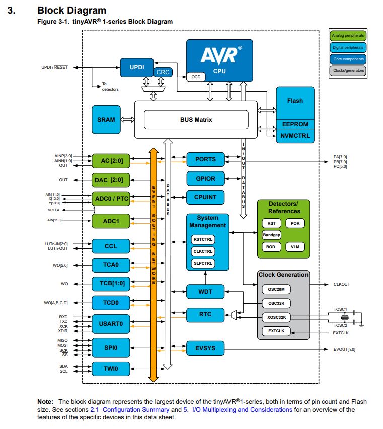
One thing that confused me when I was much younger was looking at the block diagrams of the chips, all the things that they’re capable of and then counting the number of pins.
The Attiny412 is an 8 pin package, and of course two of those pins are configured for input voltage and ground, leaving only 6 pins left. But if you look at the block diagram from the datasheet…
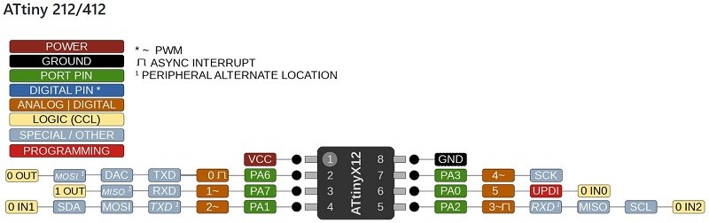
And the pinout from the datasheet…
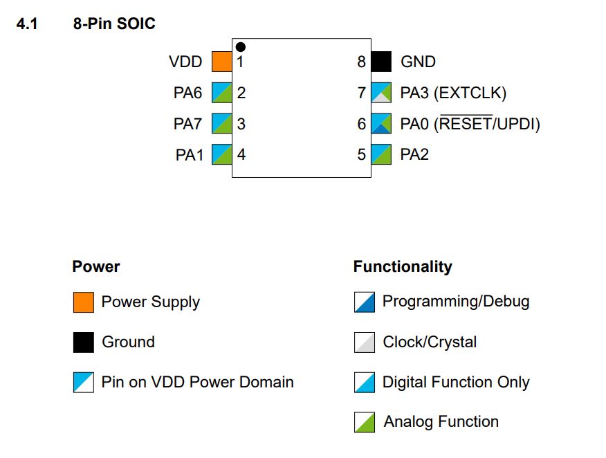
It makes it seem like it’s a hundred pins that can do just about anything. But of course, it’s up to the designer/engineer to choose which specific pins to use, and to make compromises (or choose a larger package with more physical pins) in order to have the ability to do all the things at once.
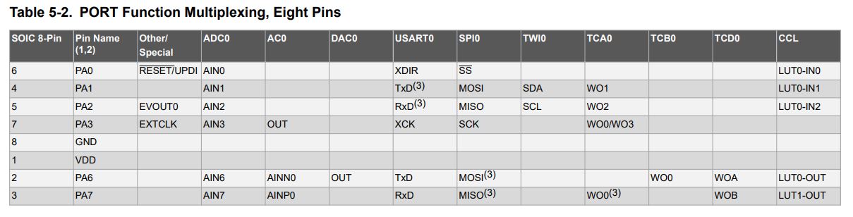
But you have multiplexing; the ability of each physical pin to take on different uses.
One thing I learned from the datasheet is that each chip has it’s own serial number, and a quick search came across this arduino forum post on how to read the serial number: https://forum.arduino.cc/t/attiny-412-serial-number/680241/2
The Attiny412 is an 8 bit processor and uses a Harvard architecture.
There are some interesting features I’ve discovered about this chip while reading the data sheet.
- It has support for sleep mode, in which case you can “pause” the cpu, and it will be woken up by any peripheral sending it an interrupt.
- It also has support for “On Chip Debug,” which from my understanding is part of the UPDI interface.
- Information on Two Wire Interface (aka i2c) on page 366.
- It has ADC and DAC capability.
The Instruction Set information can be found here: https://ww1.microchip.com/downloads/en/DeviceDoc/AVR-InstructionSet-Manual-DS40002198.pdf. I haven’t even tried to understand it.
There appear to be hundreds of different registers, and I have no idea how to access or use any of them. Much of the datasheet deals with the registers, what they do, and how to use them (though I don’t pretend to have any idea on how to actually do that.)
From reading the datasheet, it seems the attiny412 has a ton of capabilities that I haven’t even scratched the surface on (I’m using a microcontroller to make an LED blink, so yeah…)
What I’ve really learned from looking through this datasheet is that I really don’t know anything about how computers actually work, or how they’re actually programmed. It makes me feel quite dumb. But it also gives me something to strive to learn more about.
And all in all, I found the actual Application Notes much more understandable, and helpful.
I still had questions about pullup resistors, but I found some answers here: https://electronics.stackexchange.com/questions/270834/pull-up-resistors-on-uart
Programming the Attiny412 boards
I’ve had a little experience with the Arduino IDE in the past, and we had also used this to first get our programmers working, so this was the first programming IDE/system that I used for this week.
I used the Adam Harris Programming board and used the UPDI along with Arduino IDE to start programming my attiny412 “blink” boards.
I’m going to skip some of the details, because they’ve already been previously discovered, but you can find them here: Unit 5. and here: Unit 7.
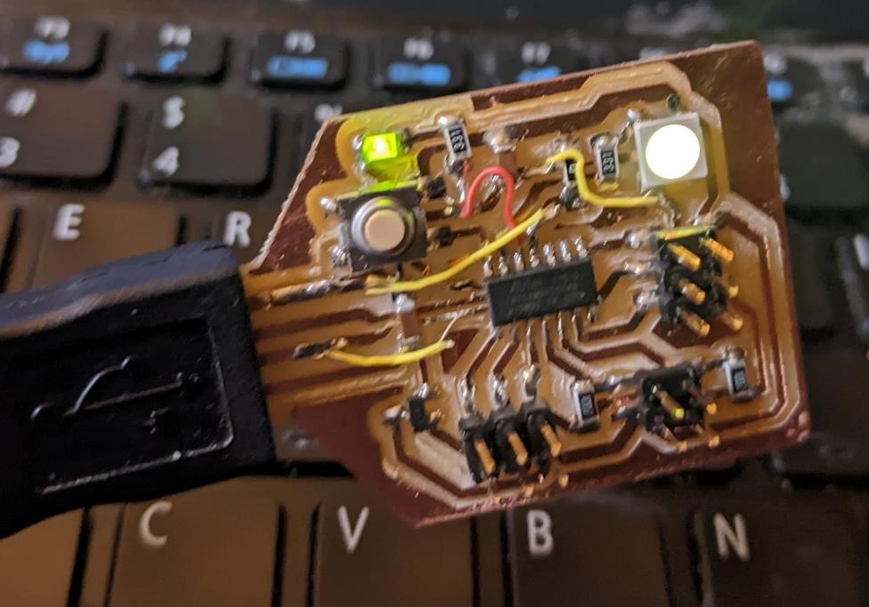
I had already made a previous version of the blink software, but that was on a board that did not have a neopixel led, just a basic, single color LED.
Instead, I needed to test the neopixel and make sure it worked, and that I could get multiple colors from it.
The first thing I needed however was a neopixel library. I had no intention of programming a neopixel the hard way (it defeats the purpose).
I searched for attiny412 and neopixel and came across this wonderful library that was already included with the attiny412 board manager definition for the attiny412 for arduino IDE. This is a version of the Adafruit Neopixel library designed for the Attiny line of processors. The document also has a lot of excellent information about Neopixels (and similiar RGB led’s) in it’s own right.
https://github.com/SpenceKonde/megaTinyCore/blob/master/megaavr/extras/tinyNeoPixel.md
Using this library, I esentially copied the code for the very example test code from Adafruit’s Neopixel Library for the Arduino
Neopixel Blink
The below is the code that I used, and is essentially a simple test that changes the neopixel color from green, to red, to blue, and repeats.
After a couple of errors changing the library references, and other information, I was able to get it working.
// https://github.com/adafruit/Adafruit_NeoPixel/blob/master/examples/strandtest/strandtest.ino
// and
// https://create.arduino.cc/projecthub/robocircuits/neopixel-tutorial-1ccfb9
// NeoPixel Ring simple sketch (c) 2013 Shae Erisson
// Released under the GPLv3 license to match the rest of the
// Adafruit NeoPixel library

#include <tinyNeoPixel.h>
// NeoPixel Ring simple sketch (c) 2013 Shae Erisson
// Released under the GPLv3 license to match the rest of the
// Adafruit NeoPixel library

// Which pin on the Arduino is connected to the NeoPixels?
#define PIN        4 // Garrett Attiny Neopixel Board

// How many NeoPixels are attached to the Arduino?
#define NUMPIXELS 1 // only 1 on og board

// When setting up the NeoPixel library, we tell it how many pixels,
// and which pin to use to send signals. Note that for older NeoPixel
// strips you might need to change the third parameter -- see the
// strandtest example for more information on possible values.
tinyNeoPixel pixels(NUMPIXELS, PIN, NEO_GRB + NEO_KHZ800);

#define DELAYVAL 500 // Time (in milliseconds) to pause between pixels

void setup() {

  pixels.begin(); // INITIALIZE NeoPixel strip object (REQUIRED)
  pixels.setBrightness(85); // about 1/3 brightness
}

void loop() {
  pixels.clear(); // Set all pixel colors to 'off'
  delay(DELAYVAL);
  // pixels.Color() takes RGB values, from 0,0,0 up to 255,255,255
  // Here we're using a moderately bright green color:
  pixels.setPixelColor(0, pixels.Color(0, 150, 0));
  pixels.show();   // Send the updated pixel colors to the hardware.
  delay(DELAYVAL); // Pause before next pass through loop
  pixels.clear();
  delay(DELAYVAL);
  pixels.setPixelColor(0, pixels.Color(150, 0, 0));  //red
  pixels.show();
  delay(DELAYVAL);
  pixels.clear();
  delay(DELAYVAL);
  pixels.setPixelColor(0, pixels.Color(0, 0, 150));  //blue
  pixels.show();
  delay(DELAYVAL);


}
Button test
After this, I wanted to test the Button on this board.
I searched and found this example code: https://arduinogetstarted.com/tutorials/arduino-button, which I had originally used for the button test on the plain LED board, and it worked. (though, I did have to change the “polarity” of the high/low of the “current state” of the button sensing, but after that, it worked fine.) and based my code off of this.
This version combines the neopixel code with the button sensing code. If the button is pushed (closed), the LED turns RED, if the button is open, then the LED stays BLUE.
// https://arduinogetstarted.com/tutorials/arduino-button
// and
// https://github.com/adafruit/Adafruit_NeoPixel/blob/master/examples/strandtest/strandtest.ino

#include <tinyNeoPixel.h>

const int BUTTON_PIN = 0;

#define PIN        4 // Garrett Attiny Neopixel Board
#define NUMPIXELS 1

tinyNeoPixel pixels(NUMPIXELS, PIN, NEO_GRB + NEO_KHZ800);

int currentState = LOW;    // the current reading from the input pin

void setup() {
    pixels.begin(); // INITIALIZE NeoPixel strip object (REQUIRED)
    pixels.setBrightness(85); // about 1/3 brightness
    pixels.clear();
    pinMode(BUTTON_PIN, INPUT_PULLUP);

}

void loop() {
    pixels.clear();
    currentState = digitalRead(BUTTON_PIN);

    if(currentState == LOW) {
       pixels.setPixelColor(0, pixels.Color(150, 0, 0));  //red
    }
    else
    {
        pixels.setPixelColor(0, pixels.Color(0, 0, 150));  //blue
    }
    pixels.show();

}
This code also worked, after I found a few transcription/dumb errors (forgetting “;” and etc.)
Rainbow Wheel
Next I wanted to dive a bit deeper into the Neopixel, and get other colors than simple Red, Green, and Blue.
While I’m only using 1 neopixel, the ability to have multiple colors can make a huge impact on the information that I receive from the board.
I found some “rainbow” color code from the Neopixel, once again based off of Adafruit’s library.
This code simply cycles the neopixel through a variety of colors.
//https://github.com/adafruit/Adafruit_NeoPixel/blob/master/examples/strandtest/strandtest.ino
//and
//https://create.arduino.cc/projecthub/robocircuits/neopixel-tutorial-1ccfb9
// NeoPixel Ring simple sketch (c) 2013 Shae Erisson
// Released under the GPLv3 license to match the rest of the
// Adafruit NeoPixel library
// Rainbow from https://codebender.cc/sketch:80438#Neopixel%20Rainbow.ino

#include <tinyNeoPixel.h>
// NeoPixel Ring simple sketch (c) 2013 Shae Erisson
// Released under the GPLv3 license to match the rest of the
// Adafruit NeoPixel library
// modified: sgn, March 2022


// Which pin on the Arduino is connected to the NeoPixels?
#define PIN        4 // Garrett Attiny Neopixel Board

// How many NeoPixels are attached to the Arduino?
#define NUMPIXELS 1 // only 1 on og board

// When setting up the NeoPixel library, we tell it how many pixels,
// and which pin to use to send signals. Note that for older NeoPixel
// strips you might need to change the third parameter -- see the
// strandtest example for more information on possible values.
tinyNeoPixel pixels(NUMPIXELS, PIN, NEO_GRB + NEO_KHZ800);

#define DELAYVAL 500 // Time (in milliseconds) to pause between pixels

void setup() {
  pixels.begin(); // INITIALIZE NeoPixel strip object (REQUIRED)
  pixels.setBrightness(85); // about 1/3 brightness
  pixels.clear();
}

void loop() {

  rainbow(30);
  delay (20);

}


void rainbow(uint8_t wait) {
  uint16_t i, j;

  for(j=0; j<256; j++) {
    for(i=0; i < pixels.numPixels(); i++) {
      // pixels.setPixelColor(0, pixels.Color(0, 150, 0));
      pixels.setPixelColor(i, Wheel((i*1+j) & 255));
    }
    pixels.show();
    delay(wait);

  }
}

//input a value 0 to 255 to get a color value
// the colors are transitions, r - g - g - back to r
uint32_t Wheel(byte WheelPos) {
  if (WheelPos < 85) {
    return pixels.Color(WheelPos * 3, 255 - WheelPos * 3, 0);
  }
  else if(WheelPos < 170){
    WheelPos -= 85;
    return pixels.Color(255 - WheelPos * 3, 0, WheelPos * 3);
  }
  else {
    WheelPos -= 170;
    return pixels.Color(0, WheelPos * 3, 255 - WheelPos * 3);
  }
}
This code took me a while to get working. There were issues with the transcription, I made a number of simple mistakes. But what really held me back is that I had put “for(i=0; i << pixels.numPixels(); i++)” instead of “for(i=0; i < pixels.numPixels(); i++)” There’s a double carrot (<<), which I believe is an assignment instead of an equivalence operator. That error took me about 10 minutes to track down. But once I changed it, I had a pretty rainbow pattern on my board.
But tracking down that error had a silver lining, it really forced me to go through the program and try to better understand it, and what it was doing. And while I don’t claim absolute knowledge on how this program operates, I do feel like I have a much better understanding now.
Rainbow Bright
The next thing I wanted to do was to better combine what I was doing with the Rainbow code with the button. My first idea was to have the neopixel led cycle through the different colors, but upon a push of the button, the cycle would stop, and the color would “stick” at that color until the button was released, and the cycle would continue.
I had more problems implementing this code. As of this writing, I’ve yet to gotten it to work.
It’s because the Rainbow function cycles all the way through before checking the status of the button press. I’m going to have to make big changes to the code in order to change this behavior I believe, but like so much of this, I don’t really know what I’m doing.
//https://github.com/adafruit/Adafruit_NeoPixel/blob/master/examples/strandtest/strandtest.ino
//and
//https://create.arduino.cc/projecthub/robocircuits/neopixel-tutorial-1ccfb9
// NeoPixel Ring simple sketch (c) 2013 Shae Erisson
// Released under the GPLv3 license to match the rest of the
// Adafruit NeoPixel library
// Rainbow from https://codebender.cc/sketch:80438#Neopixel%20Rainbow.ino
// and button: //https://arduinogetstarted.com/tutorials/arduino-button

// NeoPixel Ring simple sketch (c) 2013 Shae Erisson
// Released under the GPLv3 license to match the rest of the
// Adafruit NeoPixel library
// modified: sgn, March 2022

#include <tinyNeoPixel.h>


// Which pin on the Arduino is connected to the NeoPixels?
#define PIN        4 // Garrett Attiny Neopixel Board

// How many NeoPixels are attached to the Arduino?
#define NUMPIXELS   1 // only 1 on og board

#define DELAYVAL  500 // Time (in milliseconds) to pause between pixels

const int BUTTON_PIN = 0;

int currentState = LOW;    // the current reading from the input pin


// When setting up the NeoPixel library, we tell it how many pixels,
// and which pin to use to send signals. Note that for older NeoPixel
// strips you might need to change the third parameter -- see the
// strandtest example for more information on possible values.
tinyNeoPixel pixels(NUMPIXELS, PIN, NEO_GRB + NEO_KHZ800);


void setup() {
  pixels.begin(); // INITIALIZE NeoPixel strip object (REQUIRED)
  pixels.setBrightness(35); // about 1/3 brightness
  pixels.clear();
  delay(10);
  pinMode(BUTTON_PIN, INPUT_PULLUP);


}

void loop() {
  pixels.clear();
  currentState = digitalRead(BUTTON_PIN);
  if(currentState == HIGH) {
      pixels.clear();
      rainbow(30);
      delay (20);
      pixels.show();
  }
  else {
    pixels.setPixelColor(0, pixels.Color(20, 150, 200));  //blue
    delay(10);
  }
  pixels.show();
  delay(10);
}


void rainbow(uint8_t wait) {
  uint16_t i, j;

  for(j=0; j<256; j++) {
    for(i=0; i < pixels.numPixels(); i++) {
      pixels.setPixelColor(i, Wheel((i*1+j) & 255));
    }
    pixels.show();
    delay(wait);

  }
}


//input a value 0 to 255 to get a color value
// the colors are transitions, r - g - g - back to r
uint32_t Wheel(byte WheelPos) {
  if (WheelPos < 85) {
    return pixels.Color(WheelPos * 3, 255 - WheelPos * 3, 0);
  }
  else if(WheelPos < 170){
    WheelPos -= 85;
    return pixels.Color(255 - WheelPos * 3, 0, WheelPos * 3);
  }
  else {
    WheelPos -= 170;
    return pixels.Color(0, WheelPos * 3, 255 - WheelPos * 3);
  }
}
Turquoise Wave
This is code for my 16 Neopixel Attiny412 that fills in each pixel, first vertically, while making each pixel more of a greenish tint, and then clearing each pixel horizontally. This is practice with for loops and better understanding how to control individual neopixels.
//https://github.com/adafruit/Adafruit_NeoPixel/blob/master/examples/strandtest/strandtest.ino
//and
//https://create.arduino.cc/projecthub/robocircuits/neopixel-tutorial-1ccfb9
// NeoPixel Ring simple sketch (c) 2013 Shae Erisson
// Released under the GPLv3 license to match the rest of the
// Adafruit NeoPixel library

#include <tinyNeoPixel.h>
// NeoPixel Ring simple sketch (c) 2013 Shae Erisson
// Released under the GPLv3 license to match the rest of the
// Adafruit NeoPixel library

// Which pin on the Arduino is connected to the NeoPixels?
#define PIN        4 // Garrett Attiny Neopixel Board

// How many NeoPixels are attached to the Arduino?
#define NUMPIXELS 16 // only 1 on og board

// When setting up the NeoPixel library, we tell it how many pixels,
// and which pin to use to send signals. Note that for older NeoPixel
// strips you might need to change the third parameter -- see the
// strandtest example for more information on possible values.
tinyNeoPixel pixels(NUMPIXELS, PIN, NEO_GRB + NEO_KHZ800);

#define DELAYVAL 100 // Time (in milliseconds) to pause between pixels

uint16_t i, j;
uint8_t n = 0;

void setup() {
  pixels.begin(); // INITIALIZE NeoPixel strip object (REQUIRED)
  pixels.setBrightness(25); // about 1/4 brightness
}

void loop() {
  pixels.clear(); // Set all pixel colors to 'off'
  // delay(DELAYVAL);
  // pixels.Color() takes RGB values, from 0,0,0 up to 255,255,255
  for(j=0; j < pixels.numPixels()/4; j++) {
     for(i=n; i < pixels.numPixels(); i = (i+4)) {
        pixels.setPixelColor(i, pixels.Color(0, (i*15+20) & 255, 20+(i*2)));
        delay(DELAYVAL);  //change DELAYVAL for speed increase/decrease
        pixels.show();
     }

  n++;  //keep track of how many times we cycle through everything. increment by one.
  }

  // this clears each pixel in it's turn.
  for(i=0; i < pixels.numPixels(); i++) {
     pixels.setPixelColor(i, pixels.Color(0, 0, 0));
     delay(DELAYVAL);
     pixels.show();
  }

  // this resets the pattern after 4 times.
  if (n == 4)
  {
    n = 0;
  }
}
Bare Metal Programming the ATtin412
The “Bare Metal” programming is essentially just using a C Compiler and the Data Sheet of the chip, to set many of the registers and the actual pins directly, without using a library or other basic higher level interfaces (other than C itself, which is a higher level programming language) to write code. (But everyone know that real coders only use Assembly to write their programs.)
I followed this tutorial: https://www.youtube.com/watch?v=tBq3sO1Z-7o to get started (David Taylor sent me this link.)
But I actually found his second video: https://www.youtube.com/watch?v=W8REqKlGzDY much more helpful in understanding registers, memory and pointers.
and started working on the code.
void setup(){
  DDRB = 32; //00100000 sets PB5 as output
}

void loop() {
  PORTB = 32;
  for (long i = 0; i < 1000000;; i++) {PORTB = 32;}
  PORTB = 0;
   for (long i = 0; i < 1000000;; i++) {PORTB = 0;}
}
I’m still trying to dial this in. I should have it done soon.
But the other thing I wanted to try was Neil’s Ring Oscillator test.
The code for this can be found from this link: https://pub.pages.cba.mit.edu/ring/GPIO/ATtiny412/ring.t412.ino
And essentially I just retyped his code (though I did directly copy the copyright notice.)
//
// ring.t412.ino
//
// ATtiny412 ring oscillator test
//
// Neil Gershenfeld 11/13/20
//
// This work may be reproduced, modified, distributed,
// performed, and displayed for any purpose, but must
// acknowledge this project. Copyright is retained and
// must be preserved. The work is provided as is; no
// warranty is provided, and users accept all liability.
//


void setup() {
  CPU_CCP = CCP_IOREG_gc; //unprotect clock
  CLKCTRL.MCLKCTRLB = 0; // Turn off Prescaler (20 Mhz)
  PORTA.DIRSET = PIN6_bm; // set output pin
}

void loop() {
  while(1) {

    // VPORT 1.808 MHz
    // 250 ns high (5 cycles), 300 ns low (6 cycles)

    if (VPORTA.IN & PIN7_bm)
       VPORTA.OUT &= ~PIN6_bm;
    else
       VPORTA.OUT |= PIN6_bm;

    /*
    // PORT: 1.056MHz
    if (PORTA.IN & PIN7_bm)
       PORTA.OUTCLR = PIN6_bm;
    else
        PORTA.OUTSET = PIN6_bm;

    //digitalRead/Write 0.331 Mhz
    if (digitalRead(1))
       digitalWrite(0,LOW);
    else
       digitalWrite(0,HIGH);

    //digitalRead/Write 1.808 Mhz
    if (digitalReadFast(1))
       digitalWriteFast(0,LOW);
    else
       digitalWriteFast(0,HIGH);
    */
  }
}
Programming the SAMD11C boards…
WIP
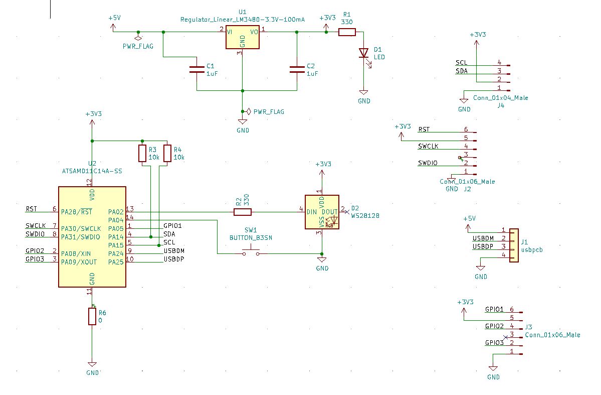
I continued with the SAMD11C Accelerometer board I had designed previously. This board was soldered up, and hopefully I didn’t burn up the ADXL343 chip, or create any solder connections. These chips are just not easy to work with.
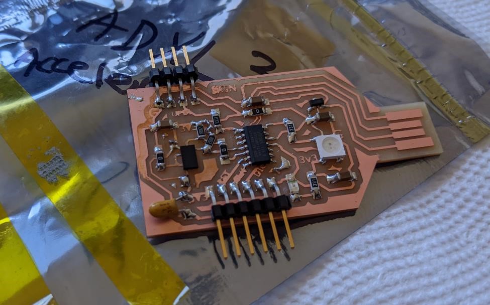
(You may notice a slight bodge in the above image. I had to add 10k pullup resistors for the SCL and SDA interface. One of these was simple and fit perfectly. The other was less so and much more of an obvious hack.)
I originally used a Raspberry Pi to install bootloaders onto the Adam Harris designed SAMD11C14 programming board, found here: https://sheekgeek.org/2022/adamsheekgeek/samd11c-multi-use-board. But I wanted to use these programmers to program another SAMD11C board, which I have yet to do.
Adam’s design is capable of programming with 3 different systems, over serial and UART, over UPDI, and over JTAG. However, for JTAG, it needs a different software installed on the board. I need to install new software on one of my SAMD11C based programming boards to use the JTAG system (all of mine are currently set up for UPDI). And I’ve going to do so using the Raspberry Pi Again.
I followed the instructions from Adrian Torre’s site. https://fabacademy.org/2020/labs/leon/students/adrian-torres/samdino.html and from Adam’s site (link above), in order to get an idea about the workflow.
And I combined them with the instructions that I used with the Raspberry Pi from Week 5 - Electronics Production. I’ve said it before, but one thing about doing a decent job of documenting what I’ve done before, it saves me from having to completely remember what I did before, and having to guess and relearn it all.
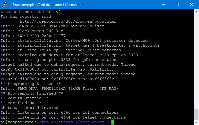
I downloaded the FreeDAP bootloader bin file from here: http://academy.cba.mit.edu/classes/embedded_programming/SWD/free_dap_d11c_mini.bin using wget.
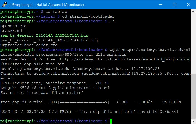
And with the proper connections to the Programming board via the Raspberry Pi, as I had already prepared the Raspberry Pi and installed the proper software (OpenOCD) I was almost ready to go through the previous procedures to upload the file.
(As I was doing this, I noticed that the SAMD11C chip was warm to the touch, being programmed, and the LOD 3.3v regulator was downright HOT!)
But you need to change which file you’re uploading.
sudo nano openocd.cfg
I then changed the line in openocd.cfg:
program sam_ba_Generic_D11C14A_SAMD11C14A.bin verify
to the new programmer code and bin file:
program free_dap_d11c_mini.bin verify
I saved the file.
and I ran the program with:
sudo openocd
For whatever reason, it took multiple tries to get this to actually work. I simply tried again and again, and on the 4th try, it worked, and the chip was programmed. I’m not sure the reason for this, and it’s quite odd. But hey, it worked.
Now this programmer should be ready to program other SAMD11C chips and JTAG devices.
I’ve actually got to go find a board, and the time, to program it.
For Future Reference
The pinout for connecting the board to another board is the following (Borrowed from Adam Harris). And while my SAMD11C board is different, it’s heavily influenced by Adam’s board, and the pin connections are still going to remain the same.
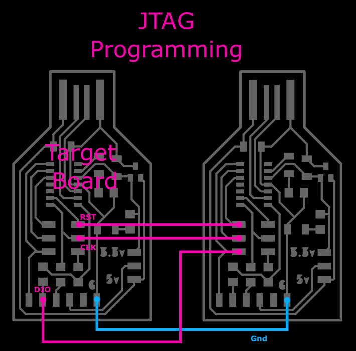
Note that the above programmer does not have a 3.3v or 5v connection. I connected mine up the same way.
Going back to Adrian Torre’s site. https://fabacademy.org/2020/labs/leon/students/adrian-torres/samdino.html I used his examples to help program another board.
I downloaded EDBG r32 from here: https://taradov.com/bin/edbg/
and used the same sam_ba_SAMD11C14A.bin file as for the other programmers: https://github.com/qbolsee/ArduinoCore-fab-sam/blob/master/bootloaders/zero/binaries/sam_ba_SAMD11C14A.bin
Then I ran edbg.
edbg-windows-r32.exe -ebpv -t samd11 -f sam_ba_SAMD11C14A.bin
And… Nothing.
I tried adding the 5v line, but this actually killed the LED on the programmer. This immediately made me suspicious. Due to learning a lesson from Cori’s exploding board, I grabbed a 5v phone wall charger and plugged my board directily into this.
And I saw smoke coming off of my board. So I immediately yanked it out. But this is an indication that I have a very major short somewhere on the board.
And looking at it, I noticed a major issue. I placed the USB plug backwards, that is, reversed the GND and 5v locations. Oh man.
But even though it’s on the board, it’s not being used to program, and as such, there’s another major issue somewhere.
And with that, I’m going to have to experiment with this another day.
(However, I do have another board design…)
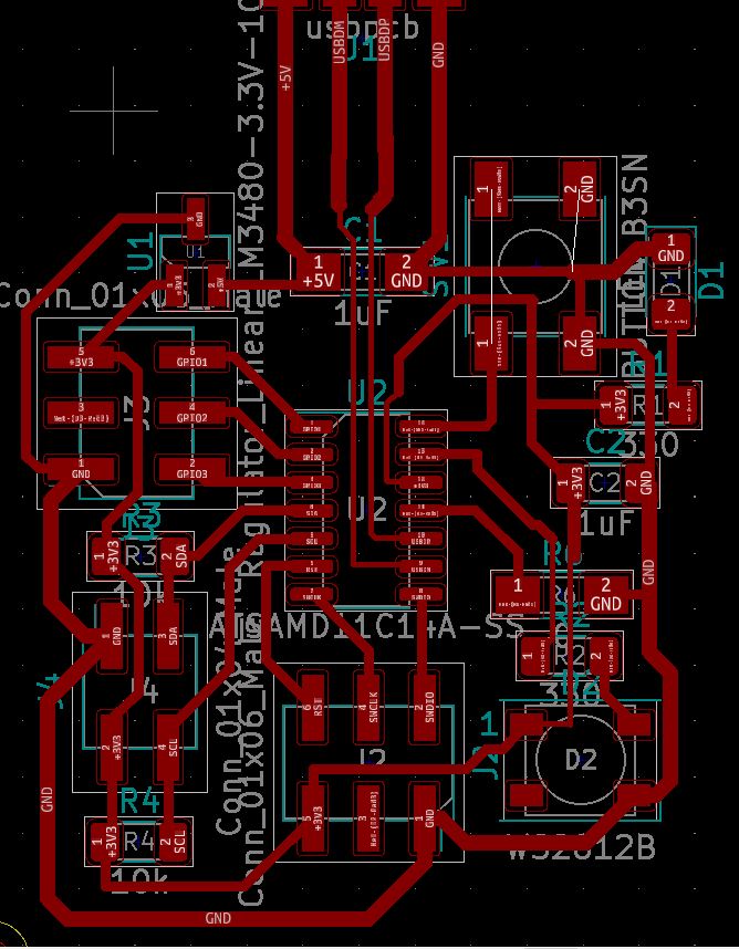
PNG’s for milling:

Update: Made it. It works. Even managed to save one that the mill and very bad tape tried to destroy.
Update
I found a couple of problems with the original board.
1) Dumb as dirt, I had switched the GND and 5v line for the USB A connector. Yeah. Wow. When I plugged it in to a power adapter, the regulator started smoking. Thankfully, I had learned from Cori’s board, that when plugged in, if the power led isn’t coming on, it’s probably a power short. And so, at least I was ready to yank this out as soon as I gave it power. I replaced the regulator, but still there was an issue.
But I found out the simple problem with the USB power lines and reversed them using jumper wires. But I was still seeing a short. I was able to just track this down the other evening.
2) It was the accelerometer, the pins for power and ground are right next to each other, and with such a tiny footprint, with such difficulty soldering it with the setup I had, it must have created some type of solder bridge.
In order to fix this, I unsoldered the chip with a hot air gun, re-applied solder paste and then soldered a new chip on. I don’t know if the accelerometer works, but at least now I don’t detect any shorts and when I plug this in, the power LED comes on.
Programming … again
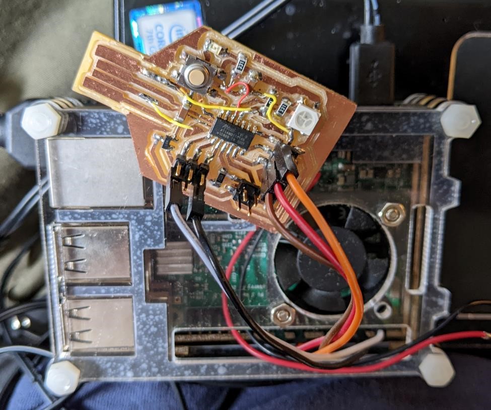
This time, I was able to connect the programmer I had last programmed, for JTAG/SWD, and using the above diagram connected to my new board, with RESET/CLOCK/DIO, 5v Ground. And that was one thing I did do, I connected the 3.3v line from the programmer to the target board.
and running:
edbg-windows-r32.exe -ebpv -t samd11 -f sam_ba_SAMD11C14A.bin
The board seemed to have been programmed. Easy enough. And when I plugged it in, windows detected it. That’s a good sign.
And btw, I follwed instructions from https://fabacademy.org/2020/labs/leon/students/adrian-torres/samdino.html
Another update on programming.
I had made a couple of other boards. I had accidentally programmed one board as a programmer (though it was not intended to be.) using the raspberry pi setup. And while I changed the openocd.cfg file and re-programmed it, and it programmed and verified just fine, I couldn’t get the USB to be recognized in windows or in Linux.
I decided to re-program it with the typical Adam Harris programmer. I tried using the programmer and edbg in windows and I received this error:
C:\Users\Garrett Nelson\Downloads>edbg-windows-r32.exe -ebpv -t samd11 -f sam_ba_SAMD11C14A.bin
Debugger: Alex Taradov Generic CMSIS-DAP Adapter 886CAD11 v0.1 (S)
Clock frequency: 16.0 MHz
Target: SAM D11C14A (Rev B)
Erasing... done.
Programming.... done.
Verification...
at address 0x0 expected 0xfc, read 0xff
Error: verification failed
Searching around, of course I found a FabAcademy page with similiar from Atsufumi Suzuku from Kamakura.
Using “edbg-windows-r32.exe -b -t samd11 -F w,2:0,7” he’s re-writing the fuses to the chip.
C:\Users\Garrett Nelson\Downloads>edbg-windows-r32.exe -b -t samd11 -F w,2:0,7
Debugger: Alex Taradov Generic CMSIS-DAP Adapter 886CAD11 v0.1 (S)
Clock frequency: 16.0 MHz
Target: SAM D11C14A (Rev B)
Fuses:
  writing value 0x7 to bits 2:0 in section 0: OK
done.
He had code to re-program the fuses. I then tried the reprogramming again with the sam_ba_SAMD11C14A.bin and it programmed and verified successfully.
Hooked it up to the computer, was recognized, and was able to program it with Arduino IDE.
I believe that this is due to programming the board with the “free_dap_d11c_mini.bin” first. I’ve thought I’ve done this in the past, but I’m probably mis-remembering, and this was the first time I’ve actually done it, and came across this problem. I’m glad Kamakura was there to help me fix it.
Group Project
You can find our group project here for now: Unit 9 Group Project
I learned a lot about making boards that don’t blow up as soon as you plug them in.
I also learned a lot from asking Denny about how to use different boards and what’s going on between them. He explained to me what was going on when you have two different boards/microprocessors that are operating at different logic levels (like a 3.3v and 5v board) and how you can use a simple resistor to help with allowing them to communicate (though Denny did emphasize you wouldn’t do this for a commercial product.)
We learned about the different architectures, and which architectures may be best for different purposes (such as a raspberry pi is a computer, versus something like a PIC which is a fairly simple microprocessor but has a number of uses.)
And I continued to learn about how to use these microprocessors, and how to program them.
But in reality, I know very little about any of this, and I’ve got a long ways to go before I can read a datasheet and have any idea what the vast majority of it actually means.
References and Resources
Most of the references are listed above in the documentation.
Files
The files for the boards and code are listed throughout this documentation