

Index
Introduction
During my Fab Academy I worked with the new ATtiny, the ATtiny412, ATtiny1614 and the ATtiny3216. But as a novelty this year there were also the new ARM microcontrollers with JTAG such as the SAMD11.
For this I want to document on this page, the process of creating the programmer, as well as the SAMDino board that is similar to the Adrianino where you can connect different sensors or actuators and go testing to continue working on the Hello World project.
To carry out the following project and the documentation I have consulted the documentation of Quentin Bolsee and Florent Lemaire, as well as the advice of the instructor Nicolas De Coster. Thank you. 🤗
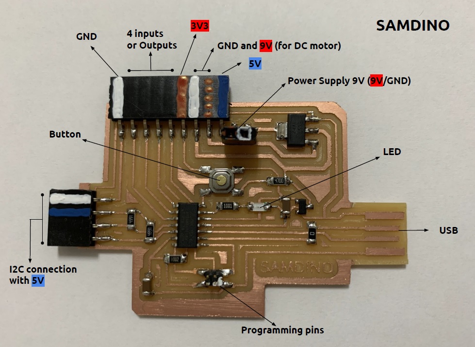
Features
- Via USB you can directly program and read data from a sensor.
- It contains a voltage regulator to power the board with a power supply (9V battery).
- It has another 9V power connection to for example power a DC motor driver.
- Then there are 4 outputs or inputs with VCC and GND on each side to be able to connect different inputs or outputs.
- On the left there is an I2C connection to connect an LCD, OLED or a sensor that uses this communication. Working in progress. Still not working.
- There is an LED and an integrated button, which will help us to test that the microcontroller works with a simple program.
- Possibility of connection with the Adrianino input and output modules.
Datasheet
SAM D11C 14A
A new generation of Atmel microcontrollers with SAMDs. A low-power, high-performance ARM® Cortex®-M0 + based flash microcontroller and with a full-speed USB device.
- 14 pin package.
- Internal and external clock options with 48MHDigital Frequency Locked Loop (DFLL48M) and 48MHto 96MHFractional.
- 16 KB Flash Memory.
- 256 B EEPROM.
- 4 KB SRAM.
- Maximum voltage: 3.63 V; minimum voltage: 1.62 V.
After looking at the basic features, you will find the pinning of the microcontroller. More information in this link.
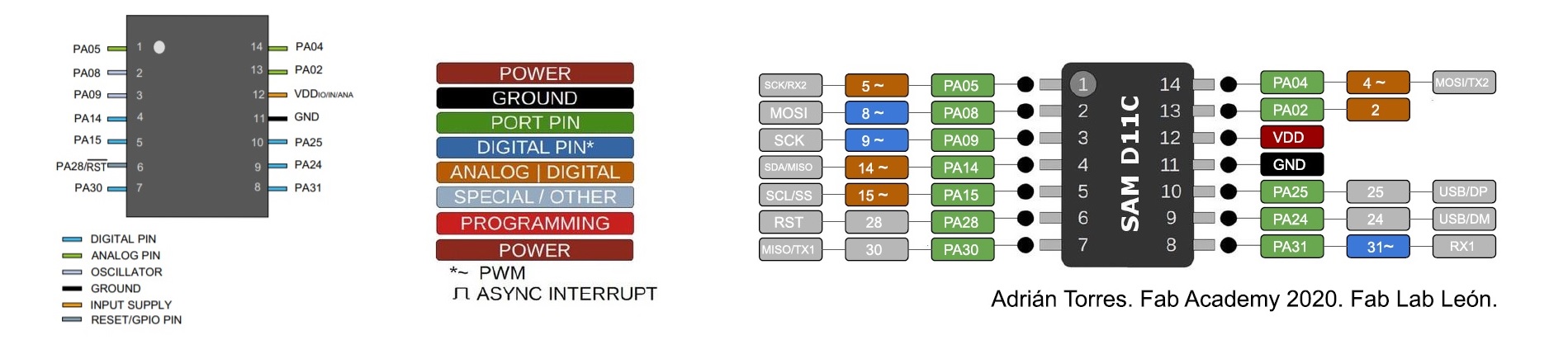
- VDD: Supply voltage.
- GND: Ground.
- Digital pins: PA02, PA04, PA05, PA08, PA09, PA14, PA15, PA31.
- Analog pins: PA02, PA04, PA05, PA14, PA15.
- USB pins: PA24, PA25.
All I/O pins can be configured with internal pull up or pull down resistance.
Within the communications section there are different types and their pins are different. It is clear that the different communication protocols cannot all be used at the same time, because they have pins in common.
- USART - Universal Synchronous and Asynchronous Receiver and Transmitter: It has the RX (PA31 or PA05) and the TX (PA30 or PA04).
- SPI - Serial Peripheral Interface: It has only MOSI (PA04 or PA08), MISO (PA14 or PA30), SCK (PA09), SS (PA15) .
- TWI - Two Wire Interface (I2C): It has SDA (PA14) and SCL (PA15).
Another important thing that the datasheet is telling us is that you have to keep in mind which kind of input component you are using, digital or analog: for instance, if you are using a temperature sensor (analog component) you have to connect it to an ACD (analog to digital converter) port otherwise the microcontroller isn't able to transform the information that is receiving from the sensor to a digital data.
SAMD11C Free Dap Programmer.
To work with this type of microcontrollers we need a programmer with JTAG. For this we can use the Atmel-ICE or the Particle. But the ideal is to create a Free Dap programmer using a SAMD11C.
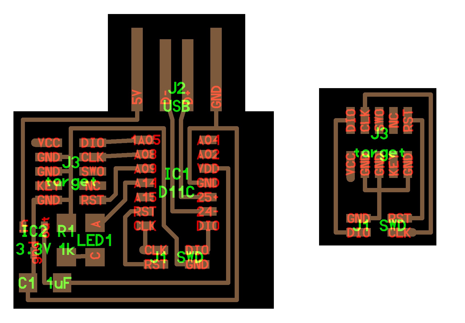
Following Neil's documentation on the Embedded Programming class we will find two types of programmers, the hello.CMSIS-DAP.10.D11C and the hello.CMSIS-DAP.4.D11C. In my case I will use the latter together with the hello.SWD.10-4 converter.
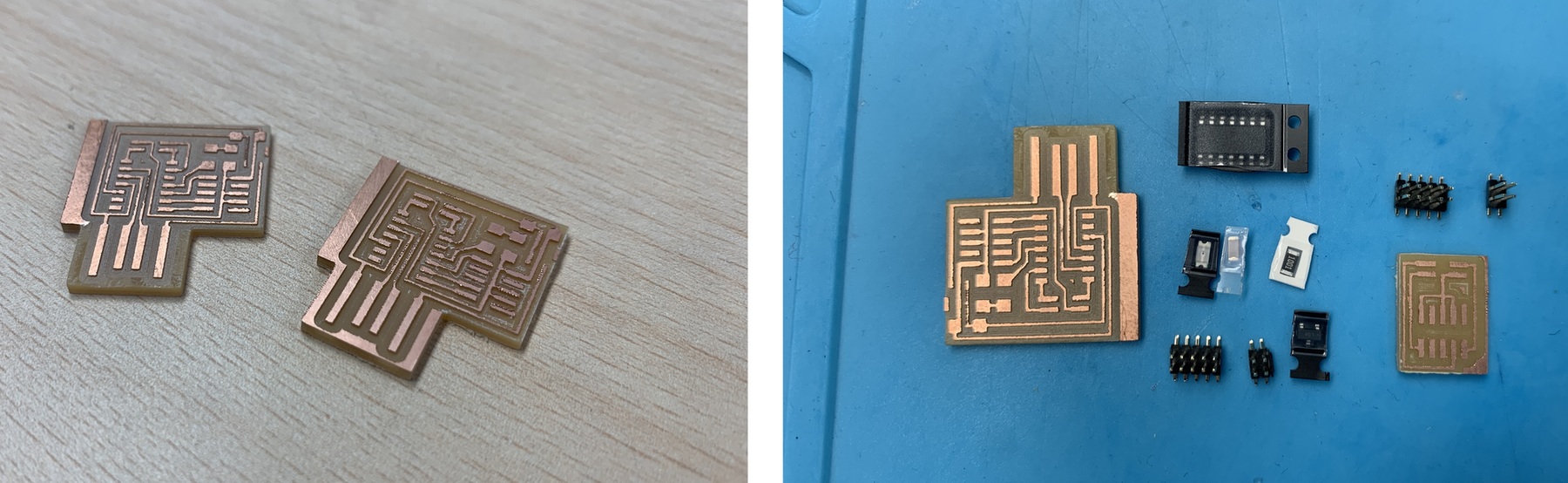
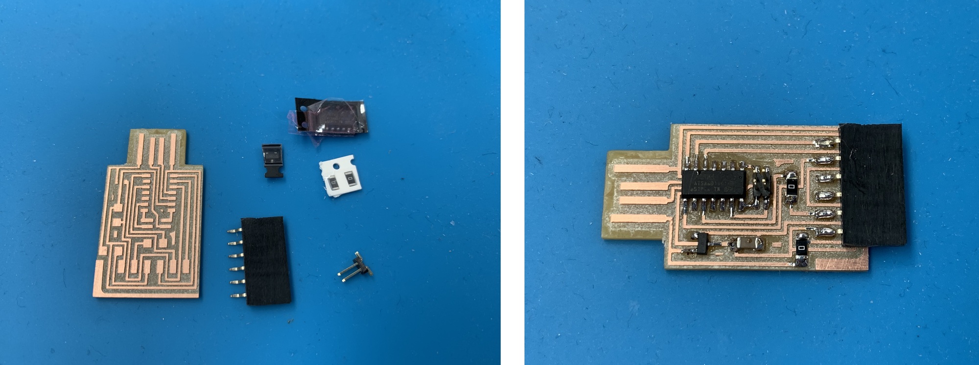
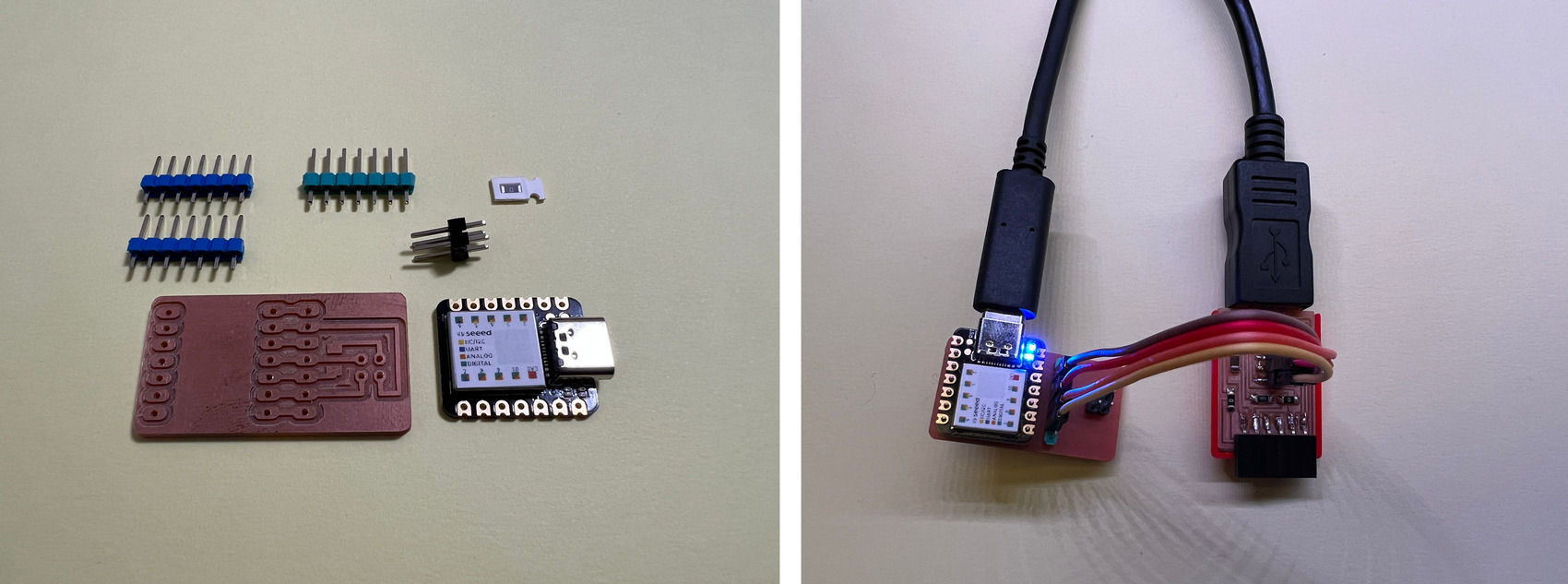
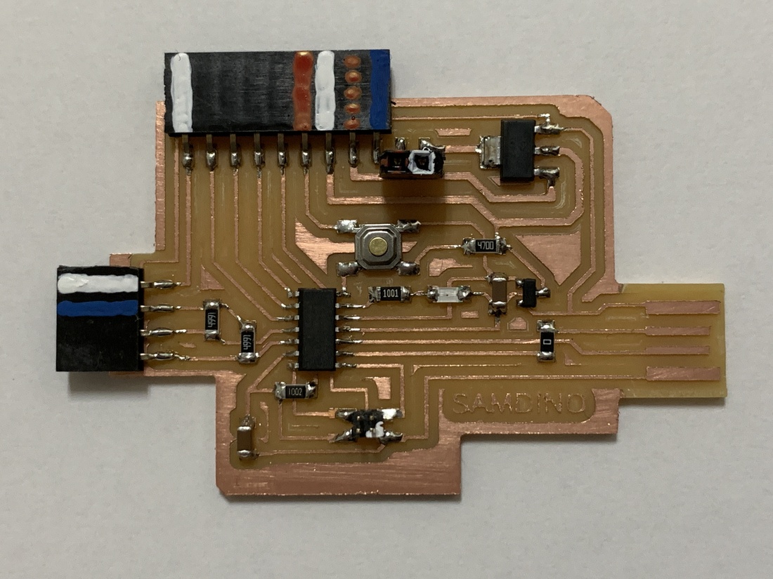
Here you can see the boards already milled. IMPORTANT: remember to remove the excess copper around the USB, you could produce a short circuit. The other image with the BOM prepared.
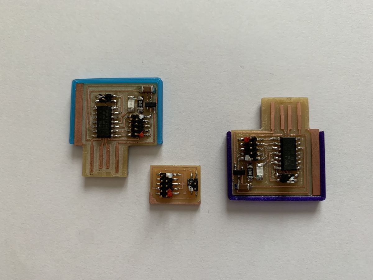
Once all the components have been soldered, I have created a 3D case to make a better connection of the USB and I have also painted the red color for VCC and the white color for GND on the 1.27 mm SMD connectors. So when connecting flat cables there is no confusion.
Programming
Create a SAMD11C Free Dap Programmer. (Windows)
As I mentioned in the previous step, one of the advantages of this microcontroller is that we can turn it into a programmer. For this we need Atmel-ICE or Particle programmer. In my case I use the Particle.
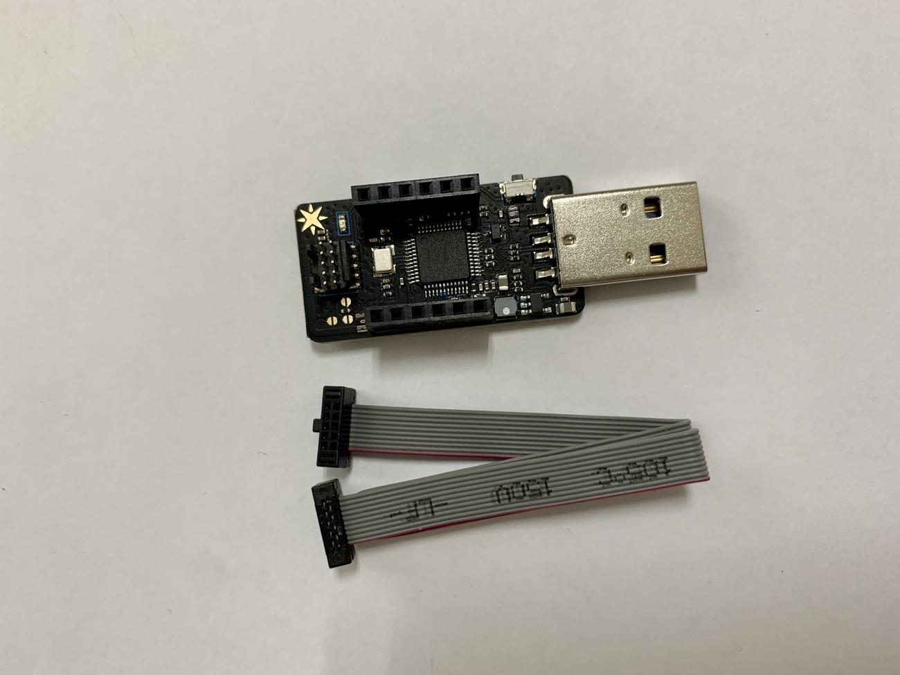
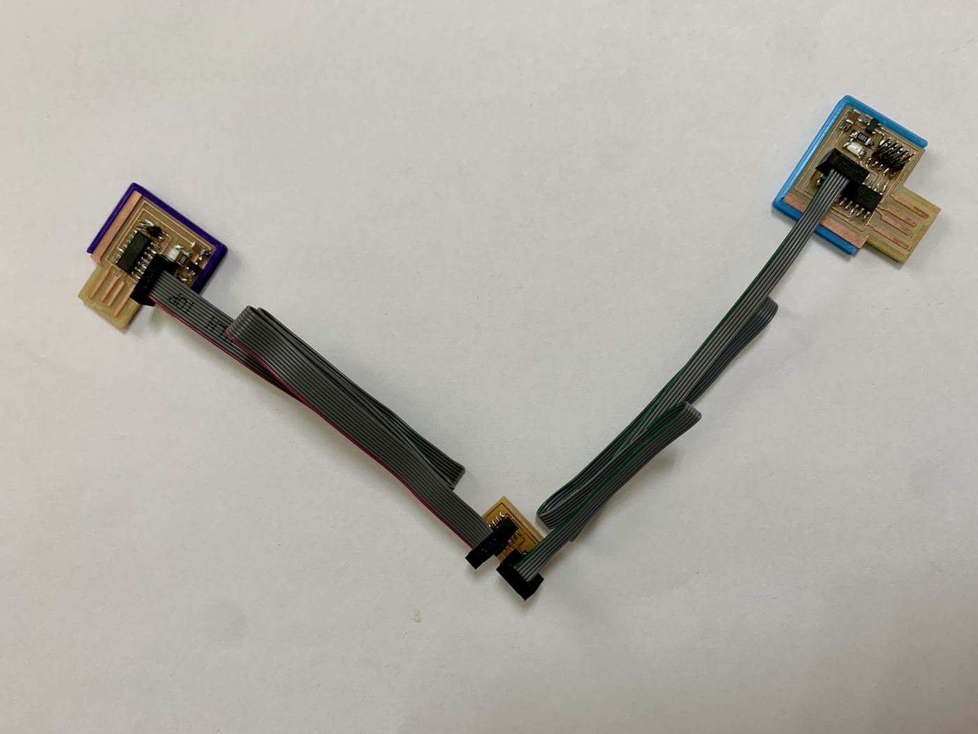
We will connect the flat cables in the following way, from the Particle to the 10-4 converter, then with the 4-wire flat cable (in my case, 6-wire) to the future programmer.
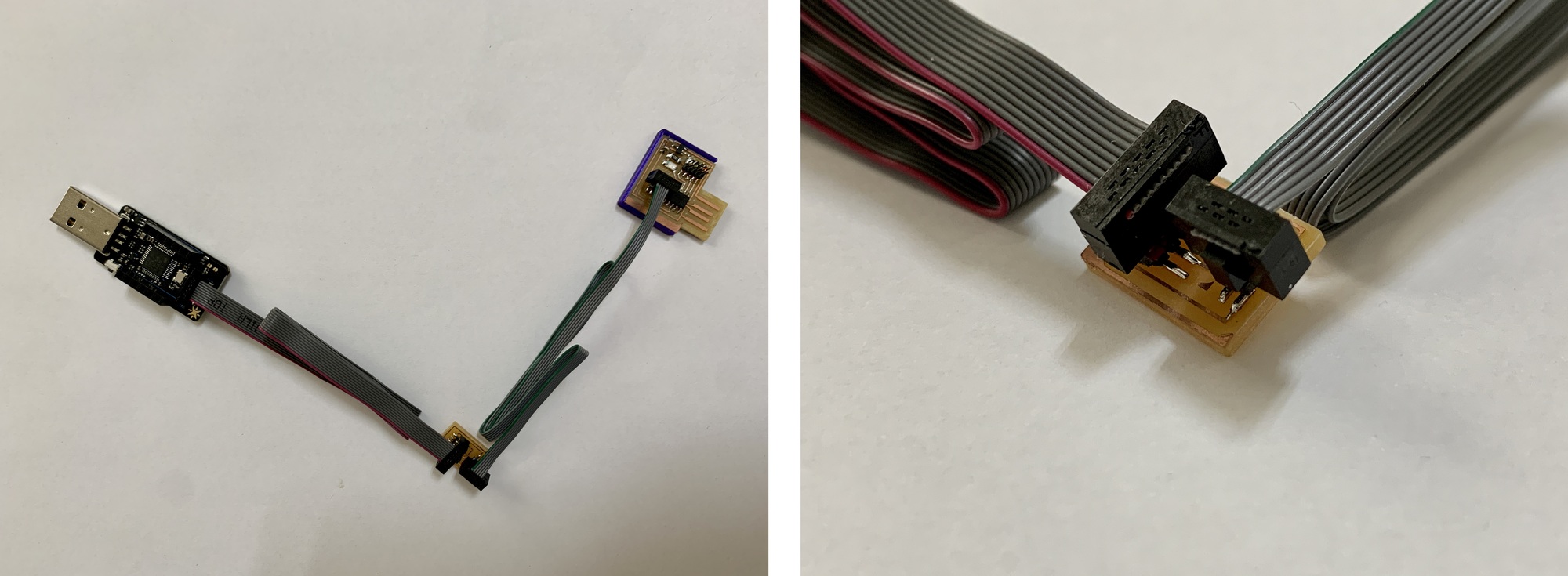
IMPORTANT: We will connect the Particle or the programmer to the computer and our Free Dap Programmer to an external power supply (that is not the same computer).
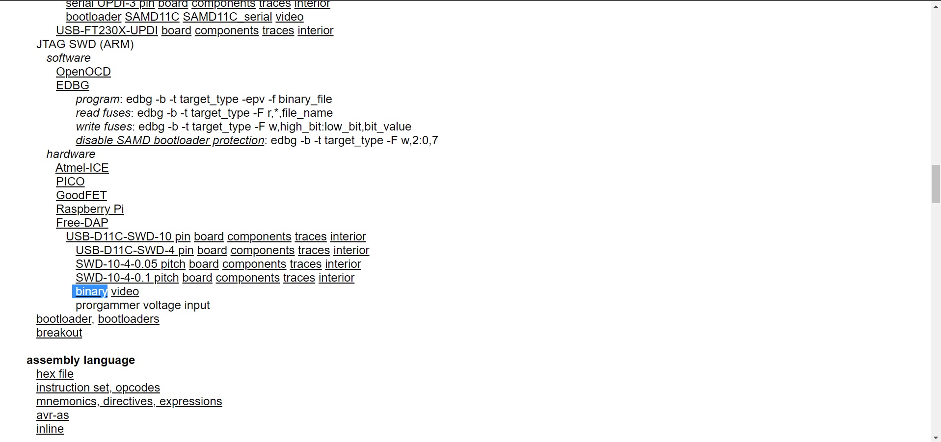
- 1. We will download the EDBG, in my case I download the 24 version.
- 2. Then on the Fab Academy page (Embedded Programming) we will find the Free Dap bootloader that we will also download. The bootloader has to be inside the EDBG folder.
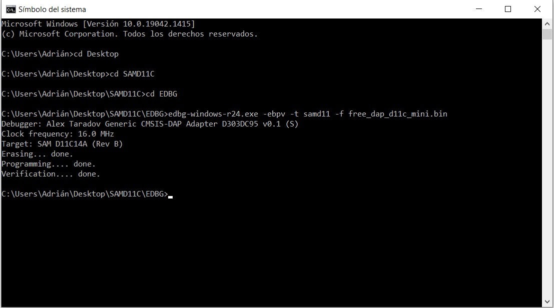
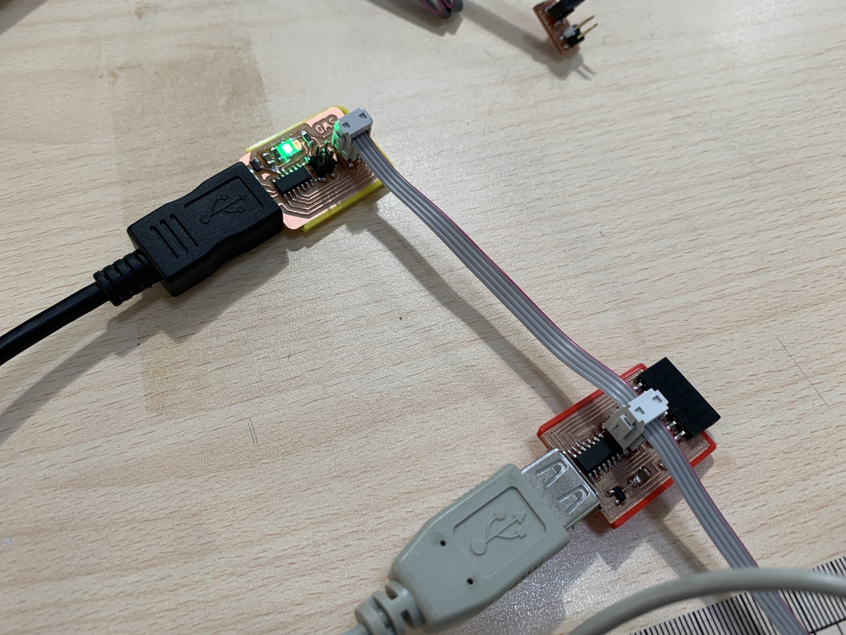
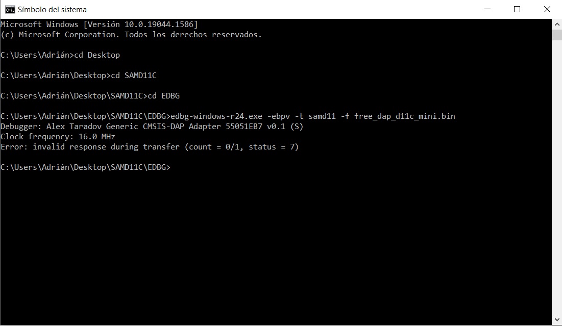
- 3. Open terminal. We execute inside the EDBG folder edbg-windows-r24.exe -ebpv -t samd11 -f free_dap_d11c_mini.bin The LED of our programmer should light up and appear on our screen like the following capture.
With this programming we get a programmer, now we can program other SAMD11C and have our own programmer or for the Fab Lab. This would be the connection, remember to feed the programmer to the computer and the future programmer to an external power source. Then we repeat the previous steps and program it.
SAM11C with Arduino
Once we have the SAMD11C as a Free Dap programmer, we can change the bootloader so that we can program the SAMD11C through the Arduino IDE. For this we will follow the following steps. You can find more information on the Mattairtech Git Hub, but better is the one on GitHub by Quentin Bolsee (ArduinoCore-Fab-SAM), who thanks to him has optimized the bootloader for the entire SAMD family with Arduino.
- 1. We will download the sam_ba_Generic_D11C14A bootloader. You need to have the EDBG downloaded. The bootloader has to be inside the EDBG folder.
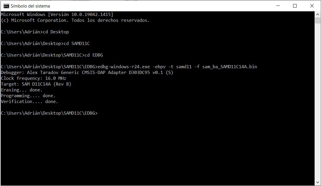
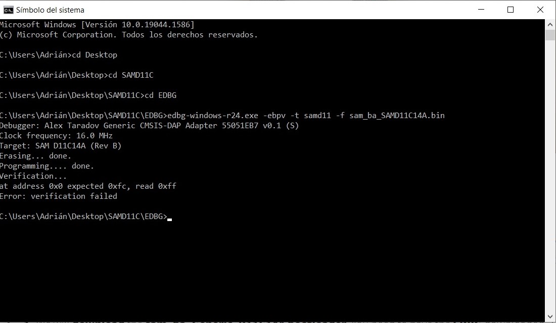
- 2. Open terminal. We execute inside the EDBG folder edbg-windows-r24.exe -ebpv -t samd11 -f sam_ba_SAMD11C14A.bin Appear on our screen like the following capture.
- 3. We disconnected the Free-Dap programmer from our SAMD11C. Now we connect the SAMD11C to the computer.
- 4. We open the Arduino program.
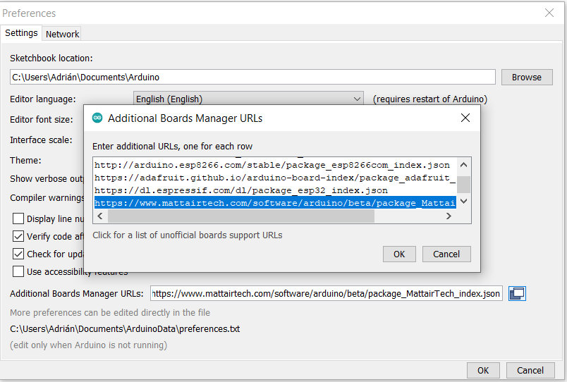
- 5. In Preferences, we will add the URL of the additional cards that you can find here. We need the MattairTech LLC.
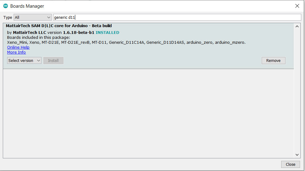
- 6. The next step is to download Generic SAMD11C in the boards manager.
- 7. We configure the Arduino IDE for the SAMD11C. The SAMD11C will appear in the COM port, in my case in COM 8.
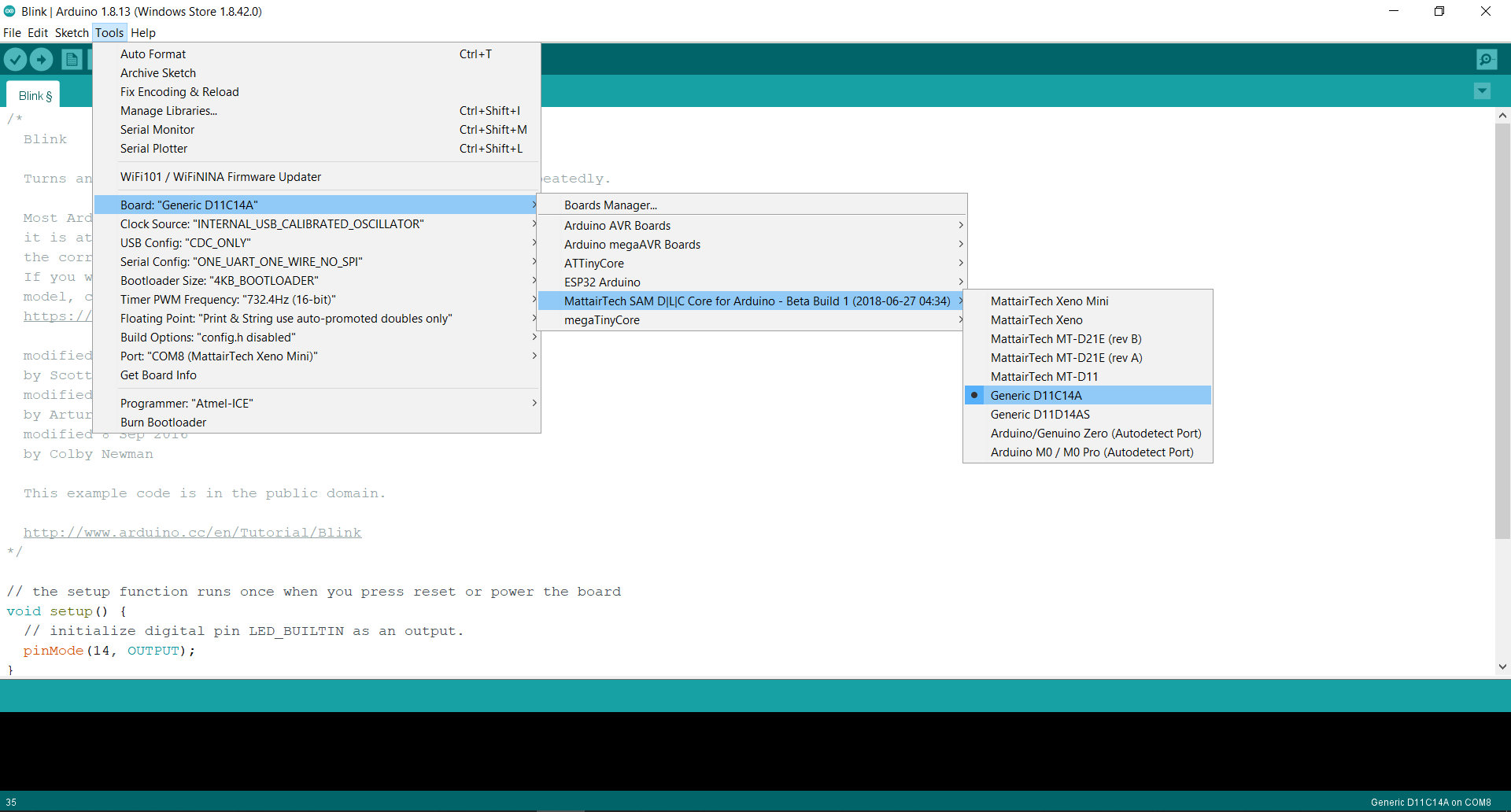
- 8. Now load the Blink program so that the LED on pin 14 blinks. When we upload it, all this information appears in the notifications section.
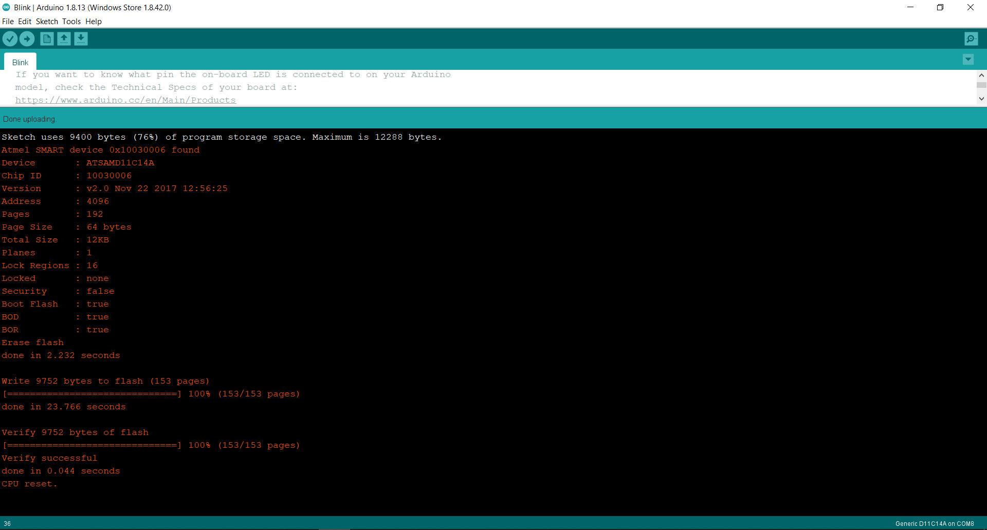
In this short video you can see the operation of a Blink on pin PA14 (14 in Arduino) where the LED is integrated. 😍
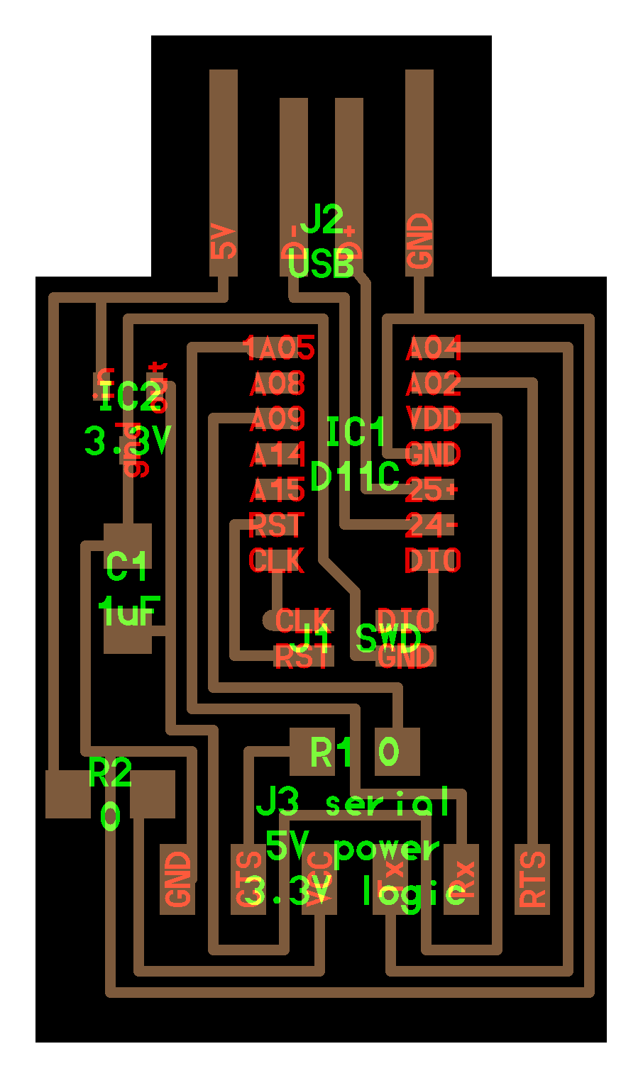
SAMD11C SWD
During the Instructors Bootcamp held in Oulu, different working groups were created. One of them was the creation of an easier to use and program SAMD11C programmer with larger pin headers. Thanks to Krisjanis Rijnieks the first version and Henk Buursen with this version has LED's.😍
For this in the project repository you can find more information.
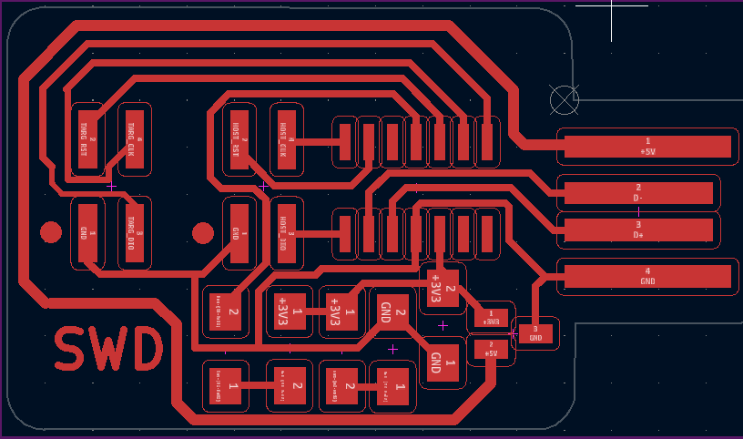
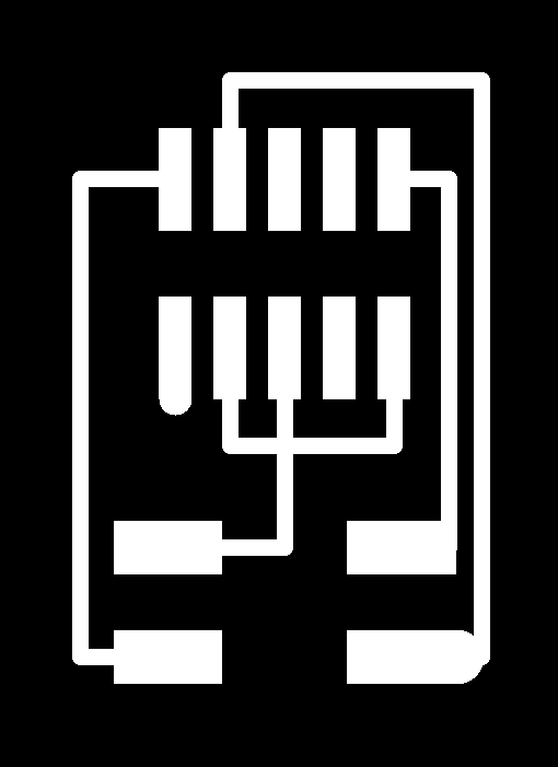
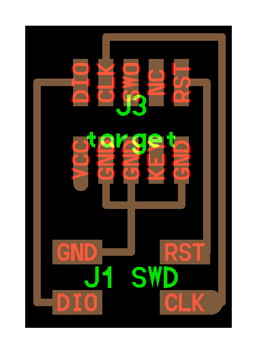
The first thing we will do is download the following PNG or SVG files to create the board. You can find them in the Programmer SWD D11C.
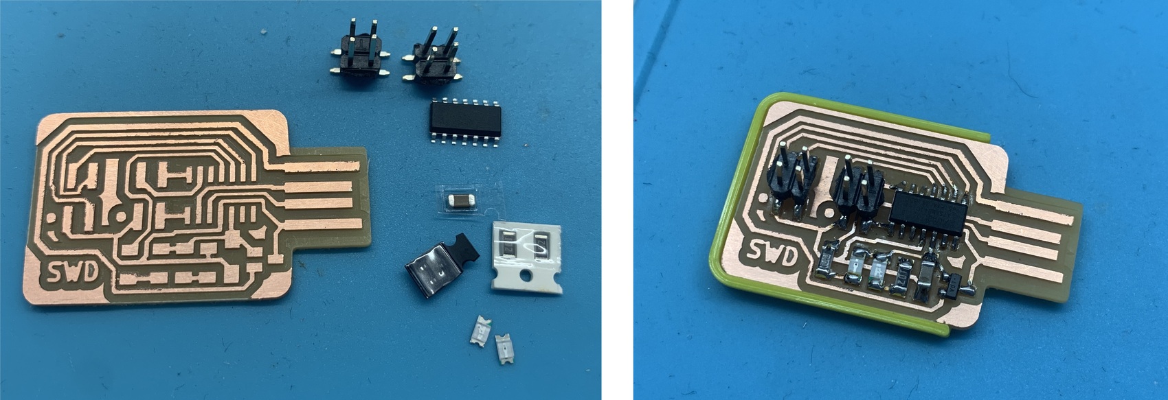
Here you can see the components.
Once the board is milled and welded. The 3D case can be found here.
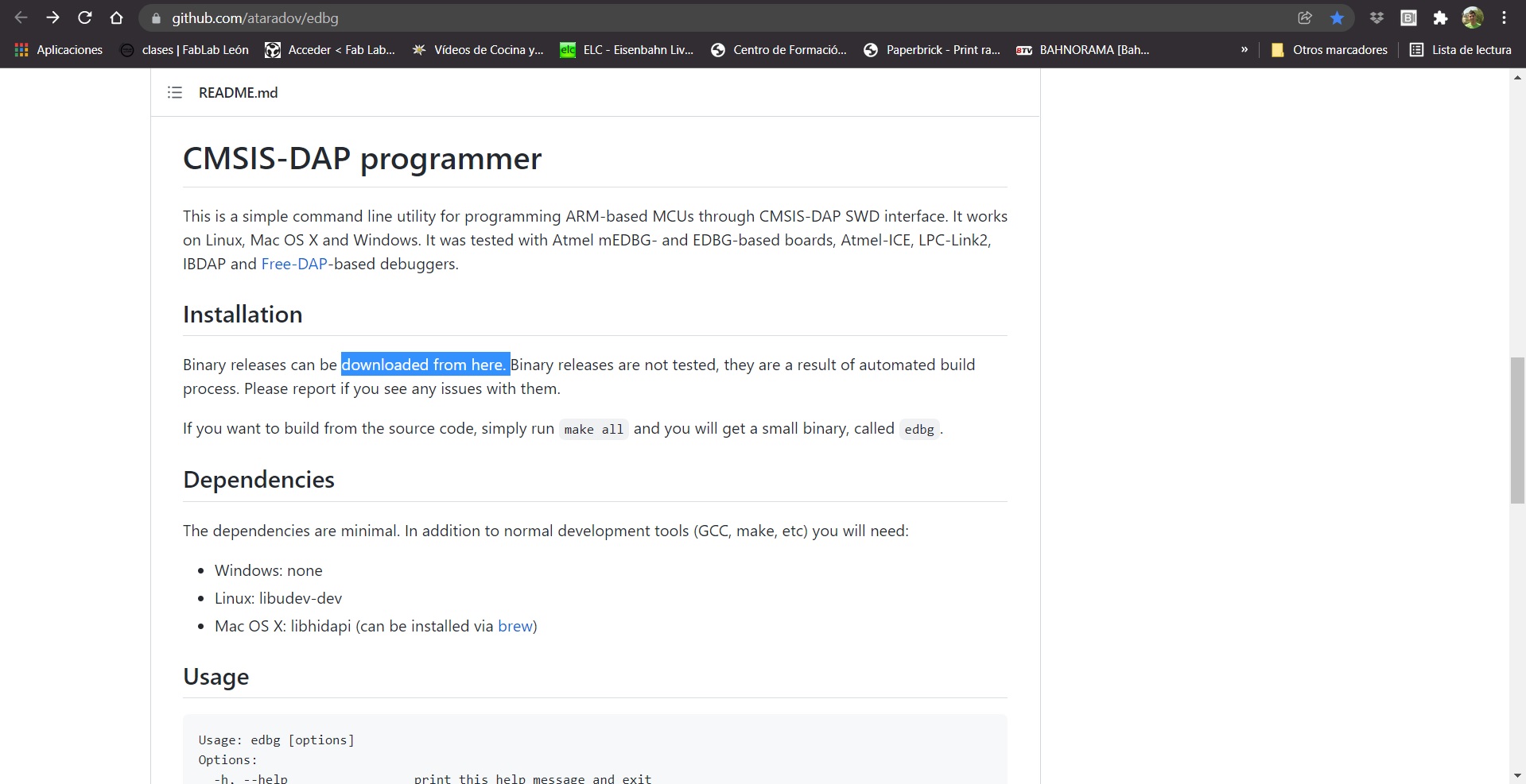
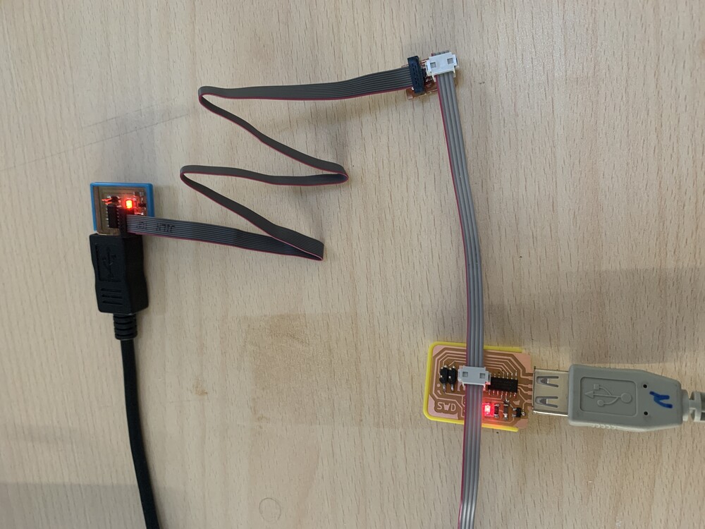
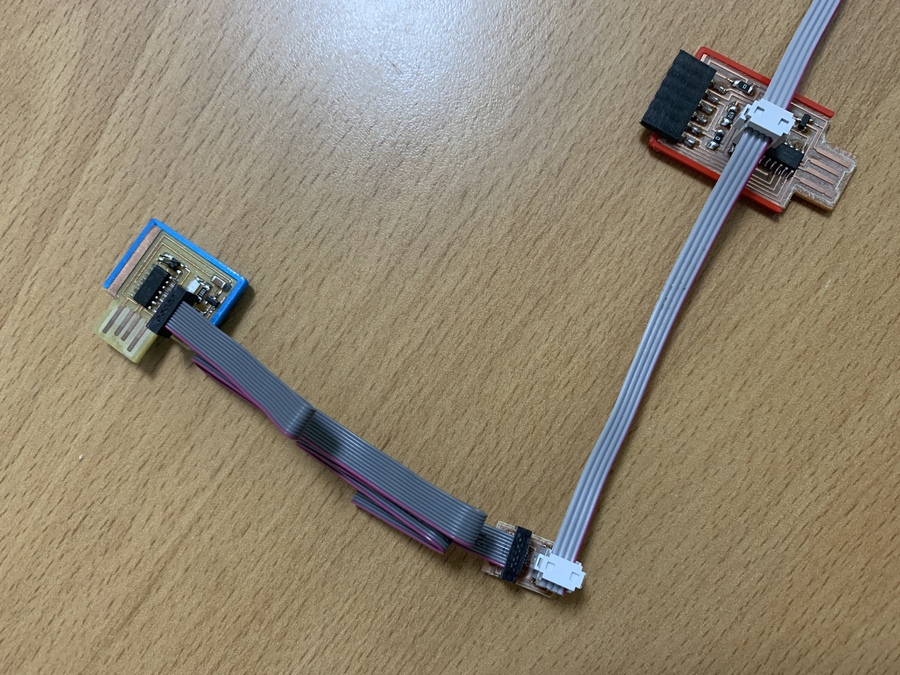
The next step is to program the new board. To do this, we connect our SAMD11C Free Dap Programmer as follows, carefully checking the 10-4 converter connections.
Next we load the Free Dap bootloader to work with Arduino. For this point you can follow this part of the documentation, in the Free Dap Programmer point.
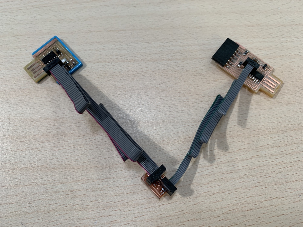
If we have another SWD Programmer, the connection to the new programmer will be as follows. A flat cable and two 4-pin female connectors will suffice.
SAMD11C Serial.
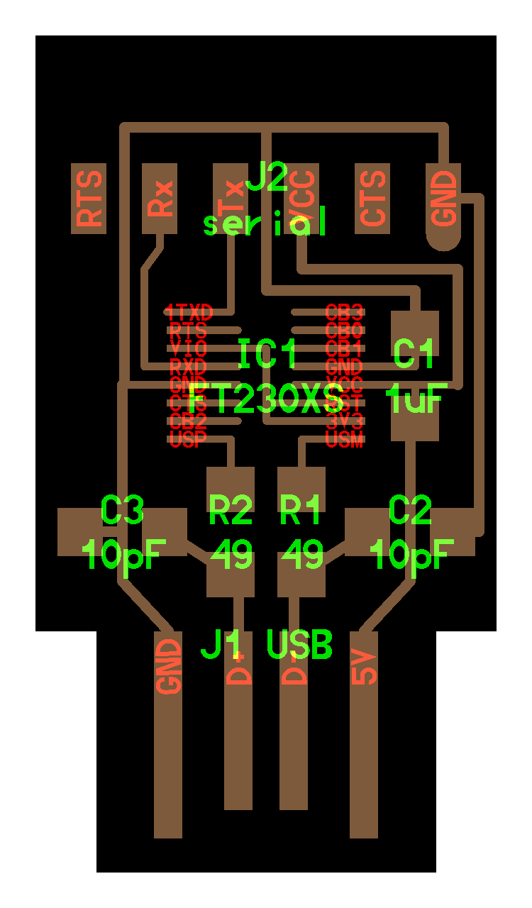
During the Fab Academy 2020 to read the Serial of different microcontrollers we used an FTDI, or the FT230XS (a complex chip to solder 😅). But Quentin Bolsee and Neil Gershenfeld developed a Serial reader through the SAMD11C.
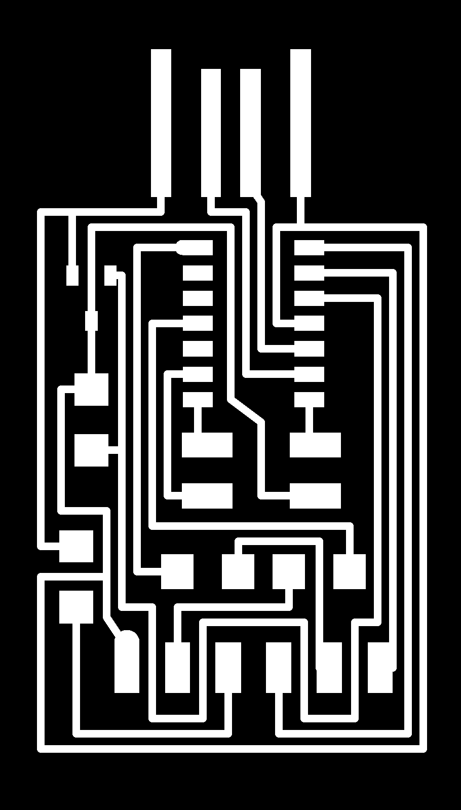
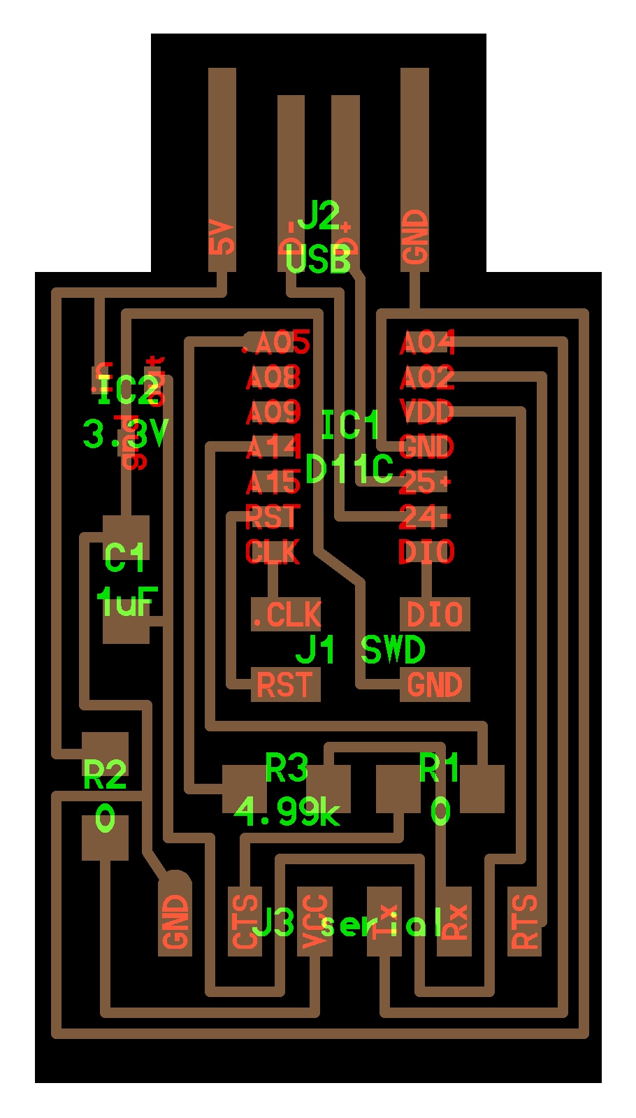
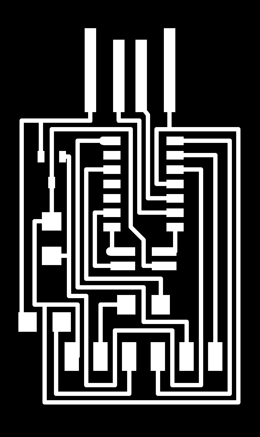
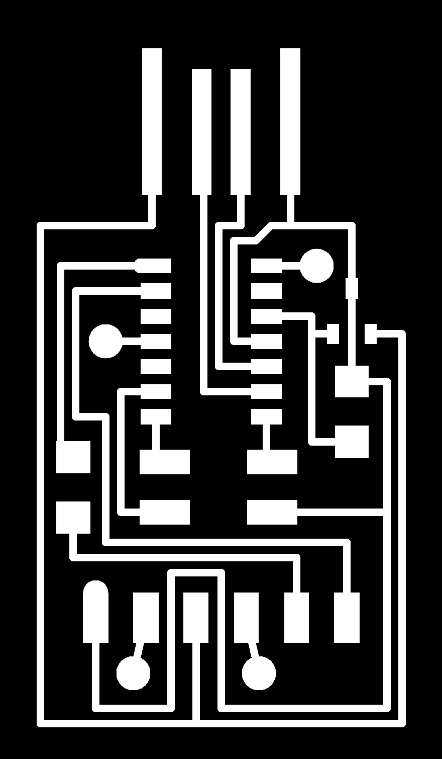
The first thing we will do is download the following PNG files to create the board. You can find them in the Embedded Programming assignment of the Fab Academy. (There are two versions, one for single-sided or double-sided boards). The V0 version was the first, it works but does not contain the 4.7K protection resistor for the RX as the V1 version does.
- SAMD11C Serial V1 traces
- SAMD11C Serial V1 interior
- SAMD11C Serial V1 components
- 10 to 4 pin converter traces.
- 10 to 4 pin converter interior.
- 10 to 4 pin converter components
SAMD11C Serial V0 traces (Obsolete)SAMD11C Serial V0 interior (Obsolete)- SAMD11C Serial V2 traces top
- SAMD11C Serial V2 traces bottom
- SAMD11C Serial V2 traces holes
- SAMD11C Serial V2 traces interior
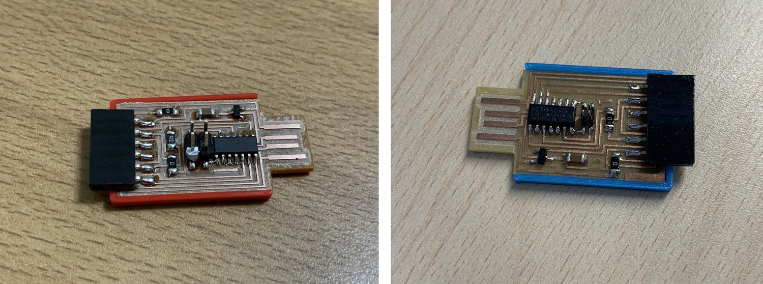
In my case, I make a single-sided board. Here the components
The milled board and components; all assembled.
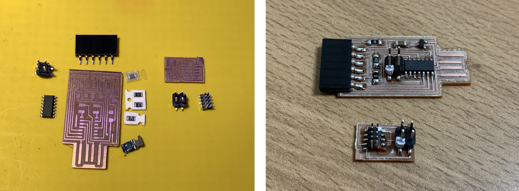
This is the V0 version, now obsolete.
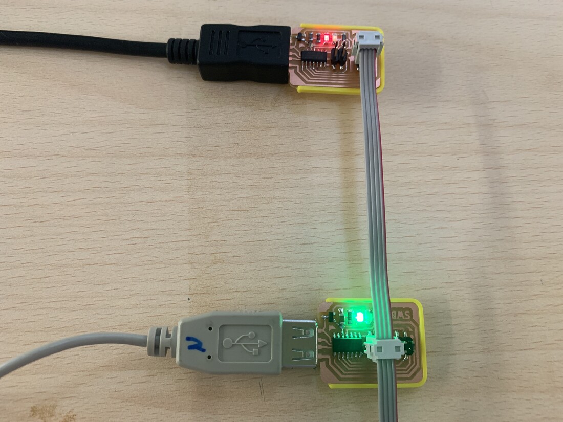
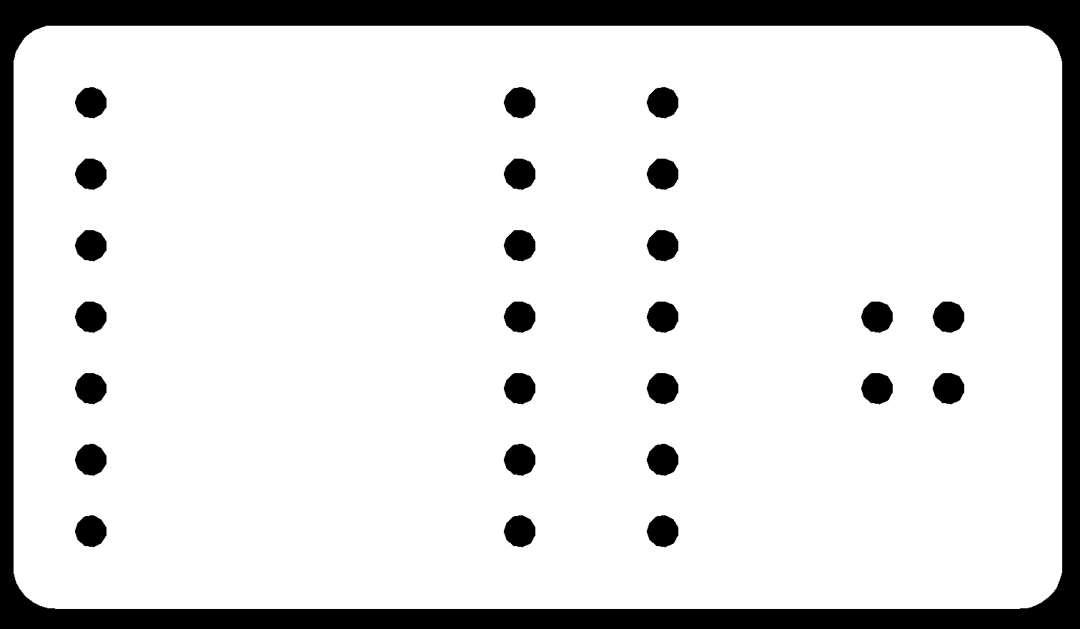
The next step is to program the new board. To do this, we connect our SAMD11C Free Dap Programmer as follows, carefully checking the 10 to 4 pin converter connections.
This is the V0 version, now obsolete.
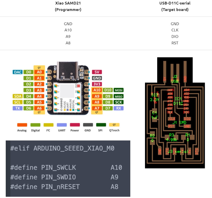
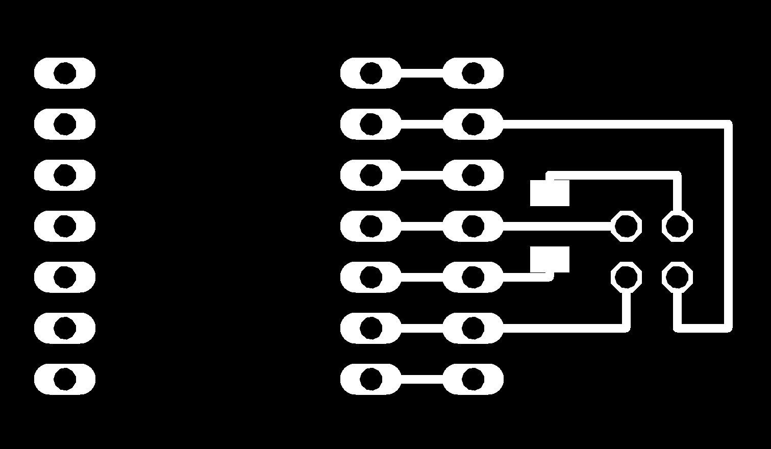
If you use the SAMD11C SWD, the connection is easier and you don't need a 10-4 pin converter. It would connect like this.
Next we load the sam_ba bootloader to work with Arduino. For this point you can follow this part of the documentation, in the Arduino point.
Once we have loaded the bootloader, we will follow the following Quentin Bolsee tutorial to load the Serial program for the SAMD11C.
To have a good contact on the USB, design a 3D case. We already have a programmer for the UPDI and a substitute for the FTDI to read the Serial. Here is the V0 version.
Burn bootloader with XIAO SAMD 21.
During the Bali Fab Fest, instructor Yuichi Tamiya from Fab Lab Kannai held a workshop to explain how to upload the bootloader to the SAMDs using the Xiao SAMD21 from Seeed Studio. Thank you Yuichi 🤗
To do this, you will find everything you need in the following documentation.
Several recommendations.
- Install the latest Arduino IDE 2.0.0 for this to work.
- Download the simple_daplink_xiao.uf2 files
- Package Seeeduino boards
- The connections.
Also Yuichi, designed a board to be able to connect the Xiao SAMD21 and load the bootloader to the SAMD's. Here are the designs.
The materials are pin headers and a 0 ohm resistor. When uploading the bootloader, remember to power the other board.
Programming Errors.
During the programming of the SAMD's, sometimes we can get a series of errors in the terminal that we do not understand. Many are errors of poor connection of the programmer or soldering failures of the new board. Like for example this one.
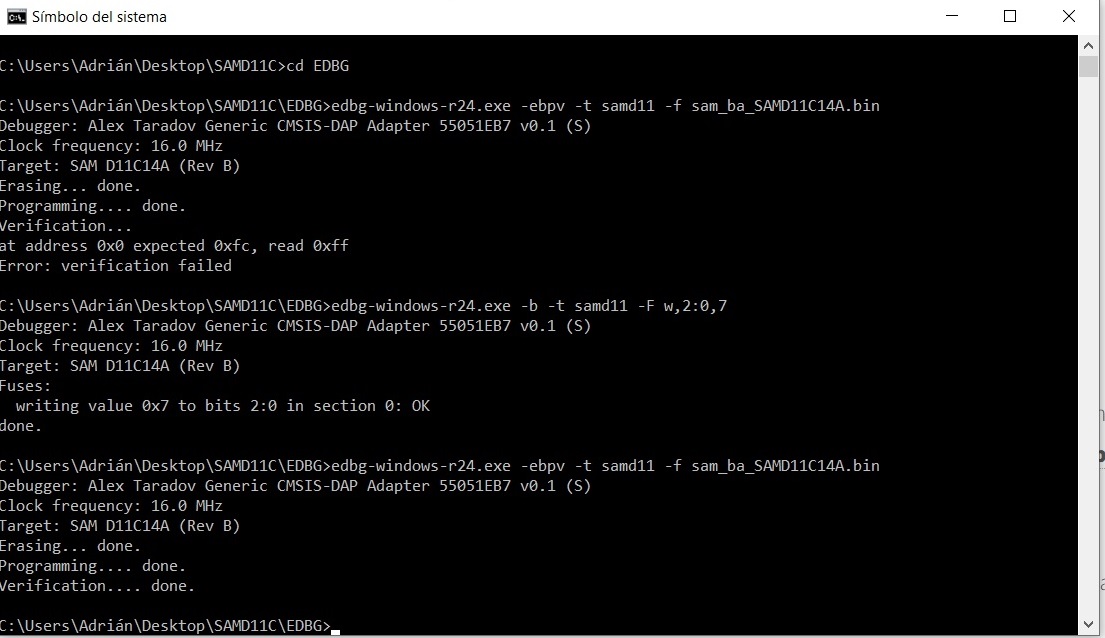
Another very strange may be this. A SAMD11C Serial, loaded several times with different bootloaders (free_dap or sam_ba) and at the time of verification the following error appears: at address 0x0 expected 0xfc, read 0xff. Error: verification failed
Thanks to Quentin and Neil who have already reported this bug. You have to perform the following command: edbg-windows-r24.exe -b -t target_type -F w,2:0,7
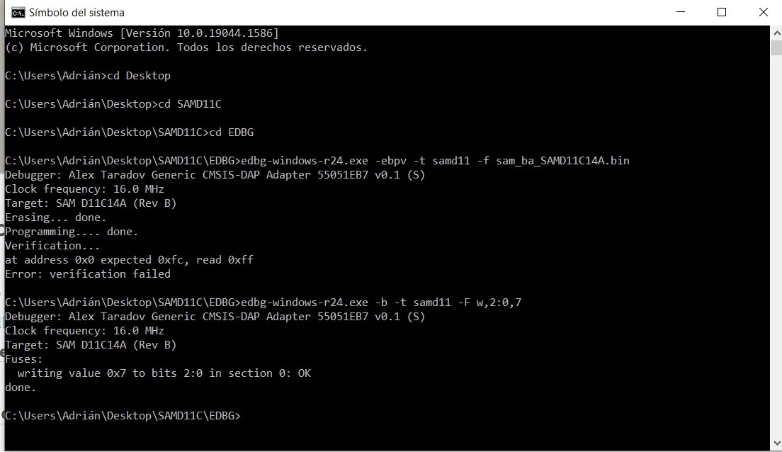
Finally, we load the sam_ba's boatloader and it works!
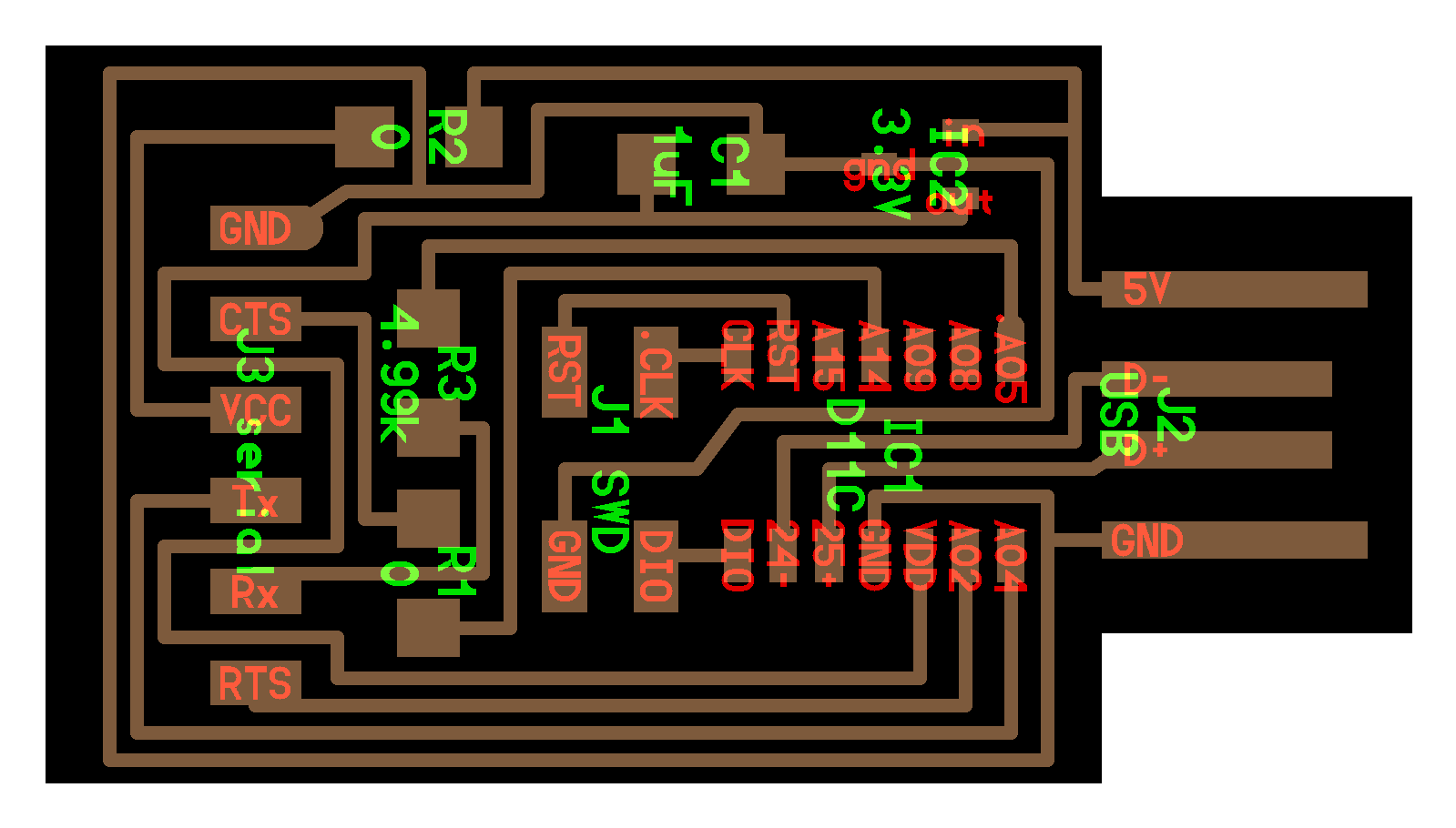
BOM and Schematic for SAMDino
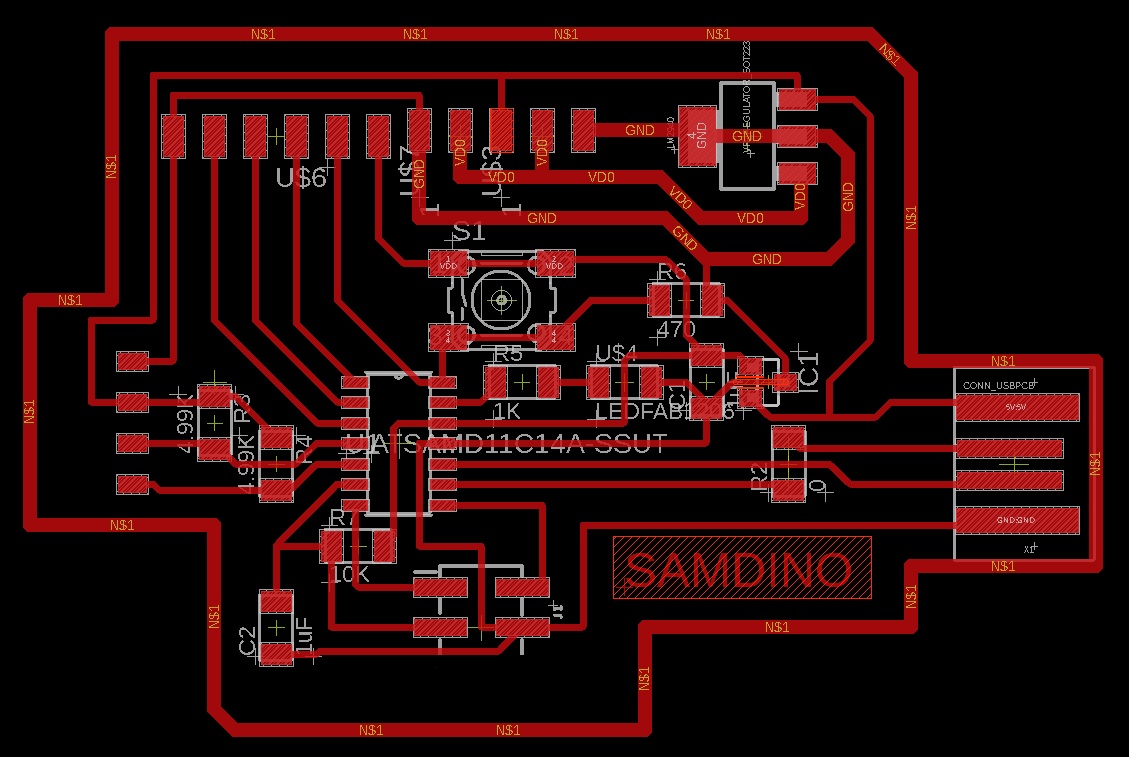
This is the schematic where you can see all the components.
Samdino |
Where to buy? | Amount | Price | Total price |
| Proto Board FR1 | Digikey | 1/4 board | 1,24 €/unit | 0,31 € |
| SAMD11C 14A | Digikey | 1 | 1,01 €/unit | 1,01 € |
| 1uF capacitor 50V | Digikey | 2 | 0,18 €/unit | 0,36 € |
| 4,99kΩ resistor | Digikey | 2 | 0,09 €/unit | 0,18 € |
| 499 Ω resistor | Digikey | 1 | 0,09 €/unit | 0,09 € |
| IC Regulator 5V 1A SOT223 | Digikey | 1 | 0,43 €/unit | 0,43 € |
| IC Regulator 3.3V 100MA SOT23-3 | Digikey | 1 | 0,84 €/unit | 0,84 € |
| 1kΩ resistor | Digikey | 1 | 0,09 €/unit | 0,09 € |
| 10kΩ resistor | Digikey | 1 | 0,62 €/unit | 0,62 € |
| LED | Digikey | 1 | 0,35 €/unit | 0,35 € |
| Button | Digikey | 1 | 1,00 €/unit | 1,00 € |
| Female 1 row horizontal header | Digikey | 14 | 0,15 €/unit | 2,10 € |
| Connector Header SMD 4POS 1.27mm | Digikey | 1 | 0,39 €/unit | 0,39 € |
| Total cost | 7,77 € |
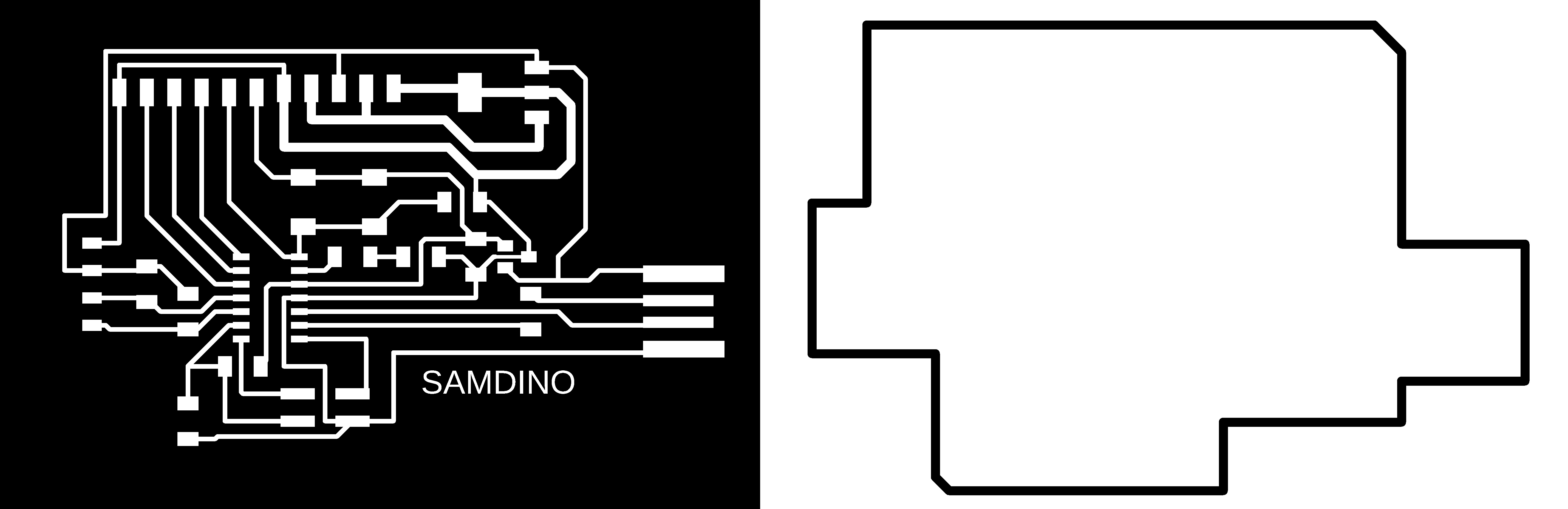
Board design
Here you can download the Eagle files and the PNG's. Here is a sample of the PNG's, traces and cutting lines.
Inputs
Button
The button is the simplest element of the inputs. It is an open or closed contact that when we press it changes its state to closed or open.
In this case, the button is integrated on the board, on the PA04 pin (Arduino pin 4) and the LED on the PA02 pin (Arduino pin 2).
Here you will find the programming to use the button. Here you can find the Arduino file to download.
//Fab Academy 2020 - Fab Lab León
//Button + LED
//SAMDino
//SAMD11C
//
//Original code:Neil Gershenfeld 12/8/19
// This work may be reproduced, modified, distributed,
// performed, and displayed for any purpose, but must
// acknowledge this project. Copyright is retained and
// must be preserved. The work is provided as is; no
// warranty is provided, and users accept all liability.
//


const int ledPin1 = 2;//first light
const int buttonPin = 4;// button pin
int buttonState = 0;//initial state of the button
int i = 0; //variable intensity led

void setup() { //declaration of inputs and outputs
  pinMode(ledPin1, OUTPUT);
  pinMode(buttonPin, INPUT);
}
void loop() {
  buttonState = digitalRead(buttonPin);// we read the state of the button
  if (buttonState == HIGH) { //if we press the button
  digitalWrite(ledPin1, HIGH);
  delay(500);
  digitalWrite(ledPin1, LOW);
  delay(500);
  digitalWrite(ledPin1, HIGH);
  delay(500);
  digitalWrite(ledPin1, LOW);
  delay(500);
  digitalWrite(ledPin1, HIGH);
  delay(2000);
  digitalWrite(ledPin1, LOW);
  delay(1000);

}
  else {  //if we don't press the button
  digitalWrite(ledPin1, LOW);
  }
}
Pyroelectric
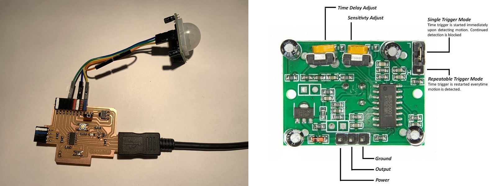
A passive infrared sensor (or PIR sensor) is an electronic sensor that measures infrared (IR) light radiated from objects in its field of view. They are mainly used in PIR-based motion detectors.
In this case we only need three cables; one for VCC to 5V, another for GND and another for the sensor output that in our case we will connect it to pin PA05 (5 in Arduino). I also use the LED that is on PA02 (Arduino pin 2).
Here you will find the programming to use a digital sensor such as the PIR. Here you can find the Arduino and Processing files to download.
//Fab Academy 2020 - Fab Lab León
//PIR sensor
//SAMDino
//SAMD11C

//Original code by Luis Llamas.

const int LEDPin = 2;        // for LED
const int PIRPin = 5;         // for PIR sensor

int pirState = LOW;           // start there is no movement
int val = 0;                  // pin status

void setup()
{
   pinMode(LEDPin, OUTPUT);
   pinMode(PIRPin, INPUT);
   Serial.begin(115200);
}

void loop()
{
   val = digitalRead(PIRPin);
   if (val == HIGH)   //if activated
   {
      digitalWrite(LEDPin, HIGH);  //LED ON
      if (pirState == LOW)
      {
        Serial.println("1");
        pirState = HIGH;
      }
   }
   else   //is not activated
   {
      digitalWrite(LEDPin, LOW); // LED OFF
      if (pirState == HIGH)  //si
      {
        Serial.println("0");
        pirState = LOW;
      }
   }
}
Doppler radar
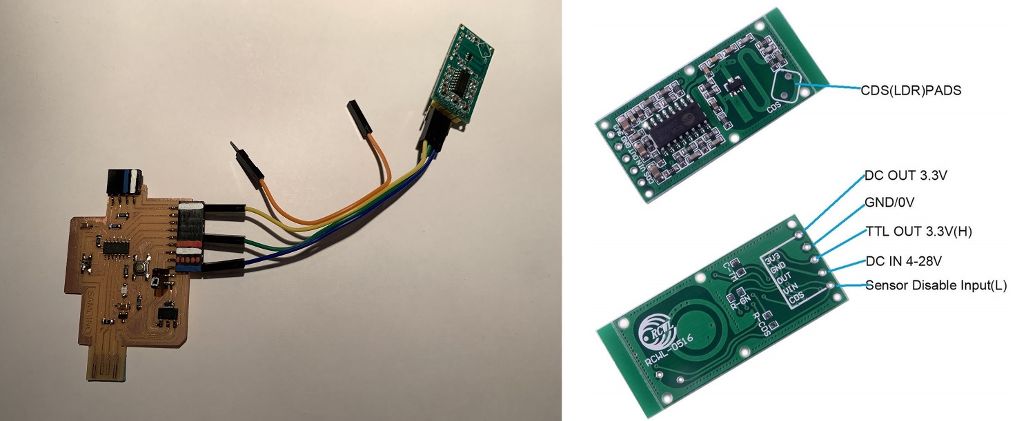
The RCWL-0516 is a Dopler Microwave Radar Sensor.It is an alternative to traditional PIR infrared motion detectors. Faced with these, it has certain differences, which will be an advantage or disadvantage depending on the needs of our project.
First of all, PIR sensors require the moving object to have a temperature difference from the environment. For this reason, they are able to detect people, but not moving objects. In contrast, the RCWL-0516 detects any object that is moving, regardless of its temperature. On the other hand, PIR sensors have sensitivity problems when the ambient temperature is high. The RCWL-0516, on the other hand, does not have this problem and works correctly between -20ºC to 80ºC. In terms of detection range, the RCWL-0516 has a greater range than PIR sensors, being able to easily reach 5-7 meters of range.
Finally, the RCWL-0516 is omnidirectional, that is, it detects movement in 360º. This is a difference from PIR sensors, which have a certain "angle of view". There are even versions of PIR with a narrow beam, for example to control windows or doors.
In this case we only need three cables; one for VCC, another for GND and another for the sensor output that in our case we will connect it to pin PA04 (4 in Arduino). IMPORTANT: connect the VCC to 5V.
Here you will find the programming to use a digital sensor such as the PIR. Here you can find the Arduino and Processing files to download.
//Fab Academy 2020 - Fab Lab León
//Doppler radar
//SAMDino
//SAMD11C


const int RadarPin = 4; // digital input pin to hook the sensor to
int value = 6; // variable to store the value coming from the sensor
void setup()
{
  Serial.begin(115200); // initialize serial communications
  pinMode(RadarPin, INPUT); //digital input pin
}

void loop()
{
  int value= digitalRead(RadarPin); // read the value from the sensor (0 or 1)
  Serial.println(value);  // print value to Serial Monitor
}
Ultrasonic sensor
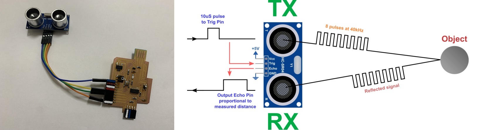
The HC-SR04 ultrasonic sensor uses sonar to determine distance to an object like bats do. It offers excellent non-contact range detection with high accuracy and stable readings in an easy-to-use package. It comes complete with ultrasonic transmitter and receiver modules.
In this case we only need four cables; one for VCC to 5V, one for GND, another cable for the Trigger (PA05, Arduino pin 5) and another for the Echo (PA04, Arduino pin 4).
Here you will find the programming to use a digital sensor such as the Ultrasonic sensor. Here you can find the Arduino and Processing files to download.
- Arduino Hello Ultrasonic sensor
- Processing Hello Ultrasonic sensor
//Fab Academy 2020 - Fab Lab León
//Ultrasonic sensor
//SAMDino
//SAMD11C


const int EchoPin = 4;
const int TriggerPin = 5;

void setup() {
   Serial.begin(115200);
   pinMode(TriggerPin, OUTPUT);
   pinMode(EchoPin, INPUT);
}

void loop() {
   int cm = ping(TriggerPin, EchoPin);
  Serial.print("");
   Serial.println(cm);
   delay(1000);
}

int ping(int TriggerPin, int EchoPin) {
   long duration, distanceCm;

   digitalWrite(TriggerPin, LOW);  //to generate a clean pulse we set LOW 4us
   delayMicroseconds(4);
   digitalWrite(TriggerPin, HIGH);  //we generate Trigger (trigger) of 10us
   delayMicroseconds(10);
   digitalWrite(TriggerPin, LOW);

   duration = pulseIn(EchoPin, HIGH);  //we measure the time between pulses, in microseconds

   distanceCm = duration * 10 / 292/ 2;   //we convert distance, in cm
   return distanceCm;
}
Hall effect
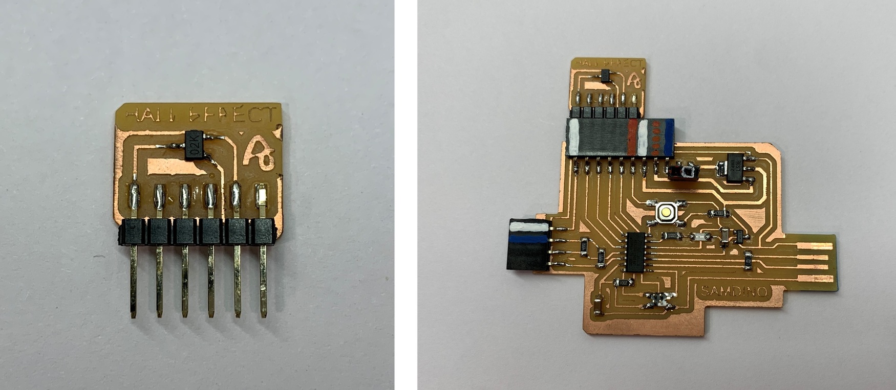
The Hall effect sensor or simply Hall sensor or Hall probe uses the Hall effect to measure magnetic fields or currents or to determine the position in which it is.
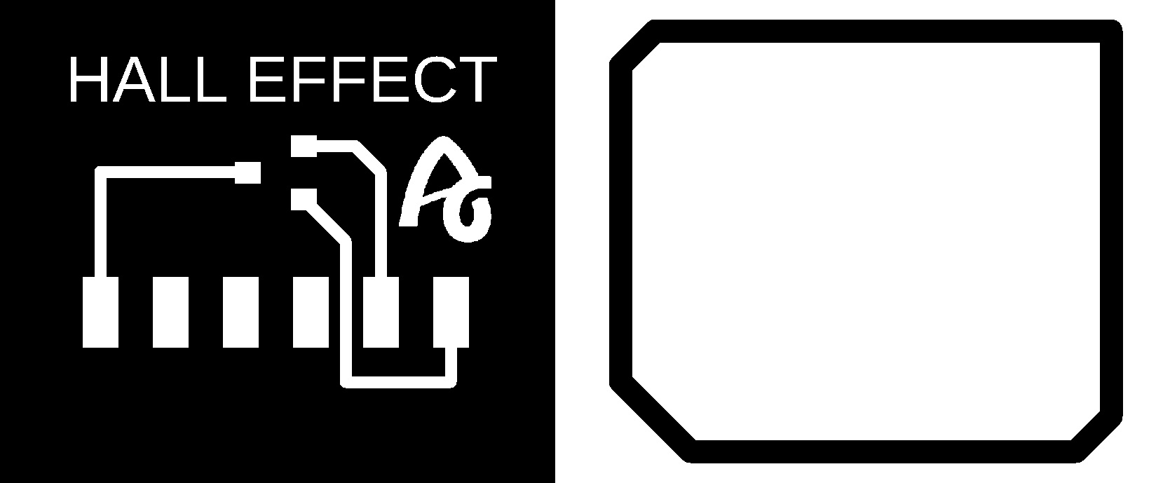
In this case, being a component without a module, I create my own. I design and manufacture a small board where I solder the hall effect sensor and with the flat connectors where there is no room for mistakes when connecting it. I use the analog input of the ATtiny1614 PA4 (Arduino pin 0).
Here you can find the design in Eagle and the PNG's to create the board.
- Hall effect Schematic + Board
Here you will find the programming to use an analog sensor such as the Hall effect sensor. Here you can find the Arduino and Processing files to download.
- Arduino Hello Hall effect sensor
- Processing Hello Hall effect sensor
//Fab Academy 2020 - Fab Lab León
//Hall Effect
//SAMDino
//SAMD11C

int sensorPin = 4;    // analog input pin to hook the sensor to
int sensorValue = 0;  // variable to store the value coming from the sensor

void setup() {
  Serial.begin(115200); // initialize serial communications
}

void loop() {
  sensorValue = analogRead(sensorPin); // read the value from the sensor
  sensorValue = map(sensorValue, 290, 300, 0, 1024);
  Serial.println(sensorValue); // print value to Serial Monitor
  //mySerial.println("x"); // print value "x" to Serial Monitor
  delay(500); // short delay so we can actually see the numbers
}
Temperature. NTC.
The NTC sensor is a type of resistance whose value varies as a function of temperature in a more pronounced way than a common resistance. Its operation is based on the variation of the resistivity that a semiconductor presents with temperature.
In this case, being a component without a module, I create my own. I design and manufacture a small board where I solder the NTC sensor, a 10K resistor and with the flat connectors where there is no room for mistakes when connecting it. I use the analog input of the SAMD11C PA04 (Arduino pin 4).
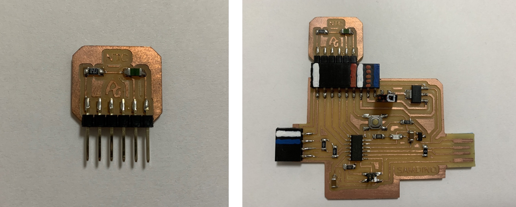
Here you can find the design in Eagle and the PNG's to create the board.
Here you will find the programming to use an analog sensor such as the NTC sensor. Here you can find the Arduino and Processing files to download.
- Arduino Hello NTC Temperature sensor
- Processing Hello NTC Temperature sensor
//Fab Academy 2020 - Fab Lab León
//NTC sensor
//SAMDino
//SAMD11C
int sensorPin = 4;    // analog input pin to hook the sensor to
int sensorValue = 0;  // variable to store the value coming from the sensor

void setup() {
  Serial.begin(115200); // initialize serial communications
}

void loop() {
  sensorValue = analogRead(sensorPin); // read the value from the sensor
  sensorValue = map(sensorValue, 0, 85, 0, 40);
  Serial.println(sensorValue); // print value to Serial Monitor
  //mySerial.println("x"); // print value "x" to Serial Monitor
  delay(500); // short delay so we can actually see the numbers
}
Phototransistor. Visible.
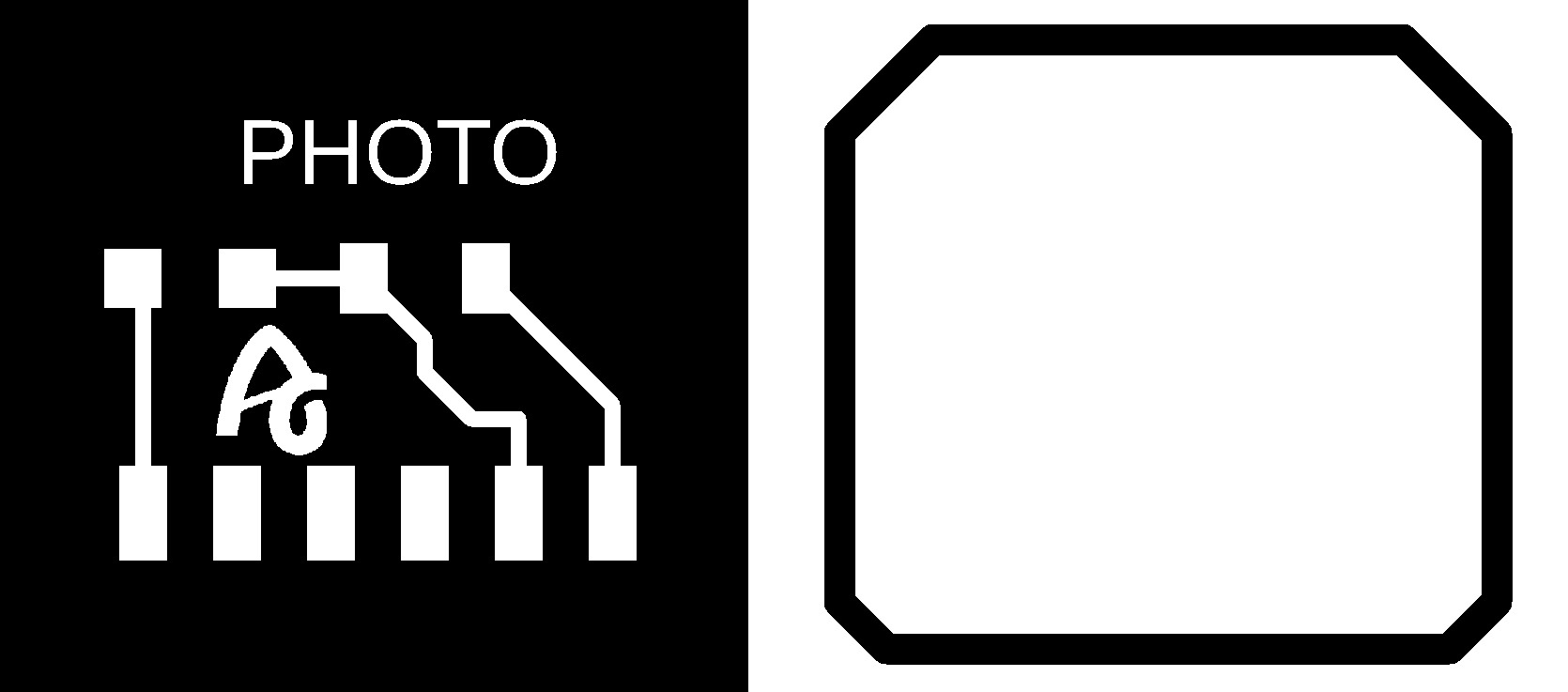
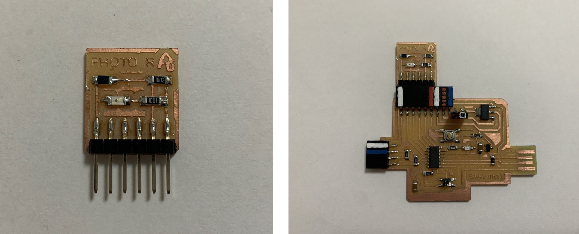
The Phototransistor sensor is a three-layer semiconductor device which has a light-sensitive base region. The base senses the light and converts it into the current which flows between the collector and the emitter region.
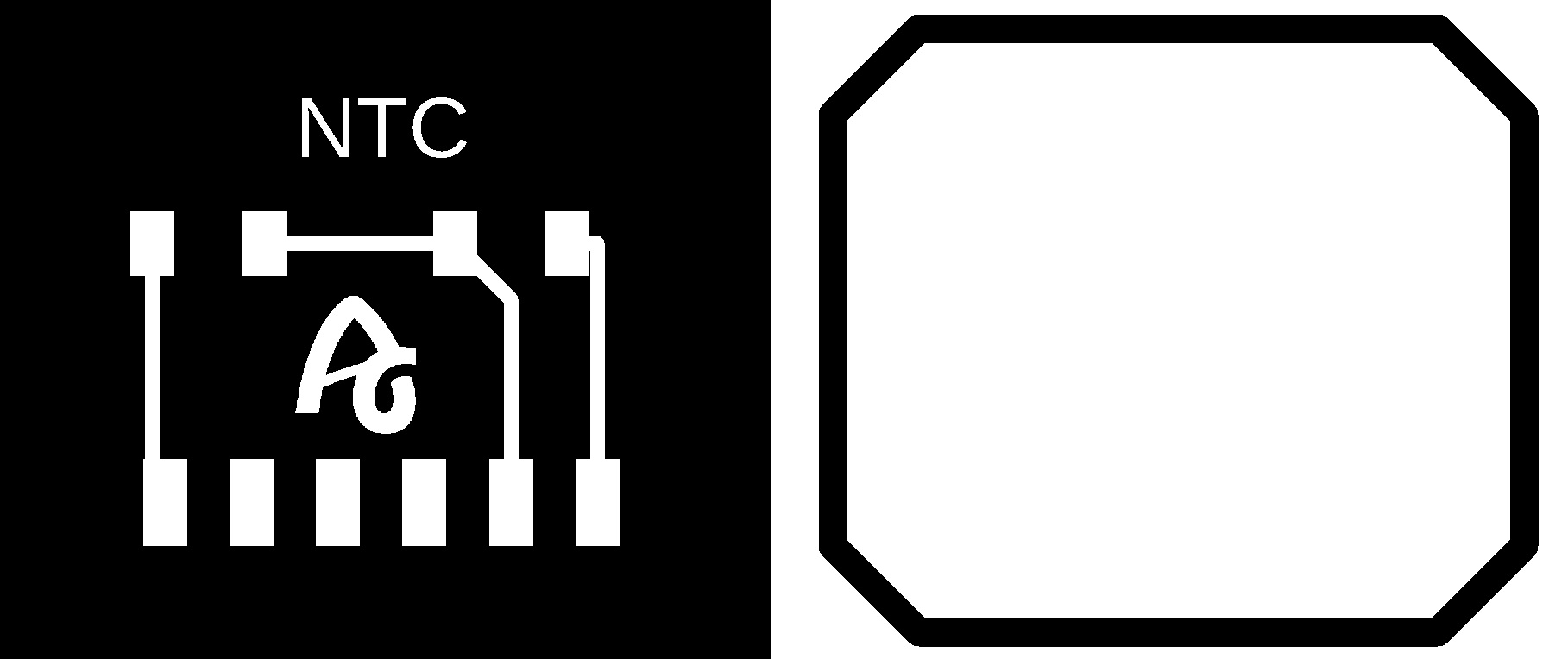
In this case, being a component without a module, I create my own. I design and manufacture a small board where I solder the Phototransistor sensor, a 10K resistor and with the flat connectors where there is no room for mistakes when connecting it. I use the analog input of the SAMD11C PA04 (Arduino pin 4).
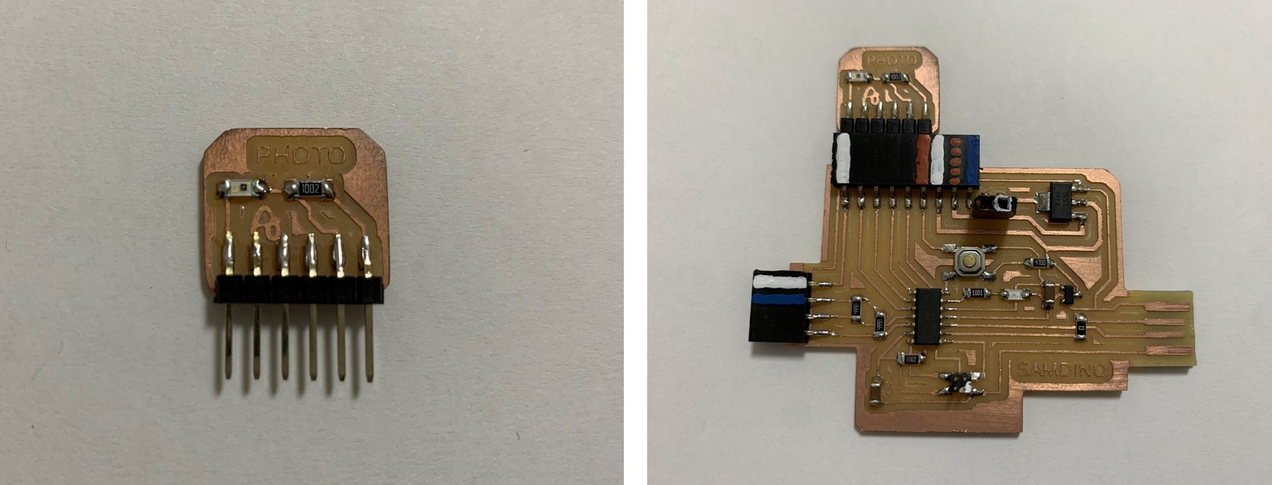
Here you can find the design in Eagle and the PNG's to create the board.
- Phototransistor Schematic + Board
Here you will find the programming to use an analog sensor such as the Phototransistor sensor. Here you can find the Arduino and Processing files to download.
- Arduino Hello Phototransistor sensor
- Processing Hello Phototransistor sensor
//Fab Academy 2020 - Fab Lab León
//Phototransistor
//SAMDino
//SAMD11C
int sensorPin = 4;    // analog input pin to hook the sensor to
int sensorValue = 0;  // variable to store the value coming from the sensor

void setup() {
  Serial.begin(115200); // initialize serial communications
}

void loop() {
  sensorValue = analogRead(sensorPin); // read the value from the sensor
  sensorValue = map(sensorValue, 25, 50, 0, 1024);
  Serial.println(sensorValue); // print value to Serial Monitor
  //mySerial.println("x"); // print value "x" to Serial Monitor
  delay(500); // short delay so we can actually see the numbers
}
Phototransistor. IR.
The Phototransistor IR sensor is a three-layer semiconductor device which has a light-sensitive base region. The base senses the IR and converts it into the current which flows between the collector and the emitter region.
In this case, being a component without a module, I create my own. I design and manufacture a small board where I solder the Phototransistor IR sensor, a 10K resistor, a IR LED, a 1K resistor and with the flat connectors where there is no room for mistakes when connecting it. I use the analog input of the SAMD11C PA04 (Arduino pin 4).
Here you can find the design in Eagle and the PNG's to create the board.
- Phototransistor IR Schematic + Board

Here you will find the programming to use an analog sensor such as the Phototransistor sensor. Here you can find the Arduino and Processing files to download.
- Arduino Hello Phototransistor IR sensor
- Processing Hello Phototransistor IR sensor
//Fab Academy 2020 - Fab Lab León
//Phototransistor IR
//SAMDino
//SAMD11C
int sensorPin = 4;    // analog input pin to hook the sensor to
int sensorValue = 0;  // variable to store the value coming from the sensor

void setup() {
  Serial.begin(115200); // initialize serial communications
}

void loop() {
  sensorValue = analogRead(sensorPin); // read the value from the sensor
  sensorValue = map(sensorValue, 40, 60, 0, 1024);
  Serial.println(sensorValue); // print value to Serial Monitor
  //mySerial.println("x"); // print value "x" to Serial Monitor
  delay(500); // short delay so we can actually see the numbers
}
Step Response.
The step-response is a sensor that is made with two sheets of copper, separated from each other by a porous insulating material. It can be used to calculate the value of force, weight, resistance ... I have followed Robert Hart's tutorial as well as Neil's examples.
A series of pulses is sent through the TX electrode, which, depending on the material between the two electrodes, allows more or less that series of pulses to pass. In the following graph you can see how it works. The other electrode will be connected between two resistors, one for pull-up and the other for pull-down and to an analog input.
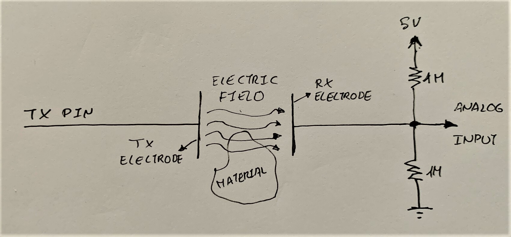
In this case, being a component without a module, I create my own. I design and manufacture a small board where I solder two 1M resistors and with flat connectors where there is no room for errors when connecting it. I use the analog input from the SAMD11C PA05 (Arduino pin 5) for the RX and a digital output from the SAMD11C PA08 (Arduino pin 8). Then with a connector there are two cables that connect the two electrodes (3M™ Copper Foil Tape).
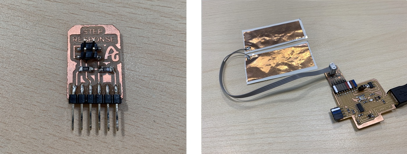
Here you can find the design in Eagle and the PNG's to create the board.
- Step Response Schematic + Board

Here you will find the programming to use a Step Response sensor. Here you can find the Arduino and Processing files to download. Below you can see a video of how it works.
- Processing Step Response TX/RX
//tx_rx03  Robert Hart Mar 2019.
//https://roberthart56.github.io/SCFAB/SC_lab/Sensors/tx_rx_sensors/index.html

//Modified by Adrián Torres Omaña
//Fab Academy 2021
//Step Response TX, RX
//SAMDino
//SAMD11C

//  Program to use transmit-receive across space between two conductors.
//  One conductor attached to digital pin, another to analog pin.
//
//  This program has a function "tx_rx() which returns the value in a long integer.
//
//  Optionally, two resistors (1 MOhm or greater) can be placed between 5V and GND, with
//  the signal connected between them so that the steady-state voltage is 2.5 Volts.
//
//  Signal varies with electric field coupling between conductors, and can
//  be used to measure many things related to position, overlap, and intervening material
//  between the two conductors.
//


long result;   //variable for the result of the tx_rx measurement.
int analog_pin = 5; //  PA05 of the SAMD11C
int tx_pin = 8;  //     PA08 of the SAMD11C
void setup() {
pinMode(tx_pin,OUTPUT);      //Pin 2 provides the voltage step
Serial.begin(115200);
}


long tx_rx(){         //Function to execute rx_tx algorithm and return a value
                      //that depends on coupling of two electrodes.
                      //Value returned is a long integer.
  int read_high;
  int read_low;
  int diff;
  long int sum;
  int N_samples = 100;    //Number of samples to take.  Larger number slows it down, but reduces scatter.

  sum = 0;

  for (int i = 0; i < N_samples; i++){
   digitalWrite(tx_pin,HIGH);              //Step the voltage high on conductor 1.
   read_high = analogRead(analog_pin);        //Measure response of conductor 2.
   delayMicroseconds(100);            //Delay to reach steady state.
   digitalWrite(tx_pin,LOW);               //Step the voltage to zero on conductor 1.
   read_low = analogRead(analog_pin);         //Measure response of conductor 2.
   diff = read_high - read_low;       //desired answer is the difference between high and low.
 sum += diff;                       //Sums up N_samples of these measurements.
 }
  return sum;
}                         //End of tx_rx function.


void loop() {

result = tx_rx();
result = map(result, -400, 2000, 0, 1024);  //I recommend mapping the values of the two copper plates, it will depend on their size
Serial.println(result);
delay(100);
}
This first video you can see how the two electrodes work with several sheets as intermediate material.
In this second video you can see how it works with a sponge as an intermediate material.
Outputs
RGB LED
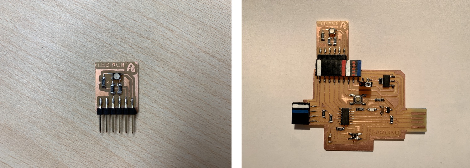
The RGB LED stands for Red, Blue and Green LEDs. RGB LED products combine these three colors to produce more than 16 million shades of light.
In this case, being a component without a module, I create my own. I design and manufacture a small board where I solder the RGB LED, two 1K resistors (for red and green color), a 499 resistor (for blue color) and with the flat connectors where there is no room for mistakes when connecting it. I use the digitals ouputs of the SAMDino PA04 (Arduino pin 4), PA05 (Arduino pin 5), PA08 (Arduino pin 8).
Here you can find the design in Eagle and the PNG's to create the board.
Here you will find the programming to use a RGB LED. Here you can find the Arduino file to download.
//Fab Academy 2020 - Fab Lab León
//RGB LED
//SAMDino
//SAMD11C

  const byte COLOR_BLACK = 0b000;
  const byte COLOR_BLUE = 0b100;
  const byte COLOR_RED = 0b010;
  const byte COLOR_GREEN = 0b001;
  const byte COLOR_MAGENTA = 0b101;
  const byte COLOR_CYAN = 0b011;
  const byte COLOR_YELLOW = 0b110;
  const byte COLOR_WHITE = 0b111;


  const byte PIN_LED_R = 5;
  const byte PIN_LED_G = 8;
  const byte PIN_LED_B = 4;


  void setup() {

    pinMode(PIN_LED_R, OUTPUT);
    pinMode(PIN_LED_G, OUTPUT);
    pinMode(PIN_LED_B, OUTPUT);
    displayColor(COLOR_BLACK);
  }


  void loop() {


    displayColor(COLOR_RED);
    delay(1000);

    displayColor(COLOR_GREEN);
    delay(1000);

    displayColor(COLOR_BLUE);
    delay(1000);

    displayColor(COLOR_MAGENTA);
    delay(1000);

    displayColor(COLOR_CYAN);
    delay(1000);

    displayColor(COLOR_YELLOW);
    delay(1000);

    displayColor(COLOR_WHITE);
    delay(1000);

    displayColor(COLOR_BLACK);
    delay(1000);

  }

  void displayColor(byte color) {

    digitalWrite(PIN_LED_R, !bitRead(color, 0));
    digitalWrite(PIN_LED_G, !bitRead(color, 2));
    digitalWrite(PIN_LED_B, !bitRead(color, 1));
  }
DC Motor
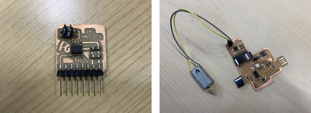
To control a DC motor we will use an H bridge, such as the Allegro A4953. With this driver we can control all types of motors through PWM signals.
In this case, being a component without a module, I create my own. I design and manufacture a small board where I solder the Allegro A4953 driver, a 1uF capacitor, a 10uF capacitor and with the flat connectors where there is no room for mistakes when connecting it. It includes two traces to feed with the 9V battery. I use two digital output of the SAMD11C PA04 (Arduino pin 4) and PA05 (Arduino pin 5).
Here you can find the design in Eagle and the PNG's to create the board.

Here you can find an example of a motor turning left, stopping, and turning right. Here you can find the Arduino file to download.
//Fab Academy 2020 - Fab Lab León
//Motor
//SAMDino
//SAMD11C

const int motor1Pin = 4;      // H-bridge pin 0 (in2)
const int motor2Pin = 5;      // H-bridge pin 1 (in1)

void setup() {

    // set H-bridge pins as outputs:
    pinMode(motor1Pin, OUTPUT);
    pinMode(motor2Pin, OUTPUT);
  }

void loop() {
   // change the direction the motor spins by talking to the control pins
  // on the H-Bridge

    digitalWrite(motor1Pin, HIGH);    // Turn the motor in one direction
    digitalWrite(motor2Pin, LOW);

    delay(2000);                      // Wait two seconds

    digitalWrite(motor1Pin, LOW);     // Switch off the motor
    digitalWrite(motor2Pin, LOW);

    delay(3000);                      // Wait three seconds

    digitalWrite(motor1Pin, LOW);
    digitalWrite(motor2Pin, HIGH);    // Turn the motor in the other direction


    delay(2000);                      // Wait two seconds

    digitalWrite(motor1Pin, LOW);     // Switch off the motor
    digitalWrite(motor2Pin, LOW);

    delay(3000);                      // Wait three seconds
  }
Servo motor
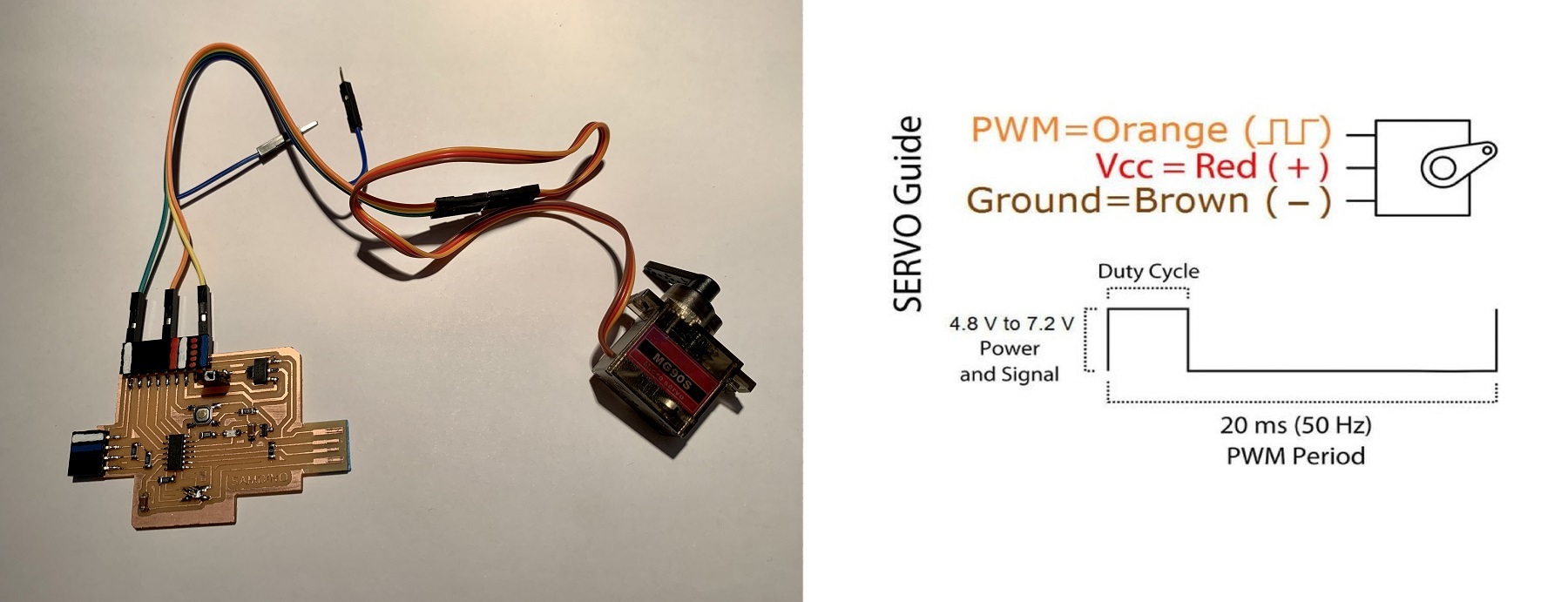
A very common output is a servo. A servomotor is a device similar to a direct current motor that has the ability to be located in any position within its operating range, and remain stable in that position. In this case I use a 0 to 180 degree servo.
In this case we only need three cables; one for VCC, another for GND and another for the signal output that in our case we will connect it to pin PA04 (4 in Arduino). IMPORTANT: We must supply the servo with 5V. The circuit can be powered by a 9V battery.
Here you will find the programming to use a servo motor. Here you can find the Arduino file to download.
//Fab Academy 2020 - Fab Lab León
//Servo without library
//SAMDino
//SAMD11C


int servo = 4;

int angle;
int pwm;

void setup()
{
 pinMode(servo, OUTPUT);
}

void loop ()
{
 for (angle = 0; angle <= 140; angle += 5)  {
   servoPulse(servo, angle);  }
 for (angle = 140; angle >= 0; angle -= 5)  {
   servoPulse(servo, angle);  }
}

void servoPulse (int servo, int angle)
{
 pwm = (angle*11) + 500;      // Convert angle to microseconds
 digitalWrite(servo, HIGH);
 delayMicroseconds(pwm);
 digitalWrite(servo, LOW);
 delay(50);                   // Refresh cycle of servo
}
Files
Find below the files that I made for this project.