
Index
Introduction
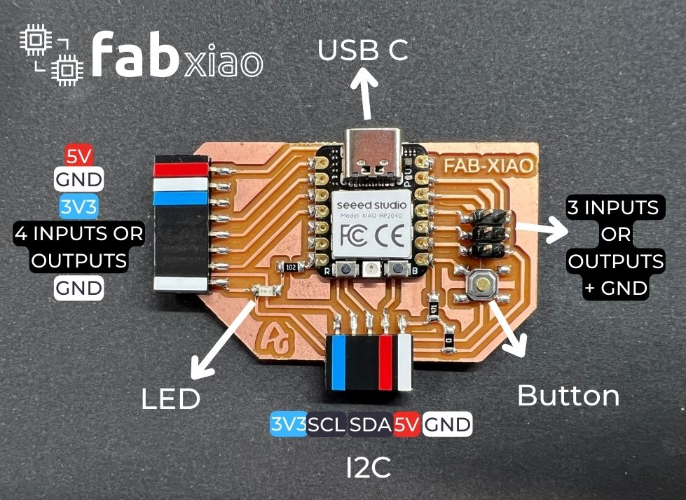
During the Instructor Bootcamp in Amsterdam, Neil recommended starting with the Seeed Studio Xiao, specifically the RP2040 model or the ESP32C3. In my case, this Fab-Xiao uses the Seeed Studio Xiao RP2040 model. The Fab-Xiao can also use the Seeed Studio Xiao ESP32-C3.
For this I want to document the process of creating a dev board and several examples of inputs and outputs with this board. The idea is also to use Adrianino input and output modules.
Features
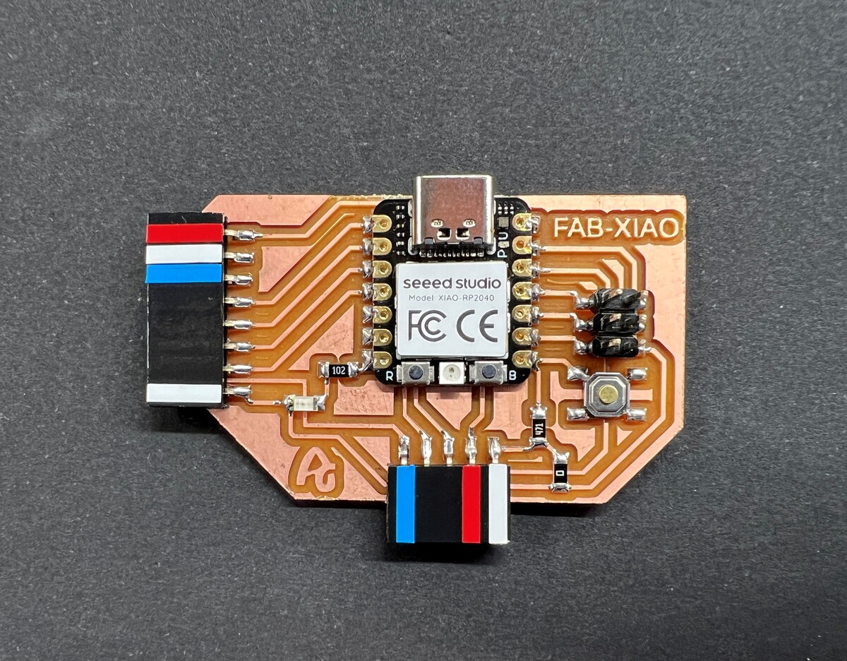
- Identification of the power supply pins 5V in red, 3V3 in blue and GND in white.
- On the left there are 4 outputs or inputs with VCC and GND on each side to be able to connect different inputs or outputs.
- On the right there are 3 outputs or inputs at the bottom and with a GND pinout.
- On the bottom there is an I2C connection to connect an LCD, OLED or a sensor that uses this communication.
- There is an LED and an integrated button, which will help us to test that the XIAO RP2040 works with a simple program.
- Possibility of connection with the Adrianino input and output modules.
Datasheet Seeed Studio XIAO RP2040
Seeed Studio XIAO RP2040 is compatible with the Raspberry Pi RP2040 ecosystem as they share the same RP2040 chip. It supports multiple languages including C / MicroPython / CircuitPython. This will be a great tool for you to get started with MicroPython.
- Powerful MCU: Dual-core ARM Cortex M0+ processor, flexible clock running up to 133 MHz.
- Rich on-chip resources: 264KB of SRAM, and 2MB of on-board Flash memory
- Flexible compatibility: Support Micropython/Arduino/CircuitPython
- Easy project operation: Breadboard-friendly & SMD design, no components on the back
- Small size: As small as a thumb(20x17.5mm) for wearable devices and small projects.
- Multiple interfaces: 11 digital pins, 4 analog pins, 11 PWM Pins,1 I2C interface, 1 UART interface, 1 SPI interface, 1 SWD Bonding pad interface.
For general I/O pins: Working voltage of MCU is 3.3V. Voltage input connected to general I/O pins may cause chip damage if it' higher than 3.3V . For power supply pins: The built-in DC-DC converter circuit able to change 5V voltage into 3.3V allows to power the device with a 5V supply via VIN-PIN and 5V-PIN. Please pay attention to use, do not lift the shield cover.
After looking at the basic features, you will find the pinning of the XIAO RP2040. More information in this link. Here the Seeed Studio XIAO RP2040 pinout sheet.
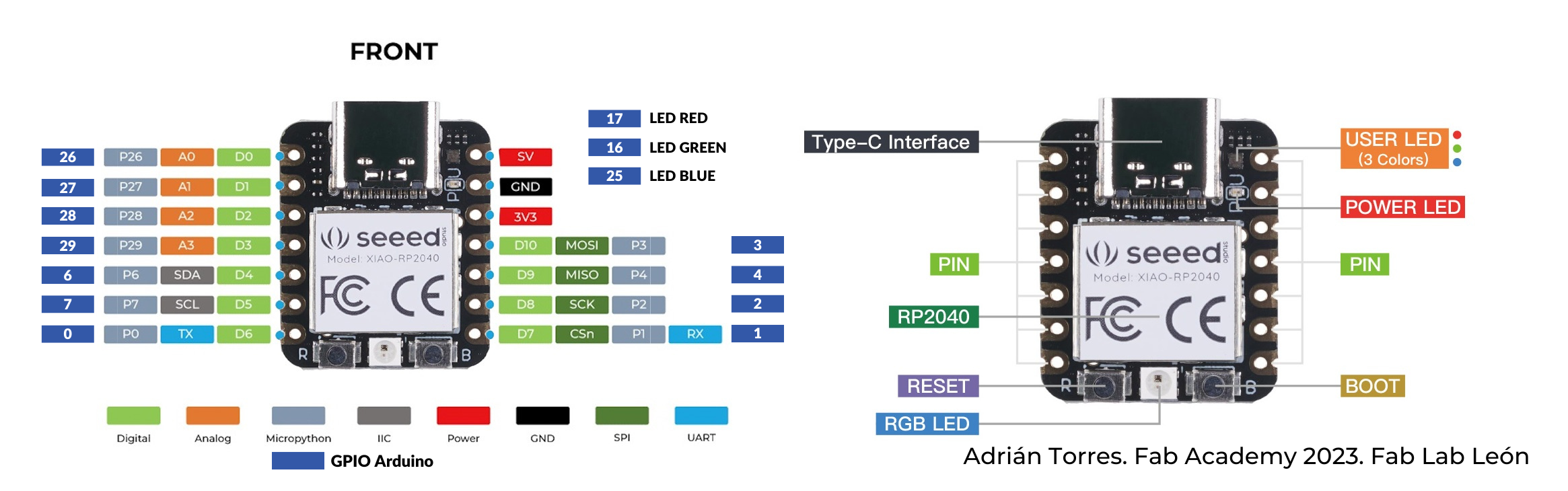
- 5V: Supply voltage 5V.
- GND: Ground.
- 3V3: Supply voltage 3V3.
- Digital pins (GPIO Pin number): 0, 1, 2, 3, 4, 6, 7, 26, 27, 28, 29
- Analog pins (GPIO Pin number): 26, 27, 28, 29
- LED Green (GPIO Pin number): 16
- LED Red (GPIO Pin number): 17
- LED Blue (GPIO Pin number): 25
- SDA (GPIO Pin number): 6
- SCL (GPIO Pin number): 7
- RGB LED_POWER (GPIO Pin number): 11
- RGB LED (GPIO Pin number): 12
Datasheet Seeed Studio XIAO ESP32-C3
Seeed Studio XIAO ESP32-C3 is an IoT mini development board based on the Espressif ESP32-C3 WiFi/Bluetooth dual-mode chip.
- Powerful CPU: ESP32-C3, 32 bit RISC-V single core processor that operates at up to 160 MHz
- Complete WiFi subsystem: Complies with IEEE 802.11b/g/n protocol and supports Station mode, SoftAP mode, SoftAP + Station mode, and promiscuous mode
- Bluetooth LE subsystem: Supports features of Bluetooth 5 and Bluetooth mesh
- Ultra-Low Power: Deep sleep power consumption is about 43μA
- Better RF performance: External RF antenna included
- Battery charging chip: Supports lithium battery charge and discharge management
- Rich on-chip resources: 400KB of SRAM, and 4MB of on-board flash memory
- Rich interfaces: 1xI2C, 1xSPI, 1xI2S, 2xUART, 11xGPIO(PWM), 4xADC, 1xJTAG bonding pad interface
For general I/O pins: This is 5v out from the USB port. You can also use this as a voltage input but you must have some sort of diode (schottky, signal, power) between your external power source and this pin with anode to battery, cathode to 5V pin. Working voltage of MCU is 3.3V.
After looking at the basic features, you will find the pinning of the XIAO ESP32-C3. More information in this link. Here the Seeed Studio XIAO ESP32-C3 pinout sheet.
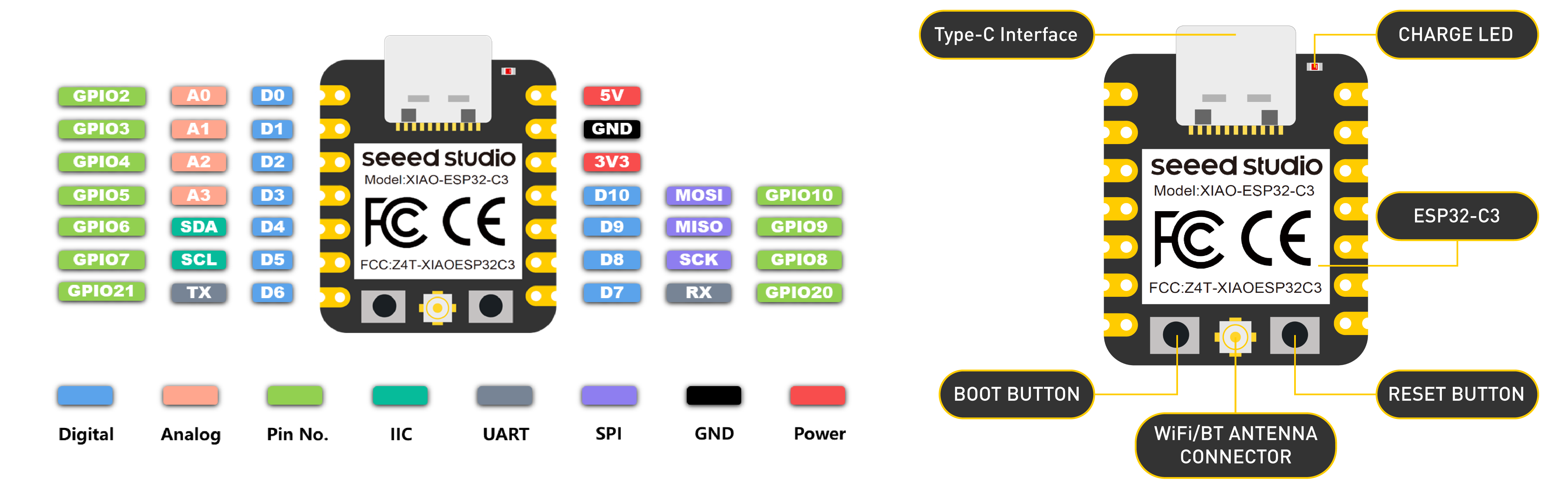
- 5V: Supply voltage 5V.
- GND: Ground.
- 3V3: Supply voltage 3V3.
- Digital pins (GPIO Pin number): D0, D1, D2, D3, D4, D5, D6, D7, D8, D9, D10, D11
- Analog pins (GPIO Pin number): A0, A1, A2, A3
- SDA (GPIO Pin number): D4
- SCL (GPIO Pin number): D5
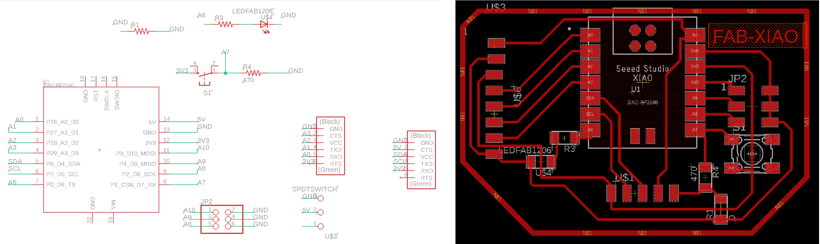
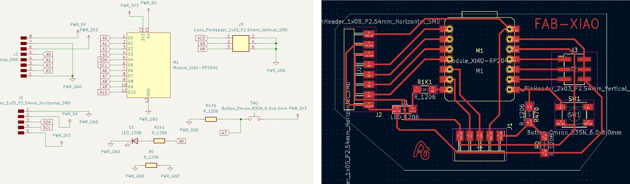
BOM and Schematic for Fab-Xiao
This is the schematic where you can see all the components.
Fab XIAO |
Where to buy? | Amount | Price | Total price |
| Proto Board FR1 | Digikey | 1/4 board | 1,24 €/unit | 0,31 € |
| Seeed Studio XIAO RP2040 | Seeed Studio | 1 | 5,00 €/unit | 5,00 € |
| 0Ω resistor | Digikey | 1 | 0,09 €/unit | 0,09 € |
| 499 Ω resistor | Digikey | 1 | 0,09 €/unit | 0,09 € |
| 1kΩ resistor | Digikey | 1 | 0,09 €/unit | 0,09 € |
| LED | Digikey | 1 | 0,35 €/unit | 0,35 € |
| Button | Digikey | 1 | 1,00 €/unit | 1,00 € |
| Female 1 row horizontal header | Digikey | 3 | 0,15 €/unit | 0,45 € |
| Male 2 row vertical header | Digikey | 1 | 0,65 €/unit | 0,65 € |
| Total cost | 8,03 € |
Board design
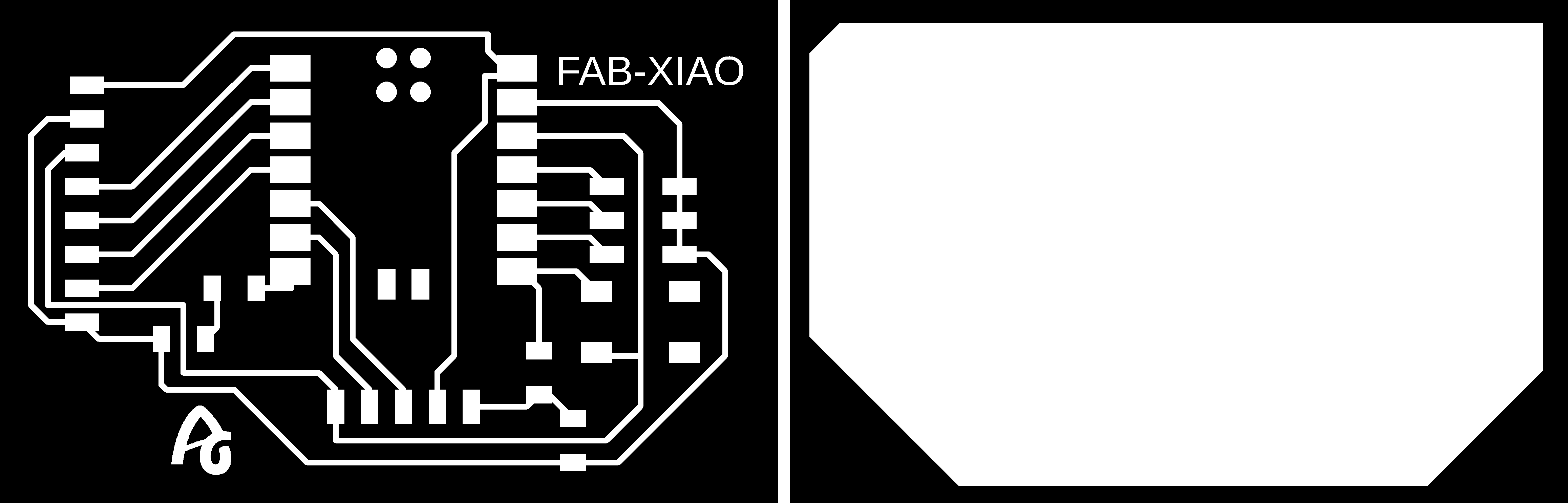
Here you can download the Eagle files and the PNG's. Here is a sample of the PNG's, traces and cutting lines. Here you can also find the library to add to your Eagle or kiCAD the traces of the Seeed Xiao RP2040 or ESP32-C3.
- Fab-Xiao Schematic + Board
- Fab-Xiao Traces
- Fab-Xiao Interior
- Seeed Xiao RP2040 and ESP32-C3 Eagle Library
- Fab Library for KiCAD with Seeed Xiao RP2040 and ESP32-C3
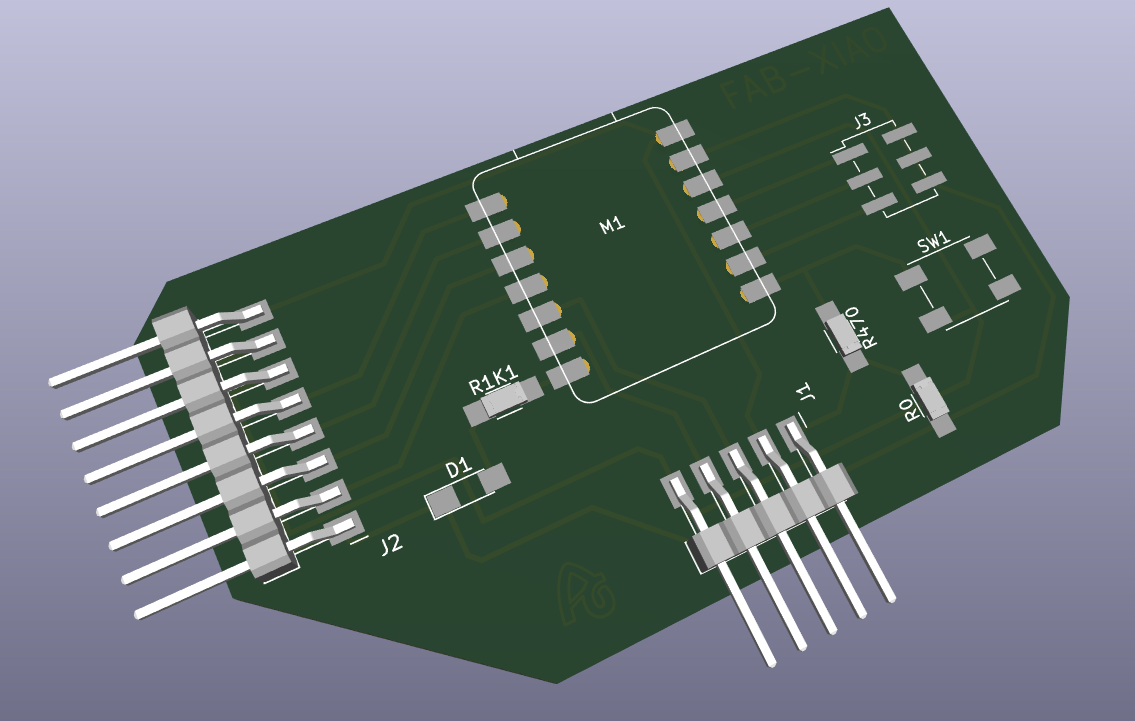
Here you can download the KICAD 6 files and the SVG's. You can also see a 3D simulation of the board.
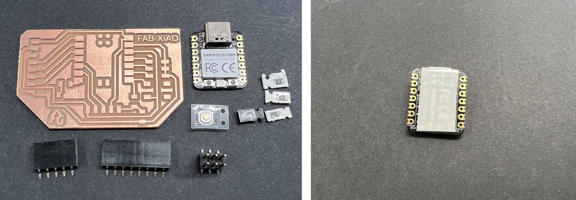
As the XIAO RP2040 has connection areas below and to avoid short circuits, I cover the bottom with 3M™ Epoxy Film Electrical Tape 1.
Programming. Seeed Studio XIAO RP2040 with Arduino
- 1. We open the Arduino program.
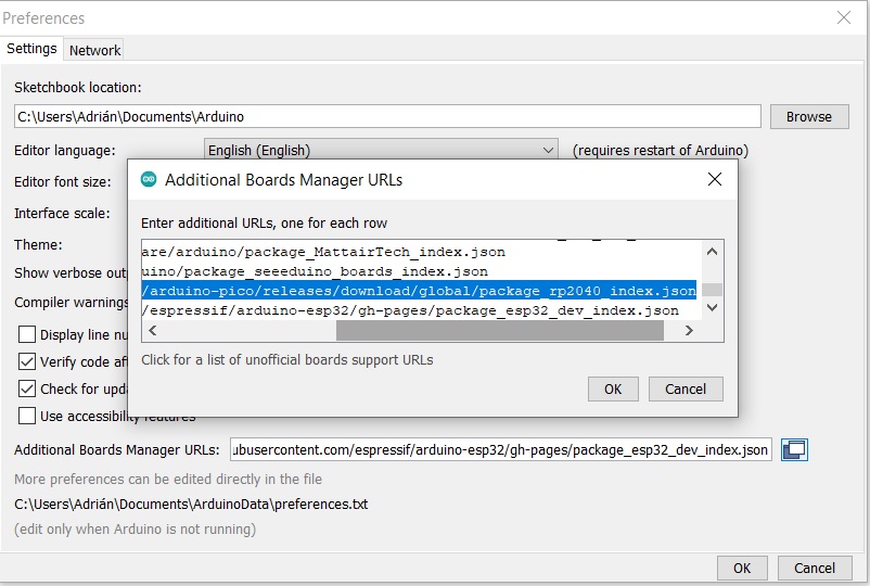
- 2. In Preferences, we will add the URL of the additional boards that you can find here. We need the Arduino-Pico by Earlephilhower
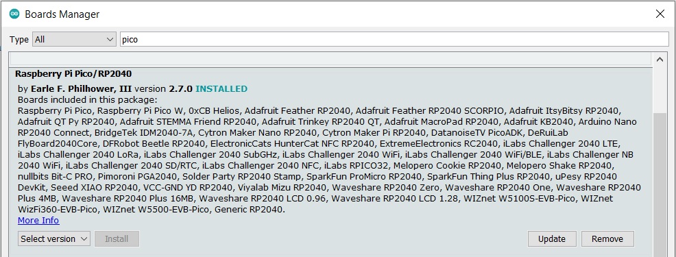
- 3. The next step is to download Pico in the boards manager.
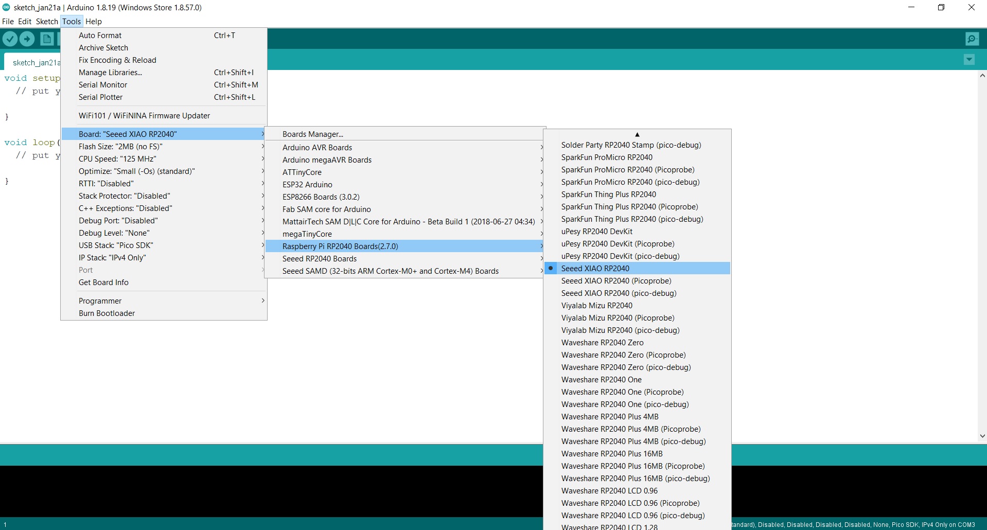
- 4. We configure the Arduino IDE for the Seeed Studio XIAO RP2040. The Seeed Studio XIAO RP2040 will appear in the COM port, in my case in COM 3.
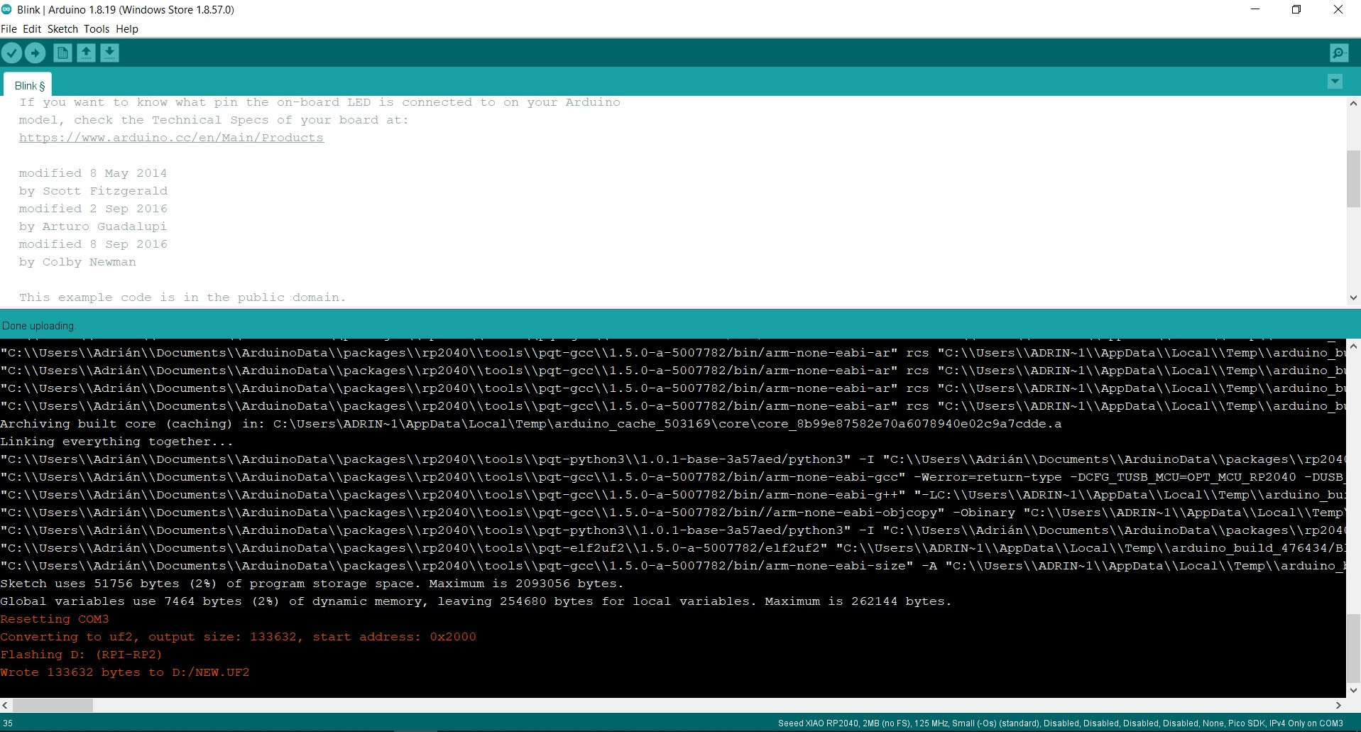
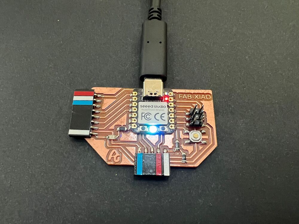
- 5. Now load the Blink program so that the LED on pin D6 (GPIO 0) blinks. When we upload it, all this information appears in the notifications section.
In this short video you can see the operation of a Blink on pin GPIO 0 (0 in Arduino) where the LED is integrated. 😍
Programming. Seeed Studio XIAO ESP32-C3 with Arduino
- 1. We open the Arduino program.
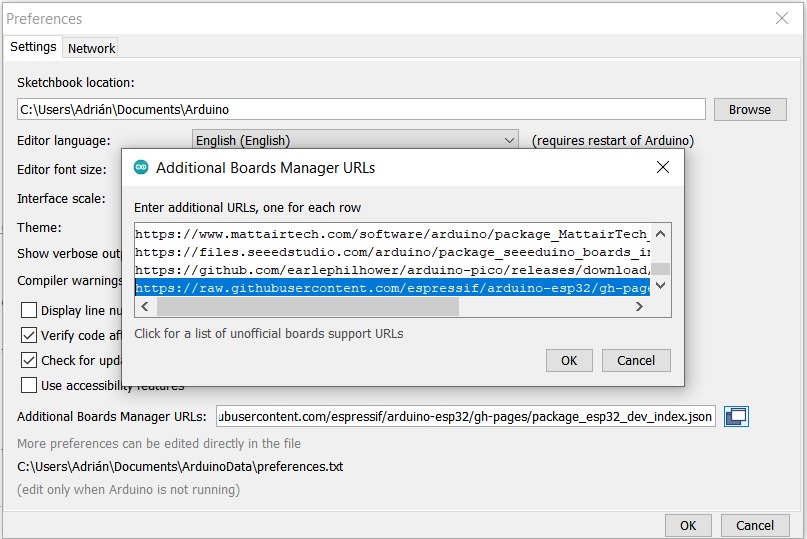
- 2. In Preferences, we will add the URL of the additional boards that you can find here. We need the Arduino ESP32 by Espressif
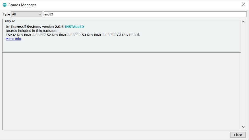
- 3. The next step is to download ESP32 in the boards manager.
- 4. We configure the Arduino IDE for the Seeed Studio XIAO ESP32-C3. The Seeed Studio XIAO ESP32-C3 will appear in the COM port, in my case in COM 3.
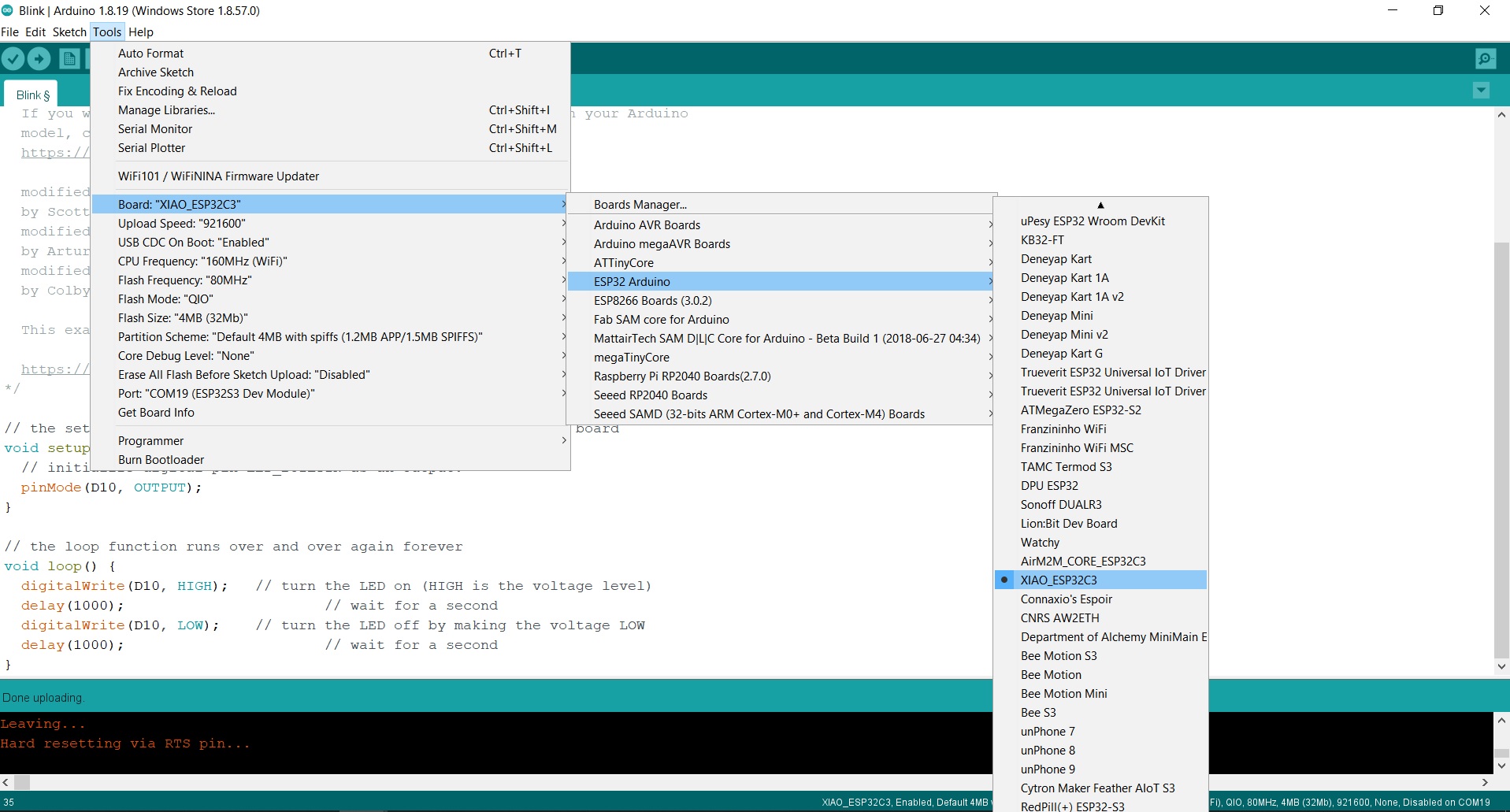
- 5. Now load the Blink program so that the LED on pin D6 blinks. When we upload it, all this information appears in the notifications section.
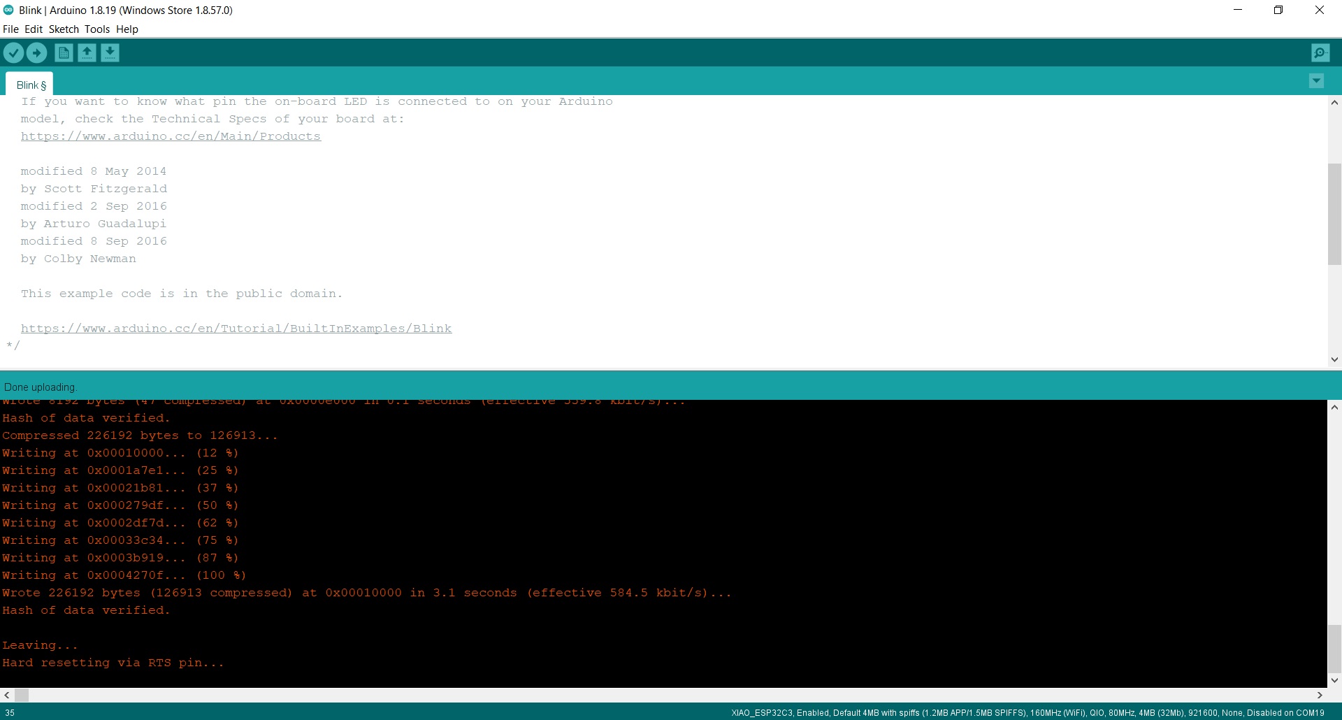
In this short video you can see the operation of a Blink on pin D6 where the LED is integrated. 😍
Inputs
Button
The button is the simplest element of the inputs. It is an open or closed contact that when we press it changes its state to closed or open.
In this case for the XIAO RP2040, the button is integrated on the board, on the GPIO 1 pin (Arduino pin 1) and the LED on the GPIO 0 pin (Arduino pin 0). In the XIAO ESP32-C3, the button is on the pin D7 and the LED on the pin D6.
Here you will find the programming to use the button. Here you can find the Arduino file to download.
//Fab Academy 2023 - Fab Lab León
//Button + LED
//Fab-Xiao
//
//Original code:Neil Gershenfeld 12/8/19
// This work may be reproduced, modified, distributed,
// performed, and displayed for any purpose, but must
// acknowledge this project. Copyright is retained and
// must be preserved. The work is provided as is; no
// warranty is provided, and users accept all liability.
//


const int ledPin1 = 0;//first light  RP2040 pin 0 or ESP32-C3 pin D6
const int buttonPin = 1;// button pin  RP2040 pin 1 or ESP32-C3 pin D7
int buttonState = 0;//initial state of the button
int i = 0; //variable intensity led

void setup() { //declaration of inputs and outputs
  pinMode(ledPin1, OUTPUT);
  pinMode(buttonPin, INPUT);
}
void loop() {
  buttonState = digitalRead(buttonPin);// we read the state of the button
  if (buttonState == HIGH) { //if we press the button
  digitalWrite(ledPin1, HIGH);
  delay(500);
  digitalWrite(ledPin1, LOW);
  delay(500);
  digitalWrite(ledPin1, HIGH);
  delay(500);
  digitalWrite(ledPin1, LOW);
  delay(500);
  digitalWrite(ledPin1, HIGH);
  delay(2000);
  digitalWrite(ledPin1, LOW);
  delay(1000);

}
  else {  //if we don't press the button
  digitalWrite(ledPin1, LOW);
  }
}
Touch
In this case, the touchpad is a button made of copper, and we're going to measure its resistance. Thanks to Quentin, who, for example, has made the QPAD.In this case, being a component without a module, I create my own. I design and manufacture a small board where I solder the flat connectors where there is no room for mistakes when connecting it. I use the analog input of the Seeed XIAO RP2040 GPIO 26 and GPIO 27 (Arduino pin 26 and 27).

Here you can find the design in Eagle and the PNG's to create the board.
Here you will find the programming to use the touch. Here you can find the Arduino file to download.
//Fab Academy 2026 - Fab Lab León
//Touch + LED
//Fab-Xiao
//

#define LED 0
#define N_TOUCH 2
#define THRESHOLD 2

int touch_pins[N_TOUCH] = {27, 26};
int touch_values[N_TOUCH] = {0};
int touch_mapped[N_TOUCH] = {0};

bool pin_touched_now[N_TOUCH] = {false};

void update_touch() {
  int t;
  int t_max = 200;
  int p;

  for (int i = 0; i < N_TOUCH; i++) {
    p = touch_pins[i];

    pinMode(p, OUTPUT);
    digitalWriteFast(p, LOW);
    delayMicroseconds(25);

    pinMode(p, INPUT_PULLUP);

    t = 0;
    while (!digitalReadFast(p) && t < t_max) {
      t++;
    }

    touch_values[i] = t;

    // Mapear a 0–255
    touch_mapped[i] = map(touch_values[i], 0, t_max, 0, 255);

    pin_touched_now[i] = touch_values[i] > THRESHOLD;
  }
}

void setup() {
  Serial.begin(115200);

  pinMode(LED, OUTPUT);
  digitalWrite(LED, HIGH); // LED apagado
}

void loop() {
  update_touch();

  // Control LED con pin 26 (índice 1)
  if (pin_touched_now[1]) {
    digitalWrite(LED, HIGH);  // encendido
  } else {
    digitalWrite(LED, LOW); // apagado
  }

  // Mostrar valores en Serial
  Serial.print("Touch 27: ");
  Serial.print(touch_mapped[0]);
  Serial.print(" | Touch 26: ");
  Serial.println(touch_mapped[1]);

  delay(50);
}
Phototransistor. Visible.
The Phototransistor sensor is a three-layer semiconductor device which has a light-sensitive base region. The base senses the light and converts it into the current which flows between the collector and the emitter region.
In this case, being a component without a module, I create my own. I design and manufacture a small board where I solder the Phototransistor sensor, a 10K resistor and with the flat connectors where there is no room for mistakes when connecting it. I use the analog input of the Seeed XIAO RP2040 GPIO 26 (Arduino pin 26).
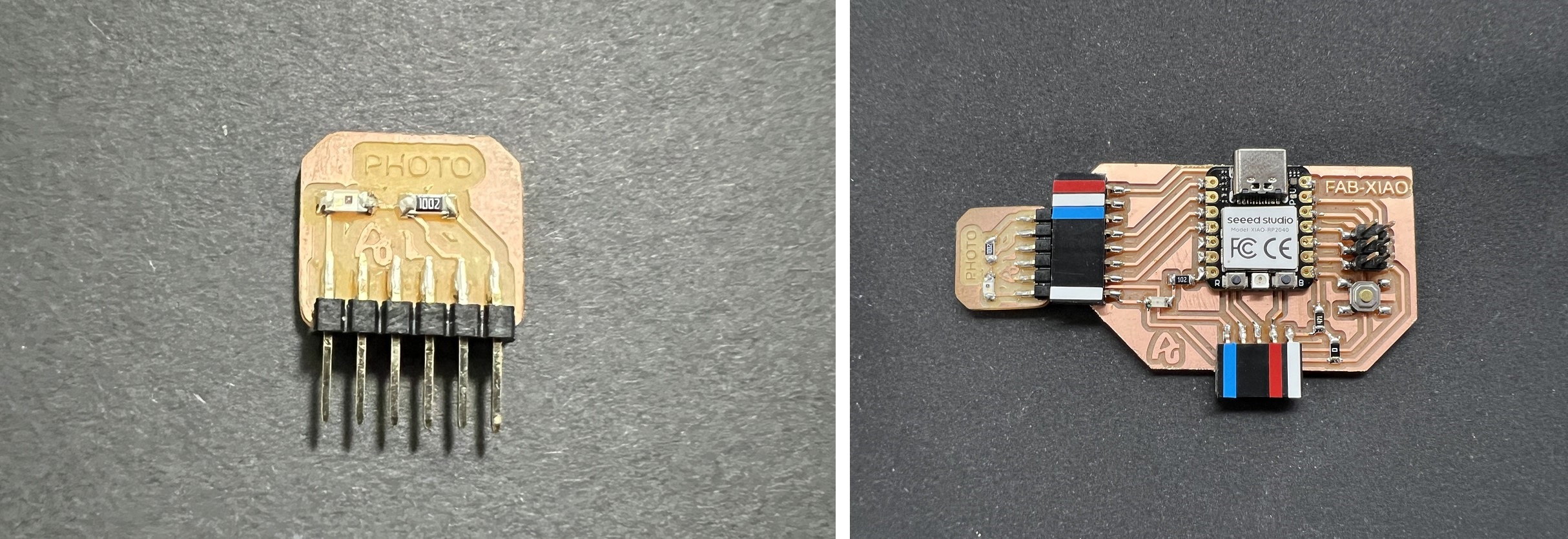
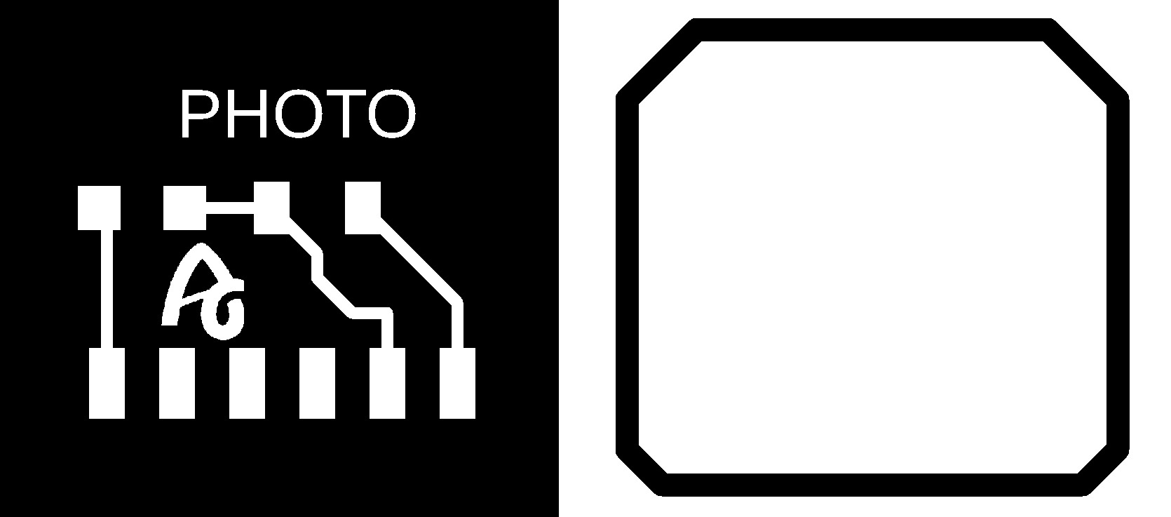
Here you can find the design in Eagle and the PNG's to create the board.
- Phototransistor Schematic + Board
Here you will find the programming to use an analog sensor such as the Phototransistor sensor. Here you can find the Arduino and Processing files to download.
- Arduino Hello Phototransistor sensor
- Processing Hello Phototransistor sensor
//Fab Academy 2023 - Fab Lab León
//Phototransistor
//Fab-Xiao

int sensorPin = A0;    // analog input pin RP2040 pin 26 or ESP32-C3 pin A0
int sensorValue = 0;  // variable to store the value coming from the sensor

void setup() {
  Serial.begin(115200); // initialize serial communications
}

void loop() {
  sensorValue = analogRead(sensorPin); // read the value from the sensor
  sensorValue = map(sensorValue, 0, 1024, 1024, 0);
  Serial.println(sensorValue); // print value to Serial Monitor
  //mySerial.println("x"); // print value "x" to Serial Monitor
  delay(50); // short delay so we can actually see the numbers
}
Phototransistor. IR.
The Phototransistor IR sensor is a three-layer semiconductor device which has a light-sensitive base region. The base senses the IR and converts it into the current which flows between the collector and the emitter region.
In this case, being a component without a module, I create my own. I design and manufacture a small board where I solder the Phototransistor IR sensor, a 10K resistor, a IR LED, a 1K resistor and with the flat connectors where there is no room for mistakes when connecting it. I use the analog input of the Seeed XIAO RP2040 GPIO 26 (Arduino pin 26).
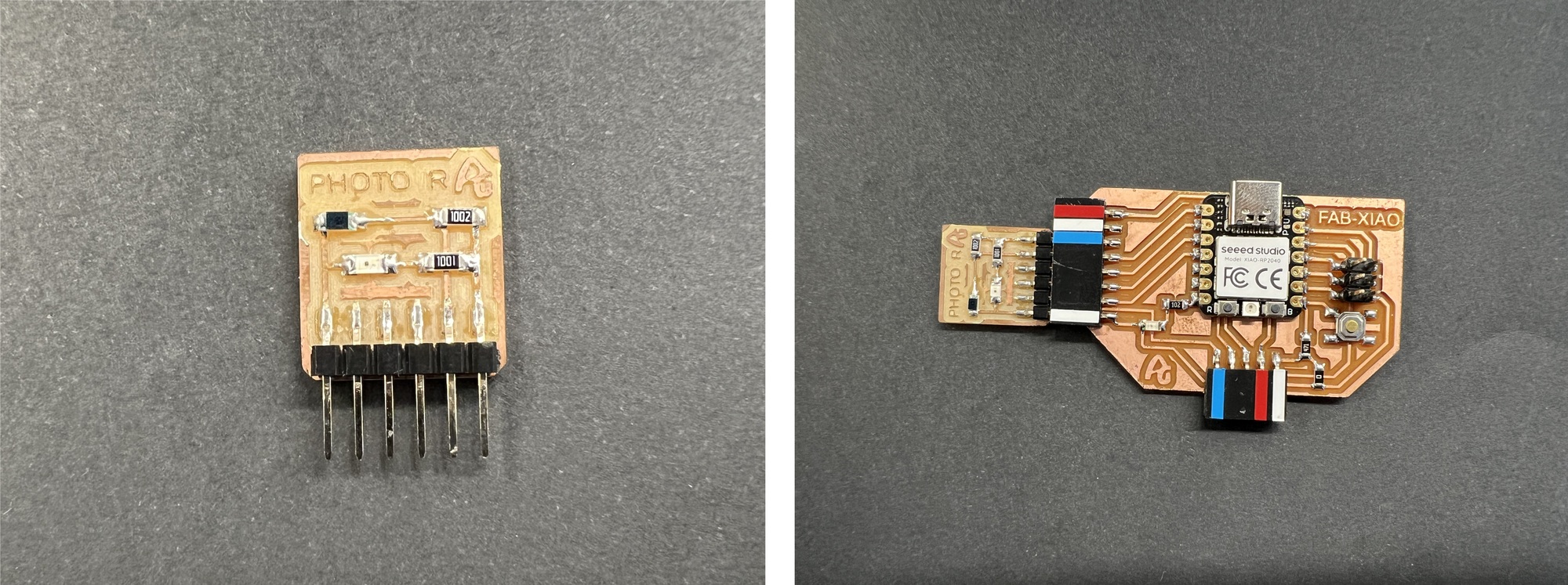
Here you can find the design in Eagle and the PNG's to create the board.
- Phototransistor IR Schematic + Board
- Phototransistor IR traces and interior

Here you will find the programming to use an analog sensor such as the Phototransistor sensor. Here you can find the Arduino and Processing files to download. Below you can see a video of how it works.
- Arduino Hello Phototransistor IR sensor
- Processing Hello Phototransistor IR sensor
/******************************************************************************
QRD1114_Proximity_Example.ino
Example sketch for SparkFun's QRD1114 Reflectance Proximity Sensor
  (https://www.sparkfun.com/products/246)
Jim Lindblom @ SparkFun Electronics
May 2, 2016

Modified by Adrián Torres Omaña
Fab Lab LeÓN
Phototransistor IR
Fab-Xiao


******************************************************************************/
const int Sensor = 26; // analog input pin RP2040 pin 26 or ESP32-C3 pin A0

void setup()
{
  Serial.begin(115200);
  pinMode(Sensor, INPUT);
}

void loop()
{
  // Read in the ADC and convert it to a voltage:
  int proximityADC = analogRead(Sensor);
  float proximityV = (float)proximityADC * 1000.0 / 1023.0;
  Serial.println(proximityV);
  delay(100);
}
Step Response.
The step-response is a sensor that is made with two sheets of copper, separated from each other by a porous insulating material. It can be used to calculate the value of force, weight, resistance ... I have followed Robert Hart's tutorial as well as Neil's examples.
A series of pulses is sent through the TX electrode, which, depending on the material between the two electrodes, allows more or less that series of pulses to pass. In the following graph you can see how it works. The other electrode will be connected between two resistors, one for pull-up and the other for pull-down and to an analog input.
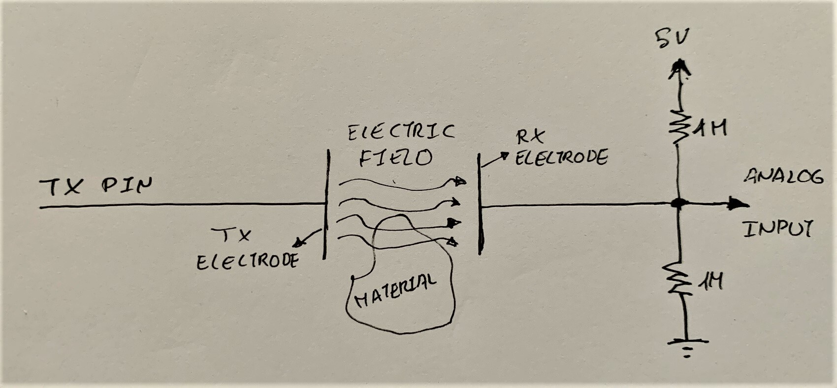
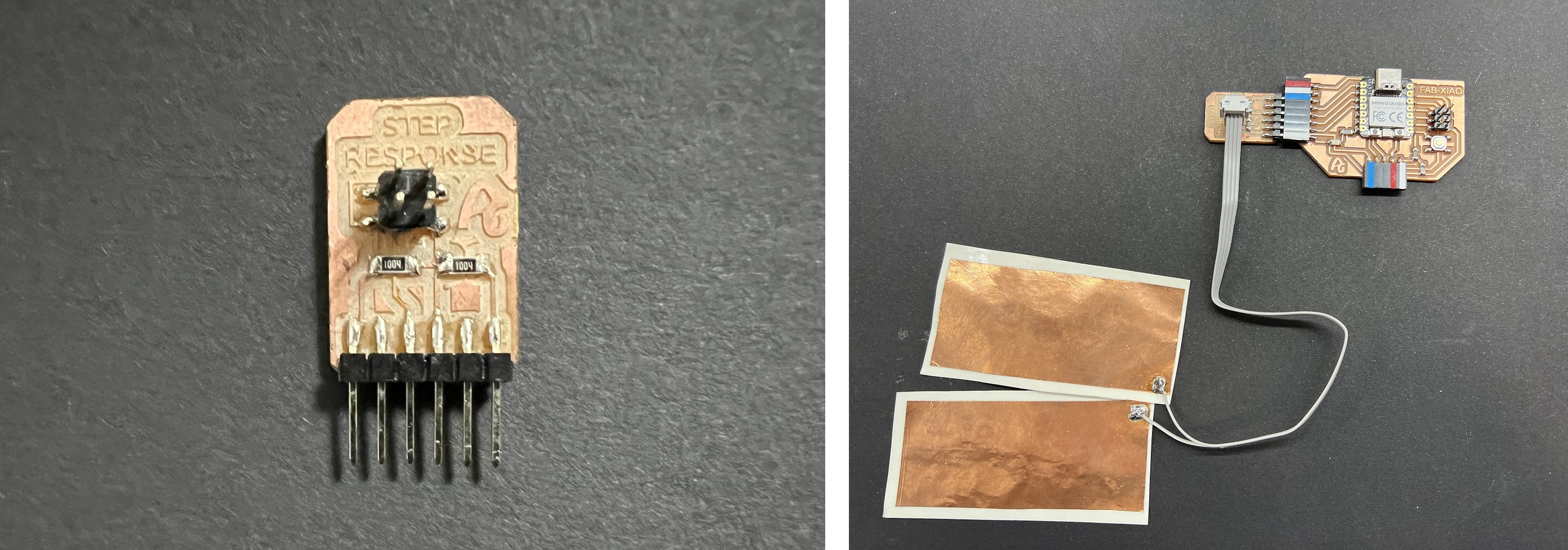
In this case, being a component without a module, I create my own. I design and manufacture a small board where I solder two 1M resistors and with flat connectors where there is no room for errors when connecting it. I use the analog input from the Seeed XIAO RP2040 GPIO 27 (Arduino pin 27) for the RX and a digital output from the Seeed XIAO RP2040 GPIO 28 (Arduino pin 28). Then with a connector there are two cables that connect the two electrodes (3M™ Copper Foil Tape).
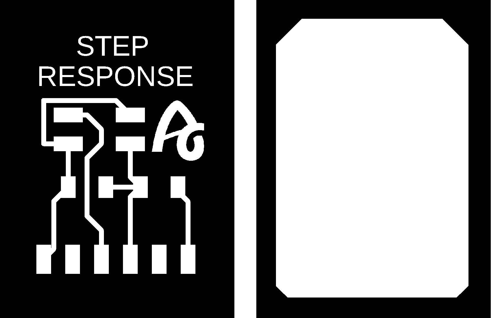
Here you can find the design in Eagle and the PNG's to create the board.
- Step Response Schematic + Board
Here you will find the programming to use a Step Response sensor. Here you can find the Arduino and Processing files to download. Below you can see a video of how it works.
- Processing Step Response TX/RX
//tx_rx03  Robert Hart Mar 2019.
//https://roberthart56.github.io/SCFAB/SC_lab/Sensors/tx_rx_sensors/index.html

//Modified by Adrián Torres Omaña
//Fab Academy 2023 - Fab Lab León
//Step Response TX, RX
//Fab-Xiao

//  Program to use transmit-receive across space between two conductors.
//  One conductor attached to digital pin, another to analog pin.
//
//  This program has a function "tx_rx() which returns the value in a long integer.
//
//  Optionally, two resistors (1 MOhm or greater) can be placed between 5V and GND, with
//  the signal connected between them so that the steady-state voltage is 2.5 Volts.
//
//  Signal varies with electric field coupling between conductors, and can
//  be used to measure many things related to position, overlap, and intervening material
//  between the two conductors.
//


long result;   //variable for the result of the tx_rx measurement.
int analog_pin = 27; //  GPIO 27 of the XIA0 RP2040 or ESP32-C3 pin A1
int tx_pin = 28;  //     GPIO 28 of the XIAO RP2040 or ESP32-C3 pin D2
void setup() {
pinMode(tx_pin,OUTPUT);      //Pin 2 provides the voltage step
Serial.begin(115200);
}


long tx_rx(){         //Function to execute rx_tx algorithm and return a value
                      //that depends on coupling of two electrodes.
                      //Value returned is a long integer.
  int read_high;
  int read_low;
  int diff;
  long int sum;
  int N_samples = 100;    //Number of samples to take.  Larger number slows it down, but reduces scatter.

  sum = 0;

  for (int i = 0; i < N_samples; i++){
   digitalWrite(tx_pin,HIGH);              //Step the voltage high on conductor 1.
   read_high = analogRead(analog_pin);        //Measure response of conductor 2.
   delayMicroseconds(100);            //Delay to reach steady state.
   digitalWrite(tx_pin,LOW);               //Step the voltage to zero on conductor 1.
   read_low = analogRead(analog_pin);         //Measure response of conductor 2.
   diff = read_high - read_low;       //desired answer is the difference between high and low.
 sum += diff;                       //Sums up N_samples of these measurements.
 }
  return sum;
}                         //End of tx_rx function.


void loop() {

result = tx_rx();
result = map(result, 17000, 23000, 0, 1024);  //I recommend mapping the values of the two copper plates, it will depend on their size
Serial.println(result);
delay(100);
}
This first video you can see how the two electrodes work with several sheets as intermediate material.
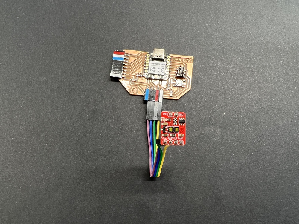
Time of flight VL53L1X
I use a module that integrates the VL53L1X sensor. The module is sold by Polulu, although in my case I bought it from Amazon. In this case of the pinout that the sensor brings, I will only use the VCC, GND, SDA and SCL pins.
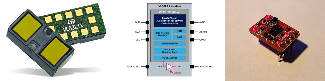
In this case we only need four cables; one for VCC, one for GND, another cable for the SDA and SCL, the I2C connection.
Here you will find the programming to use the Time of Flight VL53L1X sensor. Here you can find the Arduino and Processing files to download. Below you can see a video of how it works. Recommendation: Download the program from the link, in the text the symbols <> of the libraries are missing.
- Arduino Time of Flight VL53L1X sensor
- Processing Time of Flight VL53L1X sensor
//Fab Academy 2023 - Fab Lab León
//Time of Flight VL53L1X
//Fab-Xiao
/*
This example shows how to take simple range measurements with the VL53L1X. The
range readings are in units of mm.
*/
#include
#include
VL53L1X sensor;
void setup()
{
Serial.begin(115200);
Wire.begin();
Wire.setClock(400000); // use 400 kHz I2C
sensor.setTimeout(500);
if (!sensor.init())
{
Serial.println("Failed to detect and initialize sensor!");
while (1);
}
// Use long distance mode and allow up to 50000 us (50 ms) for a measurement.
// You can change these settings to adjust the performance of the sensor, but
// the minimum timing budget is 20 ms for short distance mode and 33 ms for
// medium and long distance modes. See the VL53L1X datasheet for more
// information on range and timing limits.
sensor.setDistanceMode(VL53L1X::Long);
sensor.setMeasurementTimingBudget(50000);
// Start continuous readings at a rate of one measurement every 50 ms (the
// inter-measurement period). This period should be at least as long as the
// timing budget.
sensor.startContinuous(50);
}
void loop()
{
Serial.print(sensor.read());
if (sensor.timeoutOccurred()) { Serial.print(" TIMEOUT"); }
Serial.println();
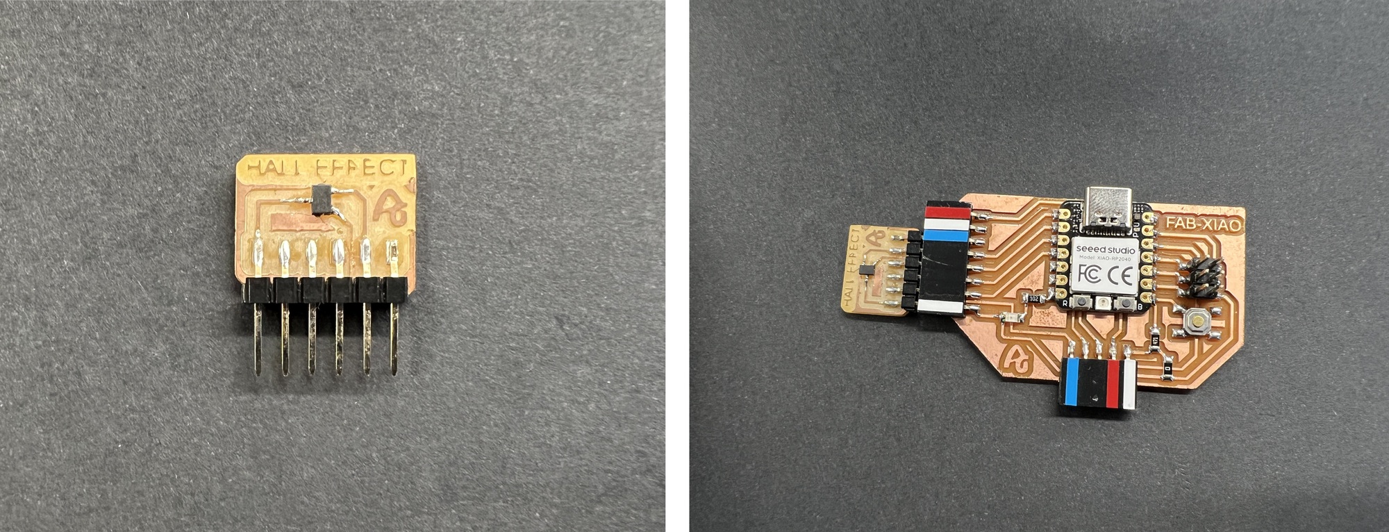
} Hall effect
The Hall effect sensor or simply Hall sensor or Hall probe uses the Hall effect to measure magnetic fields or currents or to determine the position in which it is.
In this case, being a component without a module, I create my own. I design and manufacture a small board where I solder the hall effect sensor and with the flat connectors where there is no room for mistakes when connecting it. I use the analog input of the Seeed XIAO RP2040 GPIO 26 (Arduino pin 26).
Here you can find the design in Eagle and the PNG's to create the board.
- Hall effect Schematic + Board
- Hall effect traces and interior
Here you will find the programming to use an analog sensor such as the Hall effect sensor. Here you can find the Arduino and Processing files to download. Below you can see a video of how it works.
- Arduino Hello Hall effect sensor
- Processing Hello Hall effect sensor
//Fab Academy 2023 - Fab Lab León
//Hall effect
//Fab-Xiao
int sensorPin = A0; // analog input pin RP2040 pin 26 or ESP32-C3 pin A0
int sensorValue = 0; // variable to store the value coming from the sensor
void setup() {
Serial.begin(115200); // initialize serial communications
}
void loop() {
sensorValue = analogRead(sensorPin); // read the value from the sensor
sensorValue = map(sensorValue, 200, 800, 1024, 0);
Serial.println(sensorValue); // print value to Serial Monitor
//mySerial.println("x"); // print value "x" to Serial Monitor
delay(50); // short delay so we can actually see the numbers
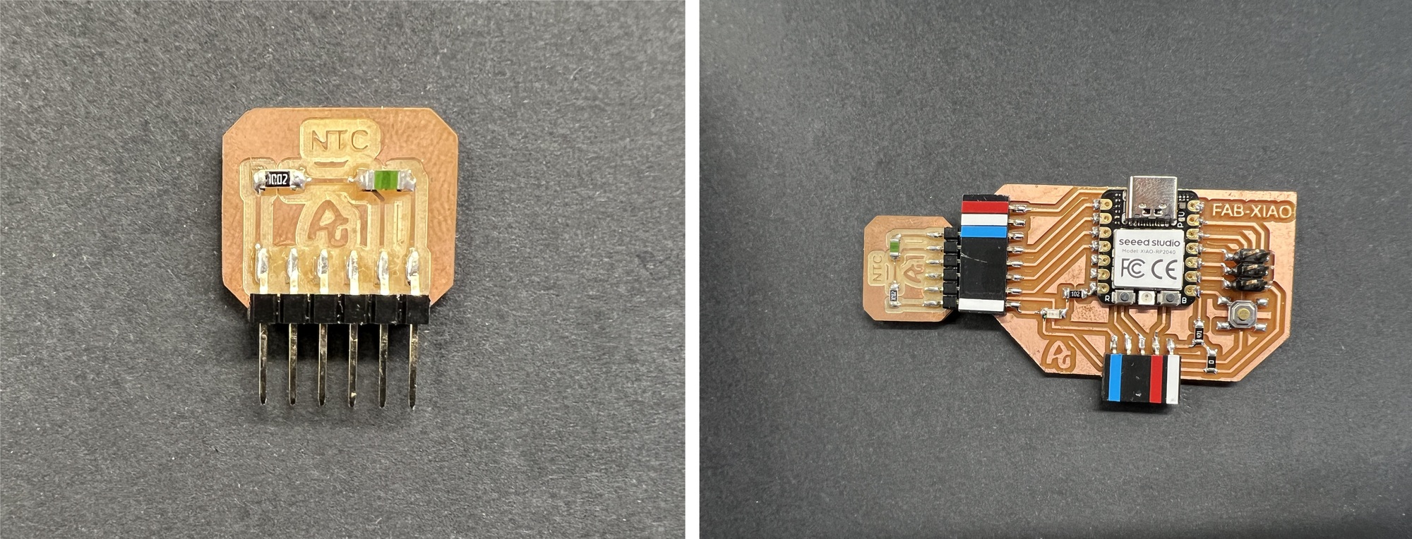
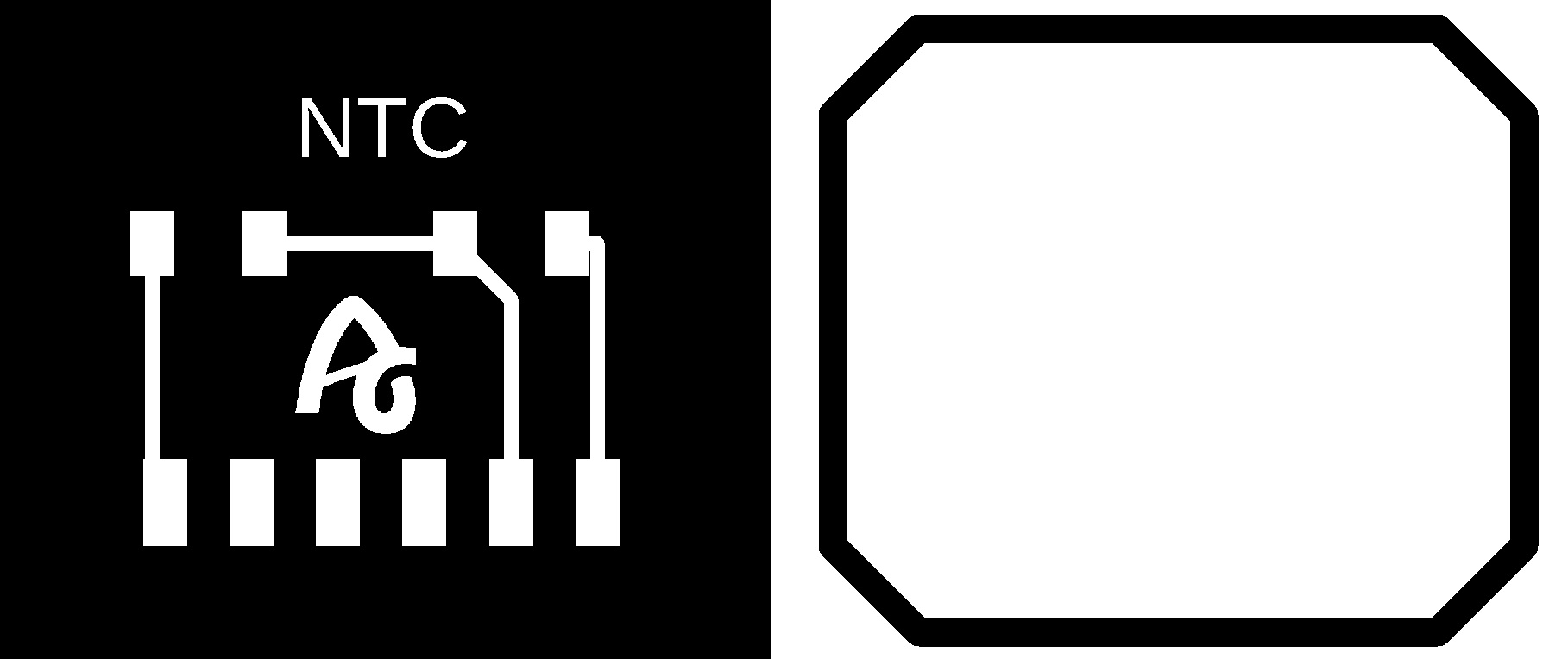
}Temperature. NTC.
The NTC sensor is a type of resistance whose value varies as a function of temperature in a more pronounced way than a common resistance. Its operation is based on the variation of the resistivity that a semiconductor presents with temperature.
In this case, being a component without a module, I create my own. I design and manufacture a small board where I solder the NTC sensor, a 10K resistor and with the flat connectors where there is no room for mistakes when connecting it. I use the analog input of the Seeed XIAO RP2040 GPIO 26 (Arduino pin 26).
Here you can find the design in Eagle and the PNG's to create the board.
Here you will find the programming to use an analog sensor such as the NTC sensor. Here you can find the Arduino and Processing files to download. Below you can see a video of how it works.
- Arduino Hello NTC Temperature sensor
- Processing Hello NTC Temperature sensor
//Fab Academy 2023 - Fab Lab León
//Fab-Xiao

int sensorPin = 26;   // analog input pin RP2040 pin 26 or ESP32-C3 pin A0
int sensorValue = 0;  // variable to store the value coming from the sensor

void setup() {
  Serial.begin(115200); // initialize serial communications
}

void loop() {
  sensorValue = analogRead(sensorPin); // read the value from the sensor
  sensorValue = map(sensorValue, 482, 890, 19, 180);
  Serial.println(sensorValue); // print value to Serial Monitor
  //mySerial.println("x"); // print value "x" to Serial Monitor
  delay(500); // short delay so we can actually see the numbers
}
Doppler radar
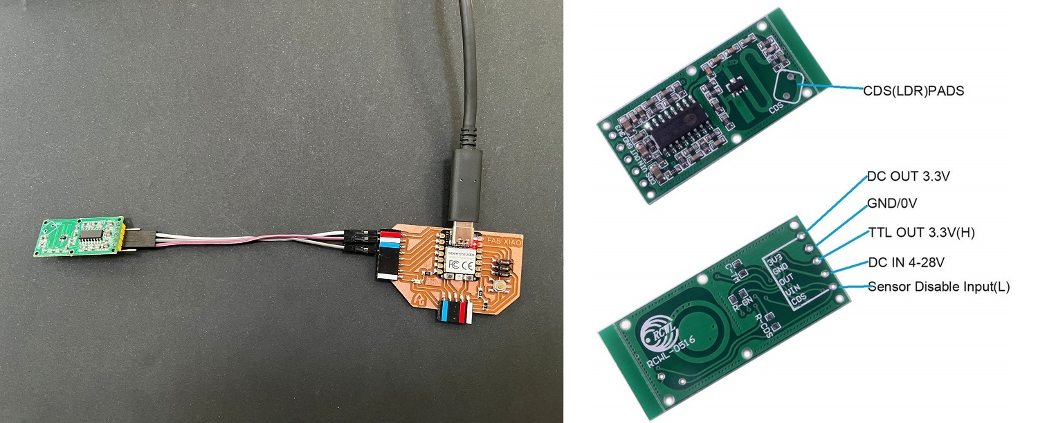
The RCWL-0516 is a Dopler Microwave Radar Sensor.It is an alternative to traditional PIR infrared motion detectors. Faced with these, it has certain differences, which will be an advantage or disadvantage depending on the needs of our project.
First of all, PIR sensors require the moving object to have a temperature difference from the environment. For this reason, they are able to detect people, but not moving objects. In contrast, the RCWL-0516 detects any object that is moving, regardless of its temperature. On the other hand, PIR sensors have sensitivity problems when the ambient temperature is high. The RCWL-0516, on the other hand, does not have this problem and works correctly between -20ºC to 80ºC. In terms of detection range, the RCWL-0516 has a greater range than PIR sensors, being able to easily reach 5-7 meters of range.
Finally, the RCWL-0516 is omnidirectional, that is, it detects movement in 360º. This is a difference from PIR sensors, which have a certain "angle of view". There are even versions of PIR with a narrow beam, for example to control windows or doors.
In this case we only need three cables; one for VCC, another for GND and another for the sensor output that in our case we will connect it to Seeed XIAO RP2040 GPIO 26 (Arduino pin 26).
Here you will find the programming to use a digital sensor such as the PIR. Here you can find the Arduino and Processing files to download. Below you can see a video of how it works.
//Fab Academy 2023 - Fab Lab León
//PIR sensor or Doppler radar
//Fab-Xiao


const int RadarPin = 26; // digital input pin RP2040 pin 26 or ESP32-C3 pin D0
int value = 6; // variable to store the value coming from the sensor
void setup()
{
  Serial.begin(115200); // initialize serial communications
  pinMode(RadarPin, INPUT); //digital input pin
}

void loop()
{
  int value= digitalRead(RadarPin); // read the value from the sensor (0 or 1)
  Serial.println(value);  // print value to Serial Monitor
}
Outputs
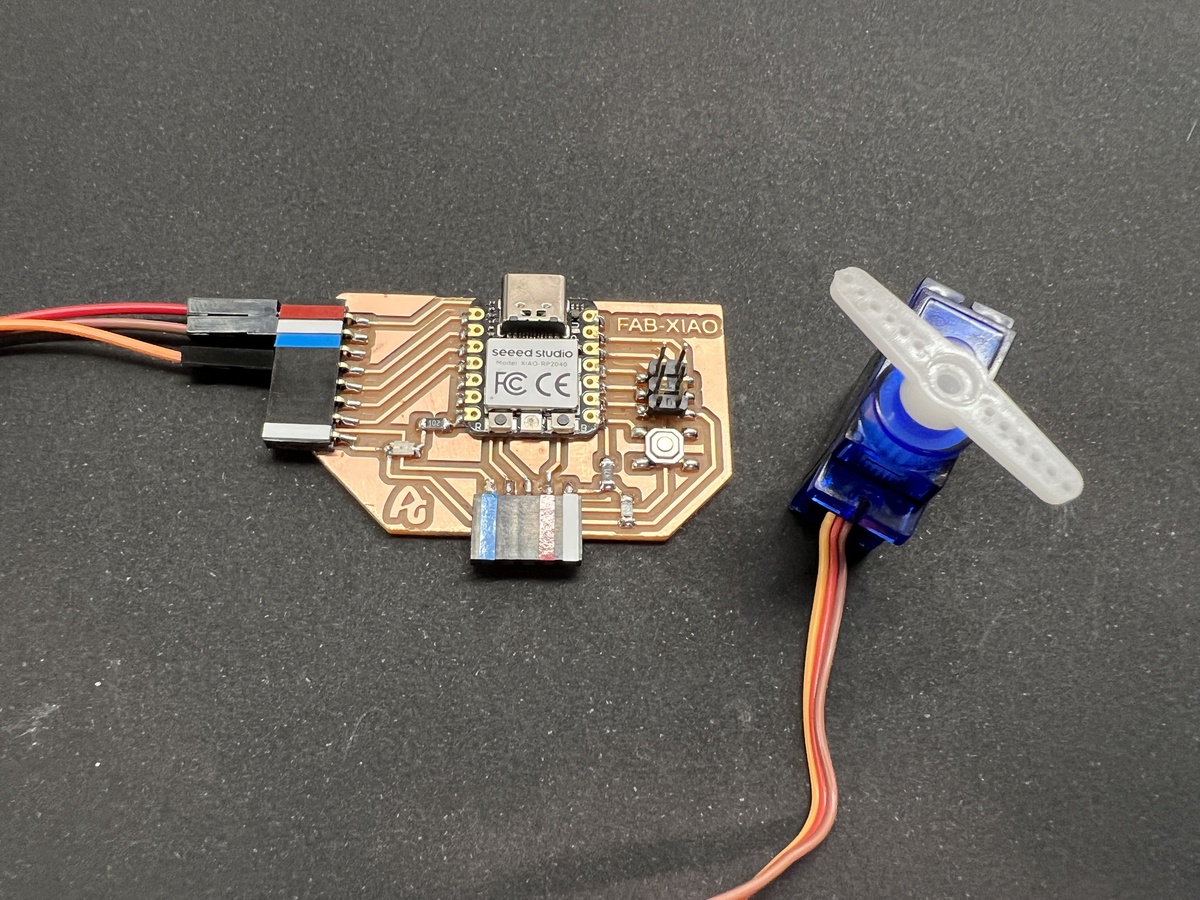
Servo motor
A very common output is a servo. A servomotor is a device similar to a direct current motor that has the ability to be located in any position within its operating range, and remain stable in that position. In this case I use a 0 to 180 degree servo.
In this case we only need three cables; one for VCC, another for GND and another for the signal output that in our case we will connect it to pin GPIO 26 (26 in Arduino). IMPORTANT: We must supply the servo with 5V.
Here you will find the programming to use a servo motor. Here you can find the Arduino file to download.
/* Sweep
by BARRAGAN
This example code is in the public domain.
modified 28 May 2015
by Michael C. Miller
modified 8 Nov 2013
by Scott Fitzgerald
http://arduino.cc/en/Tutorial/Sweep
*/
//Modified by Adrián Torres Omaña
//Fab Academy 2023 - Fab Lab León
//Servo
//Fab-Xiao
#include
Servo myservo; // create servo object to control a servo
// twelve servo objects can be created on most boards
void setup() {
myservo.attach(26); // attaches the servo on GIO26 to the servo object
}
void loop() {
int pos;
for (pos = 0; pos <= 180; pos += 1) { // goes from 0 degrees to 180 degrees
// in steps of 1 degree
myservo.write(pos); // tell servo to go to position in variable 'pos'
delay(15); // waits 15ms for the servo to reach the position
}
for (pos = 180; pos >= 0; pos -= 1) { // goes from 180 degrees to 0 degrees
myservo.write(pos); // tell servo to go to position in variable 'pos'
delay(15); // waits 15ms for the servo to reach the position
}
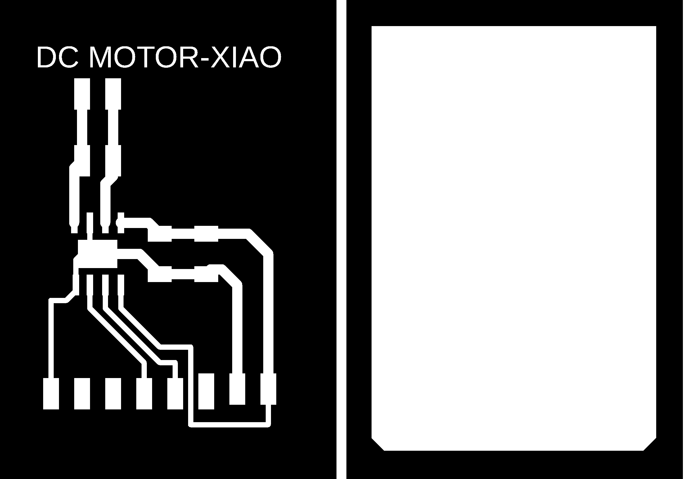
} DC motor
To control a DC motor we will use an H bridge, such as the Toshiba TB67H451FNG. With this driver we can control all types of motors through PWM signals.
In this case, being a component without a module, I create my own. I design and manufacture a small board where I solder the Toshiba TB67H451FNG driver, a 1uF capacitor, a 10uF capacitor and with the flat connectors where there is no room for mistakes when connecting it. It includes two traces to feed with the 5V and ground. I use two digital output of the XIAO RP2040 GPIO 26 (Arduino pin 26) and GPIO 27 (Arduino pin 27).

Here you can find the design in Eagle and the PNG's to create the board.
Here you will find the programming to use a servo motor. Here you can find the Arduino file to download.
//Fab Academy 2023 - Fab Lab León
//Motor
//Adrianino
//Fab-Xiao RP2040
const int switch1Pin = 1;     // switch 1
const int motor1Pin = 26;      // H-bridge pin 0 (in2)
const int motor2Pin = 27;      // H-bridge pin 1 (in1)

void setup() {
    // set the switch pins as input pins and activate their internal pull up resistors
    // so they are not in a floating state because their default state is now HIGH
    pinMode(switch1Pin, INPUT);


    // set H-bridge pins as outputs:
    pinMode(motor1Pin, OUTPUT);
    pinMode(motor2Pin, OUTPUT);
  }

void loop() {
    // if switch1 is pressed, (=LOW because the unpressed 'pulled up' state is HIGH)

  if (digitalRead(switch1Pin) == HIGH) {
      analogWrite(motor1Pin, 255); // set pin 1 of the H-bridge to 50% using PWM
      analogWrite(motor2Pin, 0);   // set pin 2 of the H-bridge to low state
    }
     // if neither of the switches are pressed, the motor will stand still
  else
      {
      digitalWrite(motor1Pin, 0);   // set pin 1 of the H-bridge low
      digitalWrite(motor2Pin, 255);   // set pin 2 of the H-bridge low
      }
  }
Speaker
To control a Speaker we will use an H bridge, such as the Toshiba TB67H451FNG. With this driver we can control all types of motors through PWM signals.
In this case, being a component without a module, I create my own. I design and manufacture a small board where I solder the Toshiba TB67H451FNG driver, a 1uF capacitor, a 10uF capacitor and with the flat connectors where there is no room for mistakes when connecting it. It includes two traces to feed with the 5V and ground. I use two digital output of the XIAO RP2040 GPIO 26 (Arduino pin 26) and GPIO 27 (Arduino pin 27).
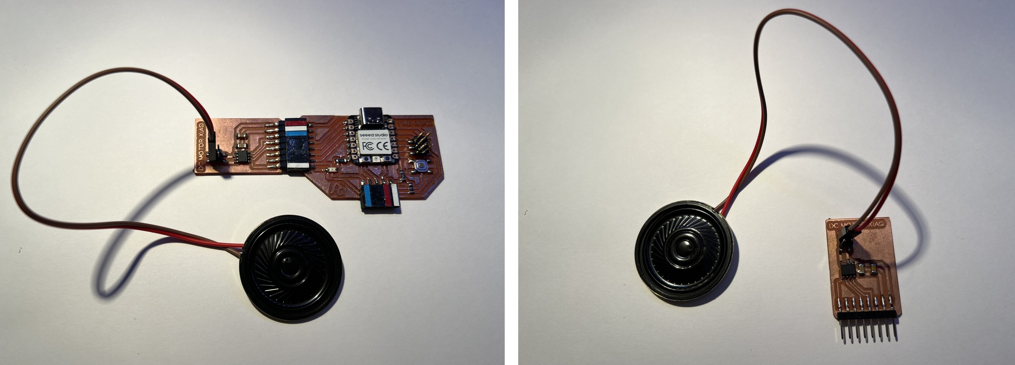
Here you can find the design in Eagle and the PNG's to create the board.
- Speaker Driver Schematic + Board
- Speaker Driver traces and interior
Here you will find the programming to use a speaker. May the force be with you Here you can find the Arduino file to download.
//Fab Academy 2024 - Fab Lab León
//Speaker
//Fab-Xiao RP2040

/*
  Star Wars theme
  Connect a piezo buzzer or speaker to pin 11 or select a new pin.
  More songs available at https://github.com/robsoncouto/arduino-songs

                                              Robson Couto, 2019
*/

#define NOTE_B0  31
#define NOTE_C1  33
#define NOTE_CS1 35
#define NOTE_D1  37
#define NOTE_DS1 39
#define NOTE_E1  41
#define NOTE_F1  44
#define NOTE_FS1 46
#define NOTE_G1  49
#define NOTE_GS1 52
#define NOTE_A1  55
#define NOTE_AS1 58
#define NOTE_B1  62
#define NOTE_C2  65
#define NOTE_CS2 69
#define NOTE_D2  73
#define NOTE_DS2 78
#define NOTE_E2  82
#define NOTE_F2  87
#define NOTE_FS2 93
#define NOTE_G2  98
#define NOTE_GS2 104
#define NOTE_A2  110
#define NOTE_AS2 117
#define NOTE_B2  123
#define NOTE_C3  131
#define NOTE_CS3 139
#define NOTE_D3  147
#define NOTE_DS3 156
#define NOTE_E3  165
#define NOTE_F3  175
#define NOTE_FS3 185
#define NOTE_G3  196
#define NOTE_GS3 208
#define NOTE_A3  220
#define NOTE_AS3 233
#define NOTE_B3  247
#define NOTE_C4  262
#define NOTE_CS4 277
#define NOTE_D4  294
#define NOTE_DS4 311
#define NOTE_E4  330
#define NOTE_F4  349
#define NOTE_FS4 370
#define NOTE_G4  392
#define NOTE_GS4 415
#define NOTE_A4  440
#define NOTE_AS4 466
#define NOTE_B4  494
#define NOTE_C5  523
#define NOTE_CS5 554
#define NOTE_D5  587
#define NOTE_DS5 622
#define NOTE_E5  659
#define NOTE_F5  698
#define NOTE_FS5 740
#define NOTE_G5  784
#define NOTE_GS5 831
#define NOTE_A5  880
#define NOTE_AS5 932
#define NOTE_B5  988
#define NOTE_C6  1047
#define NOTE_CS6 1109
#define NOTE_D6  1175
#define NOTE_DS6 1245
#define NOTE_E6  1319
#define NOTE_F6  1397
#define NOTE_FS6 1480
#define NOTE_G6  1568
#define NOTE_GS6 1661
#define NOTE_A6  1760
#define NOTE_AS6 1865
#define NOTE_B6  1976
#define NOTE_C7  2093
#define NOTE_CS7 2217
#define NOTE_D7  2349
#define NOTE_DS7 2489
#define NOTE_E7  2637
#define NOTE_F7  2794
#define NOTE_FS7 2960
#define NOTE_G7  3136
#define NOTE_GS7 3322
#define NOTE_A7  3520
#define NOTE_AS7 3729
#define NOTE_B7  3951
#define NOTE_C8  4186
#define NOTE_CS8 4435
#define NOTE_D8  4699
#define NOTE_DS8 4978
#define REST      0


// change this to make the song slower or faster
int tempo = 108;

// change this to whichever pin you want to use
int buzzer = 26;

// notes of the moledy followed by the duration.
// a 4 means a quarter note, 8 an eighteenth , 16 sixteenth, so on
// !!negative numbers are used to represent dotted notes,
// so -4 means a dotted quarter note, that is, a quarter plus an eighteenth!!
int melody[] = {

  // Dart Vader theme (Imperial March) - Star wars
  // Score available at https://musescore.com/user/202909/scores/1141521
  // The tenor saxophone part was used

  NOTE_AS4,8, NOTE_AS4,8, NOTE_AS4,8,//1
  NOTE_F5,2, NOTE_C6,2,
  NOTE_AS5,8, NOTE_A5,8, NOTE_G5,8, NOTE_F6,2, NOTE_C6,4,
  NOTE_AS5,8, NOTE_A5,8, NOTE_G5,8, NOTE_F6,2, NOTE_C6,4,
  NOTE_AS5,8, NOTE_A5,8, NOTE_AS5,8, NOTE_G5,2, NOTE_C5,8, NOTE_C5,8, NOTE_C5,8,
  NOTE_F5,2, NOTE_C6,2,
  NOTE_AS5,8, NOTE_A5,8, NOTE_G5,8, NOTE_F6,2, NOTE_C6,4,

  NOTE_AS5,8, NOTE_A5,8, NOTE_G5,8, NOTE_F6,2, NOTE_C6,4, //8
  NOTE_AS5,8, NOTE_A5,8, NOTE_AS5,8, NOTE_G5,2, NOTE_C5,-8, NOTE_C5,16,
  NOTE_D5,-4, NOTE_D5,8, NOTE_AS5,8, NOTE_A5,8, NOTE_G5,8, NOTE_F5,8,
  NOTE_F5,8, NOTE_G5,8, NOTE_A5,8, NOTE_G5,4, NOTE_D5,8, NOTE_E5,4,NOTE_C5,-8, NOTE_C5,16,
  NOTE_D5,-4, NOTE_D5,8, NOTE_AS5,8, NOTE_A5,8, NOTE_G5,8, NOTE_F5,8,

  NOTE_C6,-8, NOTE_G5,16, NOTE_G5,2, REST,8, NOTE_C5,8,//13
  NOTE_D5,-4, NOTE_D5,8, NOTE_AS5,8, NOTE_A5,8, NOTE_G5,8, NOTE_F5,8,
  NOTE_F5,8, NOTE_G5,8, NOTE_A5,8, NOTE_G5,4, NOTE_D5,8, NOTE_E5,4,NOTE_C6,-8, NOTE_C6,16,
  NOTE_F6,4, NOTE_DS6,8, NOTE_CS6,4, NOTE_C6,8, NOTE_AS5,4, NOTE_GS5,8, NOTE_G5,4, NOTE_F5,8,
  NOTE_C6,1

};

// sizeof gives the number of bytes, each int value is composed of two bytes (16 bits)
// there are two values per note (pitch and duration), so for each note there are four bytes
int notes = sizeof(melody) / sizeof(melody[0]) / 2;

// this calculates the duration of a whole note in ms
int wholenote = (60000 * 4) / tempo;

int divider = 0, noteDuration = 0;

void setup() {
  // iterate over the notes of the melody.
  // Remember, the array is twice the number of notes (notes + durations)
  for (int thisNote = 0; thisNote < notes * 2; thisNote = thisNote + 2) {

    // calculates the duration of each note
    divider = melody[thisNote + 1];
    if (divider > 0) {
      // regular note, just proceed
      noteDuration = (wholenote) / divider;
    } else if (divider < 0) {
      // dotted notes are represented with negative durations!!
      noteDuration = (wholenote) / abs(divider);
      noteDuration *= 1.5; // increases the duration in half for dotted notes
    }

    // we only play the note for 90% of the duration, leaving 10% as a pause
    tone(buzzer, melody[thisNote], noteDuration*0.9);

    // Wait for the specief duration before playing the next note.
    delay(noteDuration);

    // stop the waveform generation before the next note.
    noTone(buzzer);
  }
}

void loop() {
  // no need to repeat the melody.
}
OLED
For this example I am going to use an OLED with an I2C communication module. In my case, I bought it through Amazon from AZDelivery, here is the link. This company has a multitude of very interesting tutorials, including that of the OLED module with I2C.
In this case we only need four cables; one for VCC, one for GND, another cable for the SDA and SCL, the I2C connection.
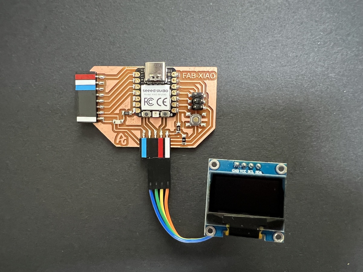
You will need to install the Adafruit SSD1306 and u8g2 libraries. If you need more information you can follow the following tutorial. Below you can see a video of how it works. Recommendation: Download the program from the link, in the text the symbols <> of the libraries are missing.
//Original code davekw7x https://forum.seeedstudio.com/t/arduino-boards-manager/263531/6
//Modified by Adrian Torres
//Fab Academy 2023 - Fab Lab León
//OLED
//Fab-Xiao

#include  // In U8g2 library

// Seeed Expansion board uses SSD1306
U8G2_SSD1306_128X64_NONAME_F_HW_I2C u8g2(U8G2_R0, /* reset= */ U8X8_PIN_NONE);

// My breadboard has an SH1106
//U8G2_SH1106_128X64_NONAME_F_HW_I2C u8g2(U8G2_R0, /* reset=*/ U8X8_PIN_NONE);

void setup(void) {
  // Change #if 0 to #if 1 to print some stuff
  // If you do, it will wait until you open the Serial Monitor
#if 0
  Serial.begin(115200);
  while (!Serial) {}
  delay(100);
  Serial.println("\nOLED u8g2lib test compiled on " __DATE__ " at " __TIME__);
#endif
  u8g2.begin();
}

char printBuffer[30];
uint8_t passno;
void loop(void) {
  snprintf(printBuffer, sizeof(printBuffer), "%3d", ++passno);
  u8g2.clearBuffer();                   // clear the internal memory
  u8g2.setFont(u8g2_font_ncenB08_tr);   // choose a suitable font
  u8g2.drawStr(0, 10, "Hello World!");
  u8g2.drawStr(0, 25, "Fab Academy 2023");
  u8g2.drawStr(0, 40, "Fab-Xiao");
  u8g2.drawStr(0, 55, printBuffer);
  u8g2.sendBuffer();                    // transfer internal memory to the display
  delay(1000);
}
RGB LED
The RGB LED stands for Red, Blue and Green LEDs. RGB LED products combine these three colors to produce more than 16 million shades of light.
Inside the Seeed XIAO RP2040 it has an RGB LED incorporated, whose activation pins are 11 for Power and 12 for LED control.
Here you will find the programming to use a RGB LED. Here you can find the Arduino file to download. Below you can see a video of how it works.
//Fab Academy 2023 - Fab Lab León
//RGB LED
//Fab-Xiao
//original code from https://wiki.seeedstudio.com/XIAO-RP2040-with-Arduino/#rgb-led


#include

int Power = 11;
int PIN  = 12;
#define NUMPIXELS 1

Adafruit_NeoPixel pixels(NUMPIXELS, PIN, NEO_GRB + NEO_KHZ800);

void setup() {
  pixels.begin();
  pinMode(Power,OUTPUT);
  digitalWrite(Power, HIGH);

}

void loop() {
  pixels.clear();
  pixels.setPixelColor(0, pixels.Color(15, 25, 205));
  delay(400);
  pixels.show();
  pixels.clear();
  pixels.setPixelColor(0, pixels.Color(103, 25, 205));
  delay(400);
  pixels.show();
  pixels.clear();
  pixels.setPixelColor(0, pixels.Color(233, 242, 205));
  delay(400);
  pixels.show();
  pixels.clear();
  pixels.setPixelColor(0, pixels.Color(233, 23, 23));
  delay(400);
  pixels.show();
  pixels.clear();
  pixels.setPixelColor(0, pixels.Color(12, 66, 101));
  delay(400);
  pixels.show();
  delay(500);

}
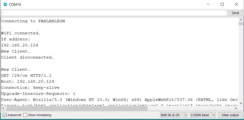
ESP 32 + Web Server + LED
One of the features of the XIAO ESP32-C3 is that it can be connected via Bluetooth or Wifi. In this project you’ll create a standalone web server with an ESP32 that controls output (one LED) using the Arduino IDE programming environment. The web server is mobile responsive and can be accessed with any device that as a browser on the local network. We’ll show you how to create the web server and how the code works step-by-step. You can find more info here
Here you will find the programming to use a Web Server with a LED. Here you can find the Arduino file to download. Below you can see a video of how it works.
When you have uploaded the code, you should open the Serial Monitor to see the IP address that you will have to copy to paste into a browser.
Files
Find below the files that I made for this project.