Final Project
Project Digitialzing Arm
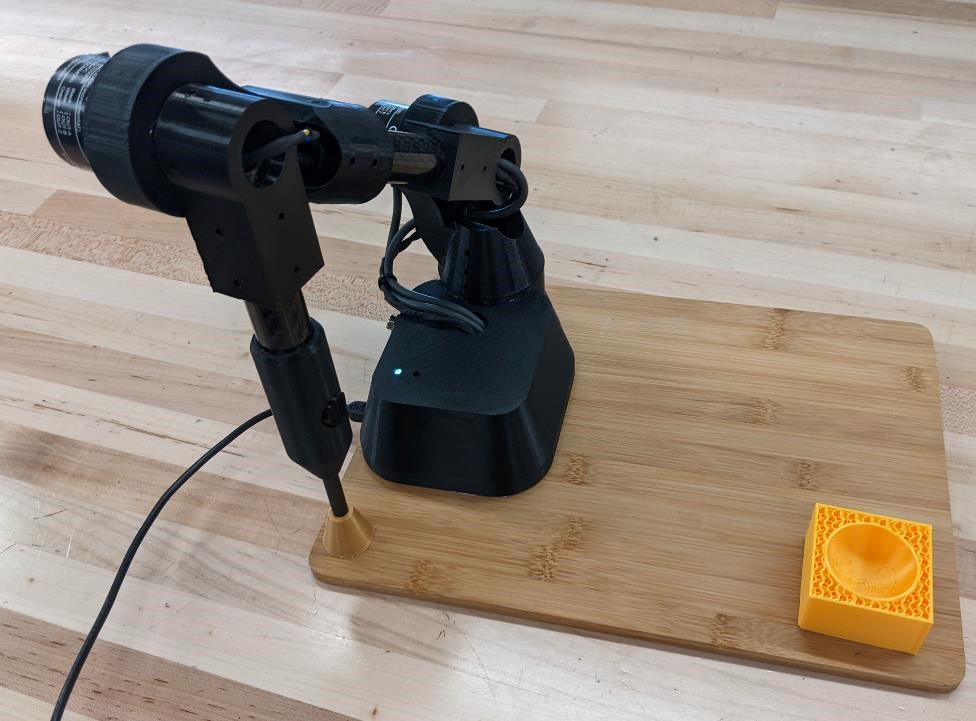
A digitizing arm for metrology and reverse engineering.
Final Project Slide
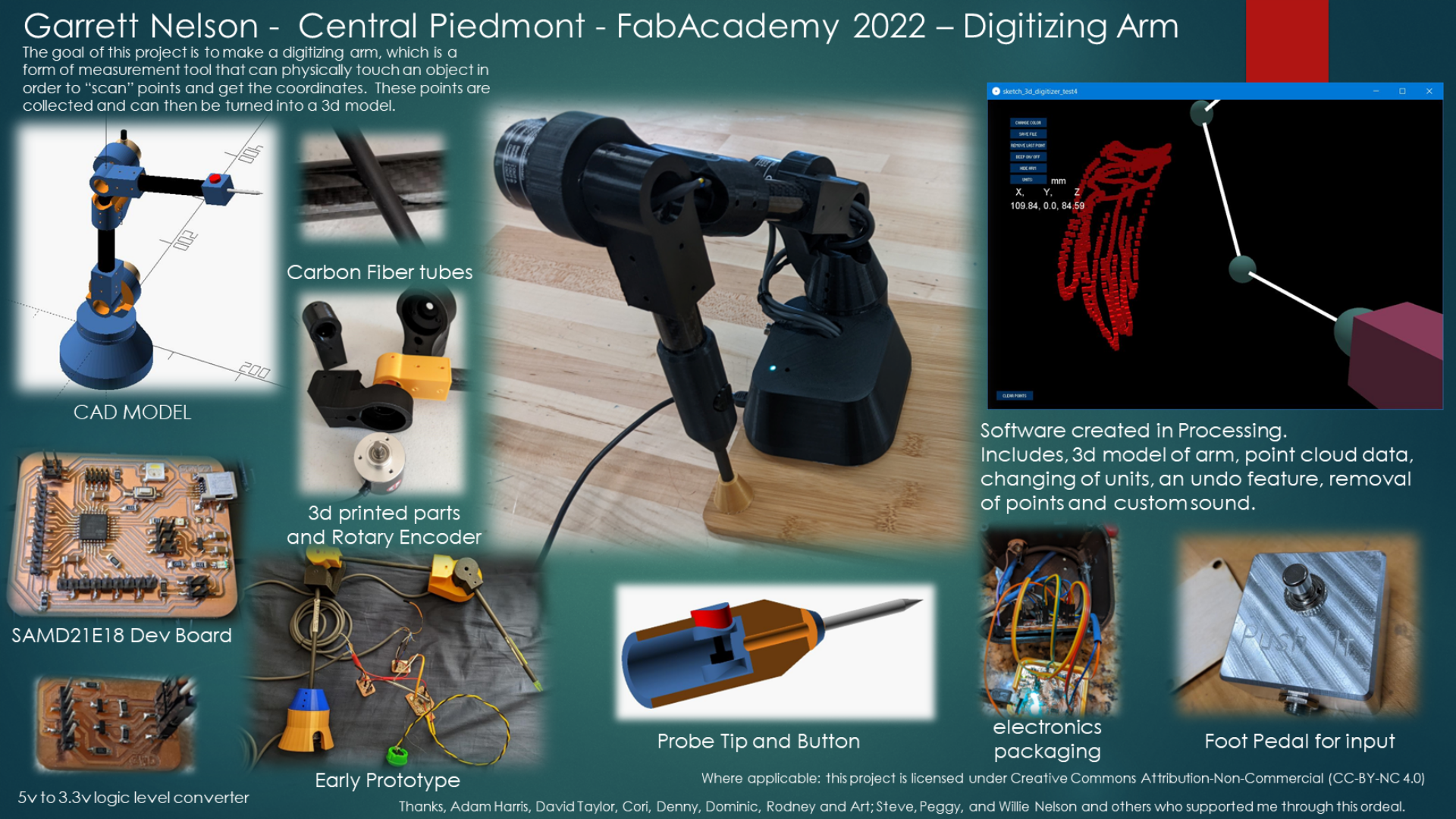
Final Project Video
For More Information…
Much of the information about this project is contained in worklogs. I write too much, and if I didn’t keep this information on another page, this page would become enormous, unmanageable, and unreadable.
So please look at other pages for more detailed information on different aspects of this project, such as the electronics, software, prototyping, etc.
Here are some key worklogs for the final project that contain more details:
Week 1 Worklog. This week is very early design and prototyping.
Week 15 Worklog. This is the week with information about the SAMD21E18A board that I designed and built for this project.
Week 16 Worklog. This is about installing circuit python on the SAMD21 board.
Week 18 Worklog. This week looks at reading quadrature encoders, logic level converters, dealing with design flaws in the SAMD21E18 board, as well as writing basic arduino code to read the encoders.
Week 19 Worklog. This week is all about the final project and contains a lot of details about the software used, looking at many of the early versions and I want I was learning/debugging as I went.
And the questions and answers pages from the last two weeks on the final project:
Week 17 - Final Project Questions. Answers questions about the final project
Week 19 - Project Development. More information about the final project.
Introduction
I’ve been interested in metrology for a number of years now. I find the precision and accuracy needed to build high quality parts, and to ensure that they meet stringent requirements fascinating. A modern method of measuring parts is using a Coordinate Measuring Machine (CMM). CMM’s are highly accurate, but also highly expensive. They’re common in the manufacturing world and labs, but less common in small shops. I would like to create a small digitizing arm that can be used to accurately measure and reverse engineer parts.
There are two common types of CMM’s. One is a typically gantry style, that looks very similar to a wood router. Instead of having a spindle that cuts, it has a probe that touches and takes measurements of the specimen. The specimen is placed inside the CMM and measured within. This makes the CMM limited to the extent of the part that can fit within. They are usually built on granite surface plates, use air bearings, and move in a cartesian coordinate system (X, Y, Z plane). The sensors are glass scales. They are high accuracy, but are permanent installations (most require air compressor, some now do not require air.) with a high weight (they’re built on granite surface plates.) and high cost. ($70,000 and up.)
The other form is an arm style (sometimes referred too by a “Faro Arm” (though Faro is manufacturer of this arm.) This is a kinematic system that looks more like an industrial robot, with arms that have multiple degrees of freedom. Digitizing arms are more flexible in what they can measure, are typically based on rotary sensors and polar coordinate system. They typically have a low weight, the ability to be transportable, and can be moved while in use so they can be used to measure very large objects such as cars. Their accuracy tends to be less than a gantry style CMM, but they also cost less ($8000 and up.)
This project is designed to build a digitizing arm, and to see with a relatively small budget, how accurate they can be made. High accuracy is unlikely, but I consider this a learning enviroment, and from starting we can build a higher accuracy arm.
Digitizing Arm
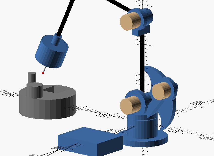
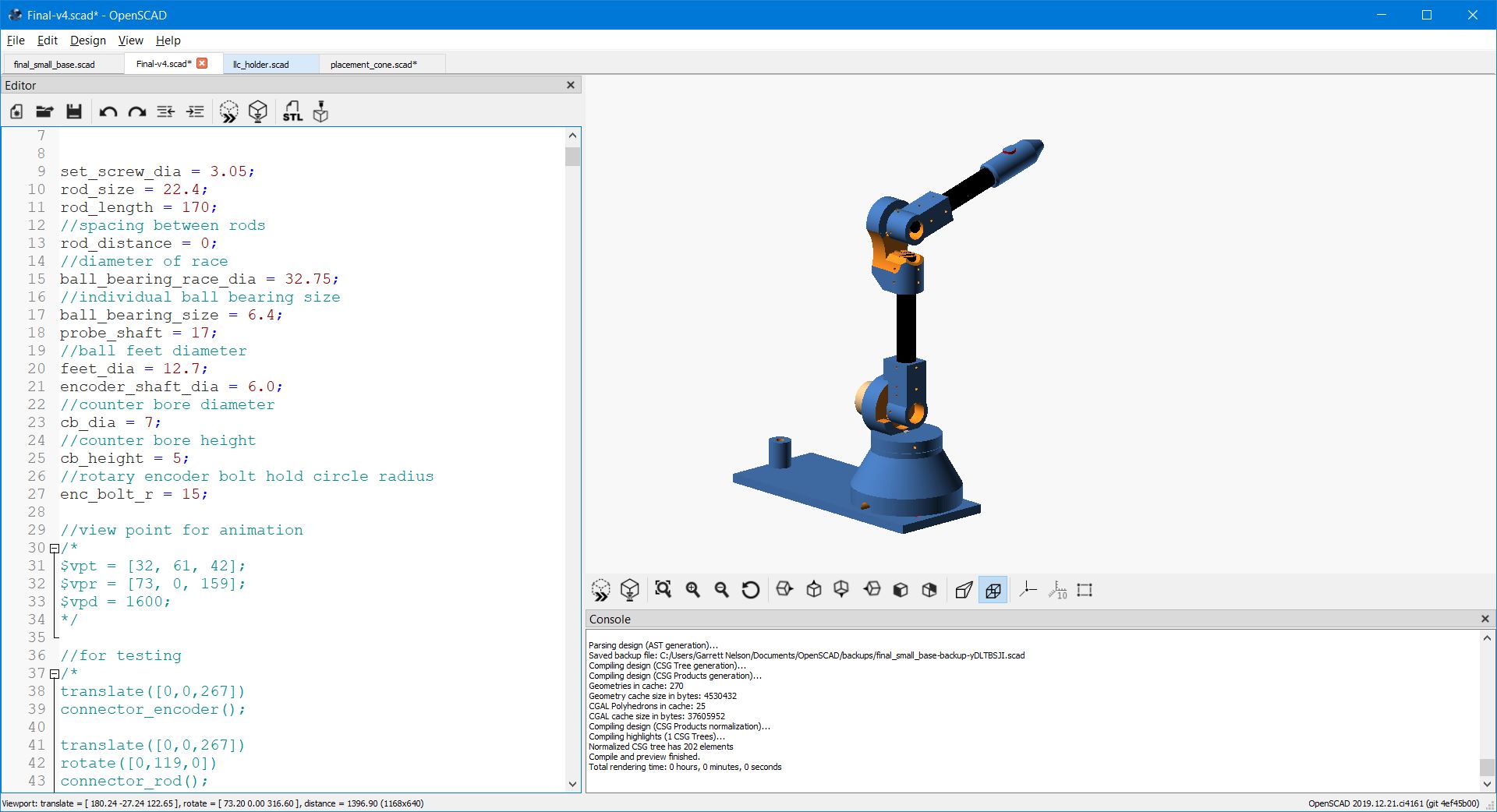
Rough Sketch
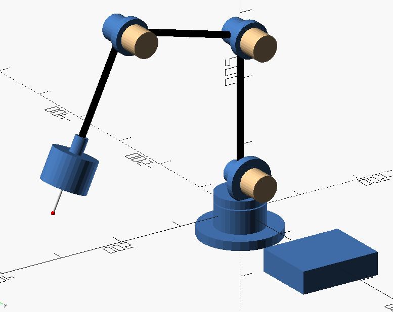
Shown: Blue = printed part, beige = Omron Rotary Encoders, Black = Carbon Fiber rods, probe and probe stylus shown at the end of the connected rods. Blue box on side is to hold electronics and the interface. 3d sketch made in OpenSCAD. Really ugly OpenSCAD code for this part can be found here: Arm
Design
This digitizing arm consists of 3 arms, each connected by a moveable joint attached to a rotating base, and with a touch probe attached to the end of the last arm. The joints are connected to quadrature rotary encoders which give an angular position of each joint. There is also a rotary encoder in the base, which allows for the rotary position of the arm to be captured. Finally, there will be a probe that detects any contacts with the part being measured. The data will be captured by an Arduino or similar microcontroller, and sent to a computer in order to capture a point cloud, that can then later be turned into a 3d model.
The arms will be created from a 0.300” (7.65 mm) carbon fiber arrow shaft. One of the benefits of carbon fiber is not just it’s stiffness and strength, but also, it’s low coefficient of thermal expansion.
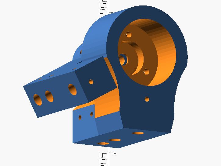
The arm connectors will likely be 3d printed, and will consist of two pieces for each arm. One piece will hold the encoder, as well as connect to the previous rod. The other part will connect to the shaft of the encoder, and attach to another rod for each subsequent arm.
The base of the unit itself will consist of multiple 3d printed parts, and possibly a laser cut/machined wood base. This will have a fixed stand, with another encoder attached. The encoder will support a plate that holds the first arm rod, and the encoder for the arm. It will likely need an extra and larger bearing of some type around this entire base to help support and smooth the rotation of the arm. This is due to the weight of the entire arm being supported by the encoder without the extra bearing.
There will be a small probe tip placed at the end of the arm to contact the part.
Finally, there will be an electronics enclosure that will have the wiring from the probe, encoders, etc. going in, and have the connection to power and/or computer coming out. This will either be 3d printed or laser cut out of thin plywood (maybe even machined.)
Design Goals:
This unit will be designed to be accurate, repeatable, and inexpensive. I also want the unit to be sturdy, and to be able to take abuse from inexperience users. The unit needs to have an accuracy of 0.006” (0.150 mm) or greater, and a repeatability of 0.003” or better. These are actually fairly stringent for a digitizer arm, and even more so for a DIY arm. However, this is a target, and in reality, if I can get anywhere near these goals, I will be happy.
In order to reach these goals, I’ll have to ensure that the stiffness of the arms, base and all the connections are very rigid. Any flex can be a major source of error, and with multiple connections, the error of one connection will be magnified to the next. Carbon fiber rods will help, but the 0.300” diameter may not be large enough over the given length. This is also a reason to keep weight down to a minimum on the end of the arm. The most likely issue will be the 3d printed connectors and the base of the unit. Because of their being made of plastic, they’ll need to be well designed and printed with large infill. Even this may not be enough to ensure their rigidity.
In order to maintain repeatability, especially if the unit is being moved, I will try and avoid using any wood in this project due to its high propensity to be influenced by humidity and temperature. Plastics can also be affected by humidity, but not to the same extent as non-stabilized wood you’re typically use for this type of project.
Designs and Prototypes
The below are images of some of the different design iterations of the project.
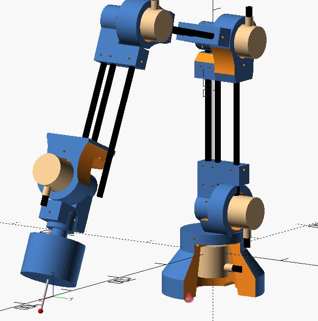
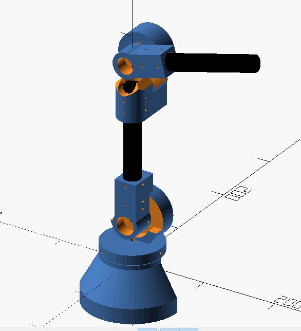
This design is getting close to the final design.
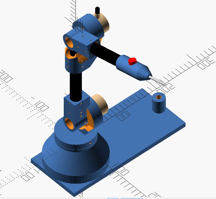
And the First Prototype
Notes and Challenges for Arm
While designing this part and sketching it out, I thought of a number things, such as:
-
The encoders are incremental encoders, not absolute, this means that every time power is disconnected, they “lose” their position. This means that they will need a “home” position that they return too and start from every time this arm is turned on and used. This isn’t the worst thing, but this is something that has to be taken into account when designing the arm and base (creating a known ‘home position’.)
-
Further, the length of the arms and starting point of the angles of the arm will need to be known to a high level of accuracy in order to calculate the trig and convert the polar coordinates into accurate cartesian coordinates.
-
Will need a good way to keep base down. High weight is obvious, but would like to keep weight down. Large flat base would also work, but would cause issues with usage. Could always bolt it to a surface plate, but that makes It less portable. Maybe suction cups? Good old C-clamps?
-
Rotary Encoder wires are about 5mm in diameter with sheathes. Won’t fit through current small diameter carbon fiber tubing. Would need to invest /re-engineer for much larger tubing. The wiring is going to be very unclean. I could make a sleeve around the entire part to hide wiring, but this is a less elegant solution, but probably best solution given constraints. I’m going to go with 22mm tubing.
-
Design currently relies on the internal bearings of the Rotary Encoders for movement. This could cause multiple issues. First, relying on these bearings to support weight of the entire system. Second, relying on bearings (which retain the encoding wheel in precise position) could cause movement of wheel and thus inaccuracy of measurements. If we switch away from rotary encoders (optical mouse sensors), then we need to add bearings.
-
Adding the above bearings of rotary encoder may increase weight. The bottom base, x-y encoder is likely to need a larger bearing for support to keep it from leaning.
-
The specific Omron encoders are now very expensive, at around $500 for a 1000 ppr (pulse per revolution, essentially a measurement of resolution.) It’s likely I will use a cheap Chinese knockoff of these style optical encoders that are closer to $30 a piece.
-
The probe on the end of the arm is currently very large based on prototypes. To be more useful, (to fit in smaller areas without the probe body getting in the way) it would be necessary to shrink the probe body. I have gotten rid of this probe and installed a simple stylus with a button.
-
Moving the probe tip is a large issue. First, simple probes are moved in 1 axis at a time, and this allows easy interpolation of point. With multi-axis/polar movement of probe, will be much more difficult to determine where the probe tip actually makes contact. With cartesian CMM’s, probes usually deal with multi-axis movement by the direction they retreat from the part after triggering probe sensor. This movement after the probe goes back to un-triggered helps the software determine which way to compensate for the probe tip. This solution, however, requires better programming skills than I have.
-
I’m really bad at trigonometry.
Other Challenges
Software, software, software. I can not program, so the idea of getting the data from the arm into software is an unknown for me. And to be able to accurately capture this data in order to turn it into a 3d model map seems incredibly difficult to me. In the same vein, this is not an cartesian coordinate system (XYZ) with fairly simple way to determine location, but rather is going to require an understanding of kinematics and polar coordinate math. Yikes!
There are going to be questions concerning the mechanics and geometry of the arms. May require offsetting arms side to side. Need to make sure there is no slop in bearings (regardless of using encoders for the bearings or not.) Also, the strength of 3d printed parts to not allow flex of the arms. All of these will can create inaccuracy.
Time. Not a lot of time to get things done in this class. I have to make sure I can get something done in the time alotted. This means somethings I would like to do, I won’t be able to do. I’ll be forced to make shortcuts.
Finally; unknown unknowns. I don’t know what I don’t know yet. And I don’t know a lot.
Manufacturing Processes
3d printing is an obvious large part of the physical parts of this build. The most likely parts that will be 3d printed are the rod and arm connectors, the swivel base, some of the touch probe internal parts.
There will also be CNC machined parts (most likely made from Aluminum or steel). Especially the base of the unit, and the body of the touch probe. Some of the internal and precise touch probe parts will likely be machined from plastic, as 3d printing may not afford the necessary tolerances.
The electronics will be based around a modified arduino board and/or Attiny85 boards, and be milled out of copper clad pcb. I’ll be soldering them and preparing them to be connecting to the sensors as well as one another.
The sensors for the arm positions are based off rotary encoders, but I am most likely going to attempt to create other sensors to replace/accentuate the rotary encoders. The sensor for the touch probe is going to be a kinematic, mechanical switch.
The output will be data that is sent through both an LED’s (for a “touch” on the probe tip). The data of the touch, and relative location of the probe will be displayed on an small LCD.
The data for the arm position and probe points will be output to a local computer, where it will be translated via software into Cartesian coordinates and mapped into a 3d environment as point cloud.
Material and Parts:
DIY parts:
Many parts can be 3d printed and CNC milled.
- Base, arm connections, encoder holders, probe section, etc.
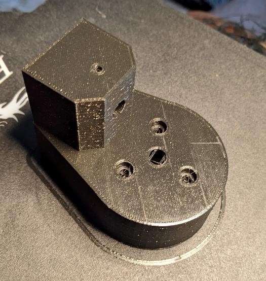
Prototype of the encoder and rod holder. (For more info, see Week 1 Worklog)
Prototype of the ball bearing print. I used POM ball bearings, and this worked better than I expected. (I was expecting it to be rather rough. And it was, but it wasn’t the worst ball bearing I’ve seen.)
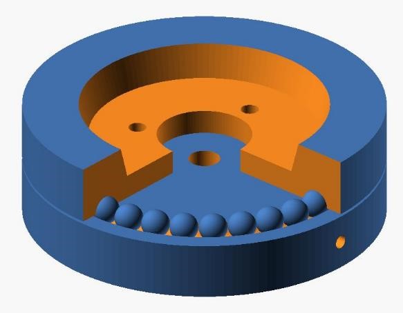
(For more info, see Week 1 Worklog and Week 3 Worklog
I would have liked to create my own rotary encoders, however, I just couldn’t figure out a good enough way of doing so with the necessary accuracy/repeatability to make it worthwhile.
Off the Shelf Parts:
For the Digitizing Arm:
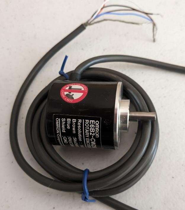
- 3 Omron Incremental Rotary Encoders 1000 ppr (E6B2-CWZ6C) (I have 2 of these, I’m 99% sure they’re counterfeit. I bought them off ebay a few years ago for about $30 each. A google search just revealed they are being sold for $530 from Newark.) https://www.ia.omron.com/product/item/2450/
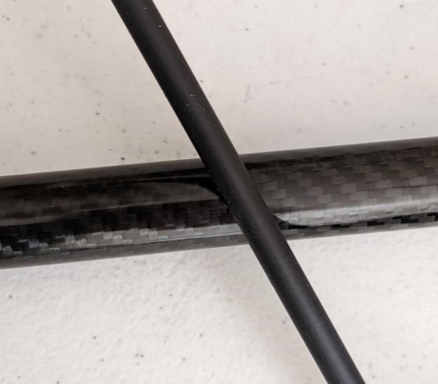
- Carbon Fiber Arrow Shaft (0.300” (7.65mm) diameter, 31” length)– cheap after hunting season.
- Carbon Fiber 22mm Tubing
- 50 POM ball bearings (for ball bearing system on base.)
- assorted hardware, set screws, nuts/bolts (30 m3 x 8mm SHCS, 20, 6-32 x 1/8” set screws).
Here’s an image of the basic “Omron” encoder (it’s counterfeit), and the arrow shaft compared to a 22mm carbon fiber tube.
BOM
And the BOM and Cost for this:
For the Mechanicals:
| Part | Description | Quantity | Cost Each | Total Cost |
|---|---|---|---|---|
| Carbon Fiber Tube | 1 meter, 22mm diameter | 1 | $30 | $30 |
| Rotary Encoders | Omron E6B2-CWz6C | 5 | $25 | $125 |
| POM Ball Bearings | 1/4” pom balls | 100 | NA | $12 |
| M4 bolts | 12mm long | 30 | NA | $5 |
| M3 bolts | 8mm long | 30 | NA | $5 |
| PLA filament | physical elements | around 250 grams | $20/kilo | $5 approximately |
| 2” x” 2” x 3” aluminum | for foot switch | $10.00 | $10.00 |
For electronics:
I’ll be using a SAMD21 board I designed, as well as a logic level converter board.
| Part | Description | Quantity | Cost Each | Total Cost |
|---|---|---|---|---|
| SAMD21E18A | microprocessor | 1 | $4.30 | $4.30 |
| 10uF Cap | 1206 | 2 | $0.04 | $0.08 |
| 1uF Cap | 1206 | 2 | $0.04 | $0.08 |
| Green LED | 1206 | 2 | $0.05 | $0.10 |
| WS2812B | Neopixel | 1 | $0.50 | $0.50 |
| 330R resistor | 1206 | 3 | $0.02 | $0.06 |
| 10k resistor | 1206 | 3 | $0.02 | $0.06 |
| 1k resistor | 1206 | 1 | $0.02 | $0.02 |
| 0R resistor | 1206 | 1 | $0.02 | $0.02 |
| LM3480-3.3 | SOT-23 | 1 | $0.42 | $0.42 |
| USB B Mini Connector | SMD | 1 | $1.02 | $1.02 |
| Pin Headers | Various | 42 | $0.01 | $0.42 |
| Button Switch | PTS636 smd | 2 | $0.16 | $0.32 |
| Stomp switch | momentary | 1 | $2.50 | $2.50 |
| 1/4” jack | 1 | $1.20 | $1.20 |
Mechanicals
As show earlier, I first created a prototype that would help me work with the software applications first.
This was a very basic design that had a 7.65mm carbon fiber arrow shaft I had laying around that I then use to test the software. It was incredibly helpful in getting the software to work. I would have a thousand times more difficulty with a test prototype.
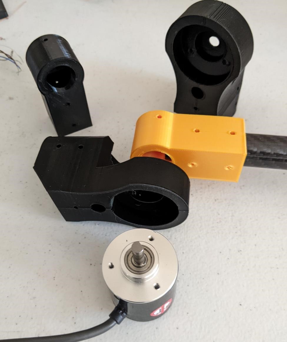
Here are some of the 3d printed parts to hold the carbon tube and encoders together.
and here is how I’ll be dealing with the cables: Usinb Carbon Fiber tubes
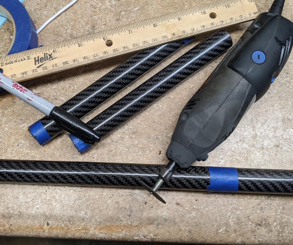
And cutting the Carbon Fiber Rods. This is a very messy step, and carbon fiber is very nasty, so wear proper personal protective equipment (very close fitting safety glasses, a good dust mask, gloves) when doing this. That includes love sleeve shirt and long pants.
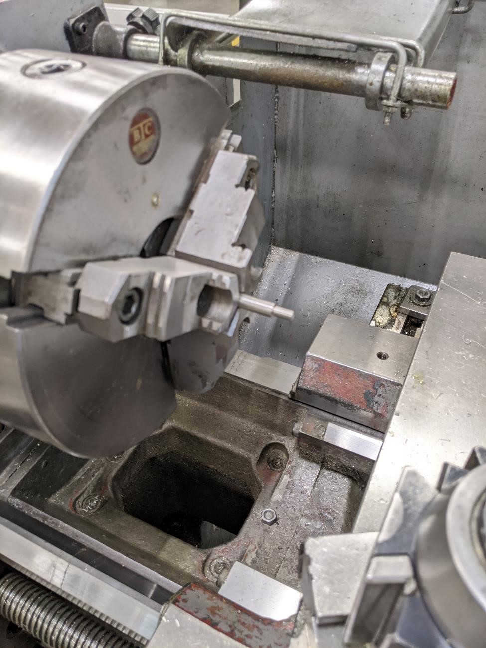
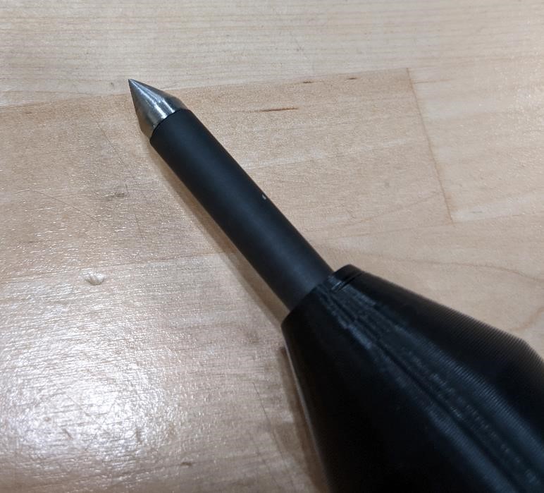
I also made a small tip for the probe out of stainless steel using a manual lathe.
and it turned out nicely, if a bit too sharp. (second version I will be rounding this tip more.)
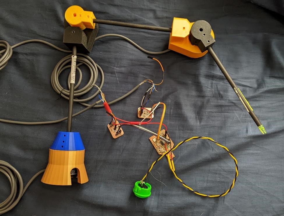
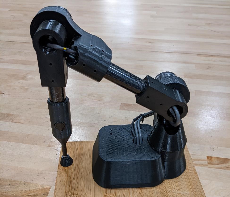
Putting it together…
The other aspect is putting all the disparate components together to create a working project.
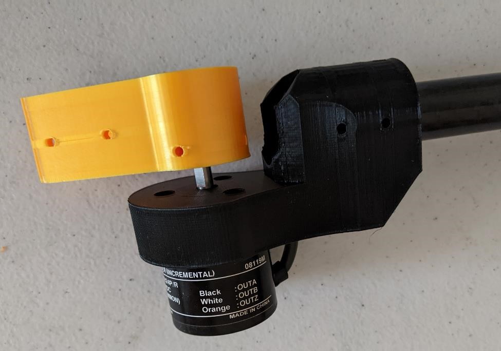
I started with the Carbon Fiber Tube and 3d printed parts and started putting these parts together with the rotary encoders
And these were all put together. The encoders were held on to the arms by 3mm (or 4mm, I forget) 8mm long bolts.
Then the carbon fiber was cut as mentioned above and held in place with small grub set screws (I actually used 5/16” set screws since that was what I had on hand at the time.)
I then would have a small base/case that I would put the electronics into, and a small bamboo wood board that everything would mount on to.
This was a rather simple process. The difficult part was wiring evertyhing together and making it nice and neat.
Electronics:
There are 3 rotary encoders, which require multiple inputs due to quadrature setup. (maybe more if we use the 1 rev counter, which I would like to use as it could be setup as a origin positon). The plan was to use an Arduino clone with an atmel 328p, but I had problems getting it to work, and Neil warned us from using them.
The probe will have at least 1 signal connection, and possibly 3 if two buttons are included. These will be also connected with the board for signal connection.
I originally wanted to use Attiny85’s (and then Attiny412’s) to be on each encoder, and then send the data to a mainboard over i2c. I liked this option for a number of reasons, however I could never get the attiny412’s interrupt to work. I don’t know what the problem was, but after a few days of struggling with this, I moved on. You can read all about my struggles with the Attiny412 interrupts in worklogs.
I then moved on to the SAMD11. However, I quickly found out that this chip may be powerful, but the lack of memory on it with the arduino bootloader made it almost useless.
I however did find it useful for some of the early testing with the rotary encoders. I was able to get it to work first with 1 and then 2 encoders. However, I quickly hit the limit of the memory as well as the number of accessible pin inputs, so I moved on to the SAMD21.
Early electronics work
Here are some of the earlier prototypes for the electronics. Even though none of this ended up working, I feel like I should add it here as a lesson in what not to do when starting a project like this. I wish I had known more about what the approrpriate chip and application to use was first, and then move on from there.
See Week 13 for more information on Rotary Encoder Sensors and the boards
See Week 14 for more information on the network system that will send sensor data over i2c. This however ended up being deprecated.
This was the plan at one point: Each board would be connected to an encoder and send the signals further up the chain.
And here are some images of the SAMD11 board I had made and used as a development tool:
First as a way to communicate with attiny412 boards in order to collect the data and then move it forward to the PC.
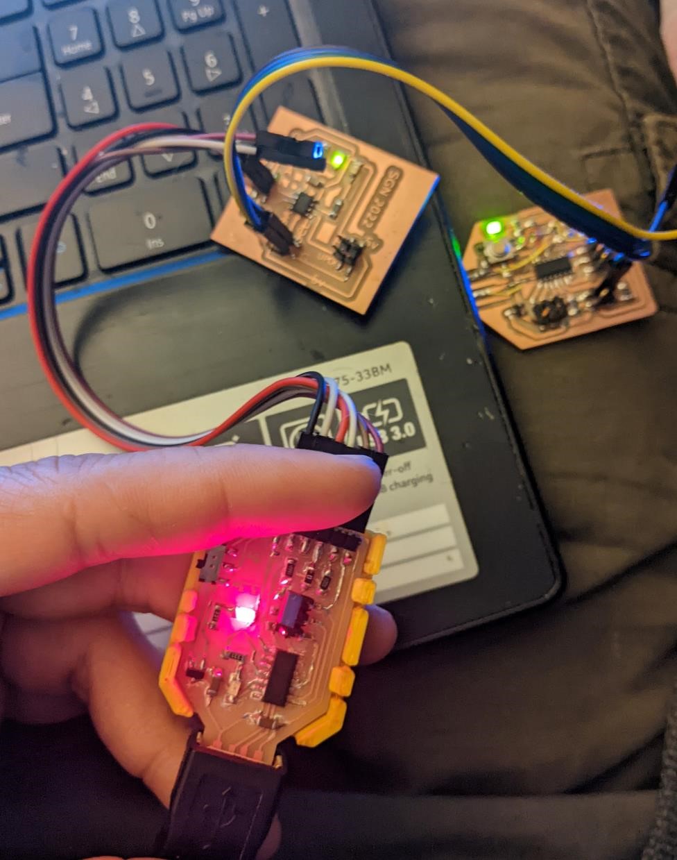
and then hooked up to two logic level converters and two rotary encoders:
Again, this samd11 board didn’t meet the requirements I needed, but it did provide a good testing rig at first.
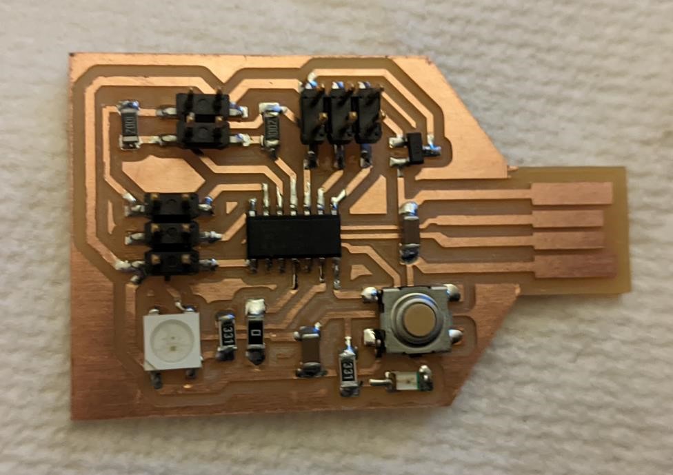
Building the electronics - SAMD21E18A
And I finally came across the final board that I’ll be using, a SAMD21 board.
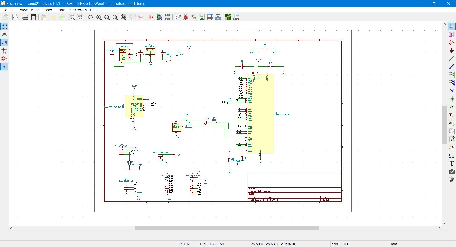
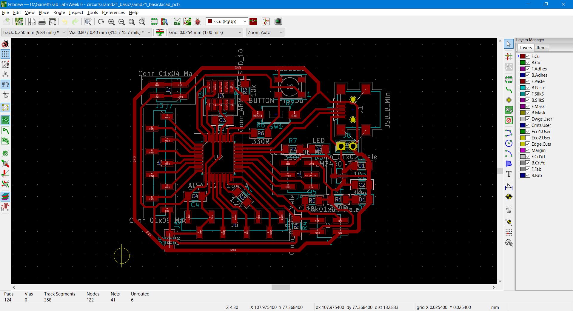
And here’s a quick view of the schmeatic and layout, but again, more detailed information on this can be found elsewhere.
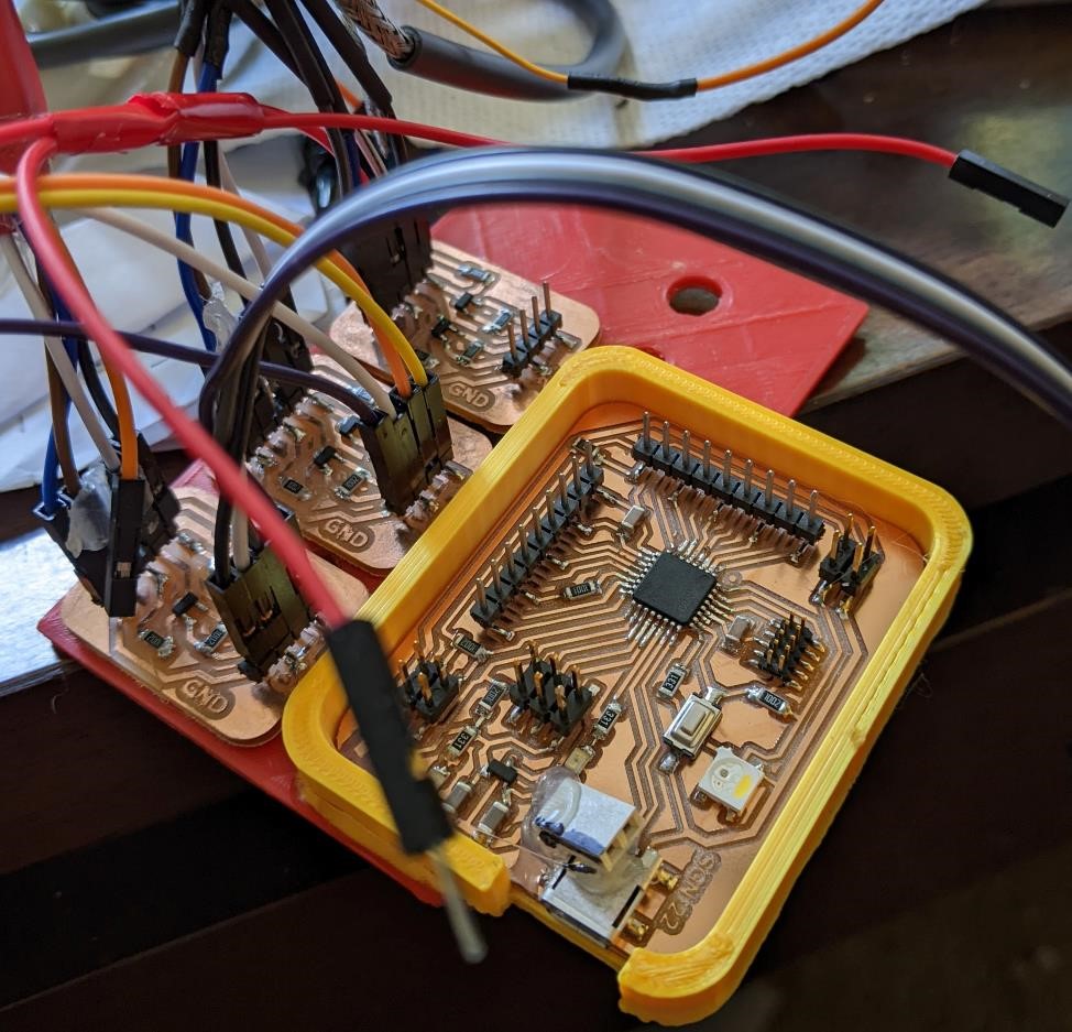
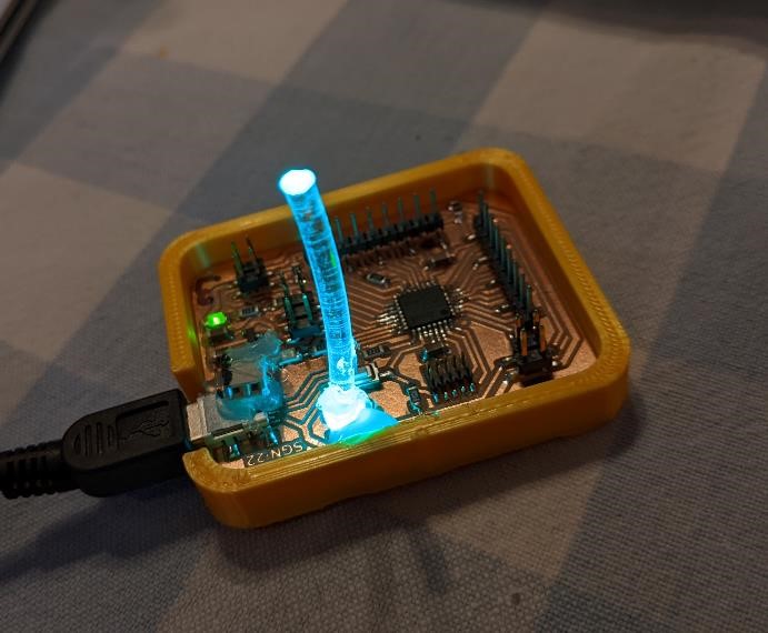
And the final board assembled:
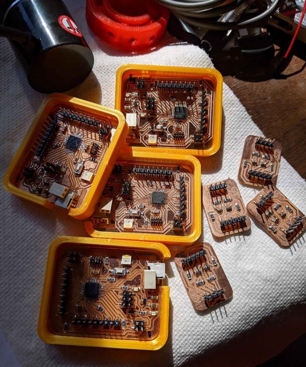 )
)
This is a board that is designed with a SAMD21, and almost all the pins broken out (with the exception of 1, which I regret not having done). It has an led connected to one pin, and a neopixel connected to another. It also includes a reset button, as it’s pretty easy to mess this board up when using the arduino bootloader if you’re not careful (and it defaults to using a crystal oscillator instead of the usb calibrated internal oscillator. Minor thing, but easy to miss in a hurry.)
The board information on making one, as well as installing circuit python on it can be found here: and here: Week 15 Worklog and here: Week 16 Worklog.
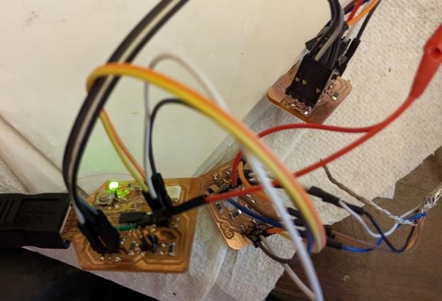
I also had to add logic level controllers since the rotary encoders used 5v to 24v (I powered them with 5v) and the samd21 cannot handle more than 3.5v (and apparently it’s pretty sensitive to this.) And so I created 2 channel logic level converters for each encoder (and the board files can be found in above worklog weeks).
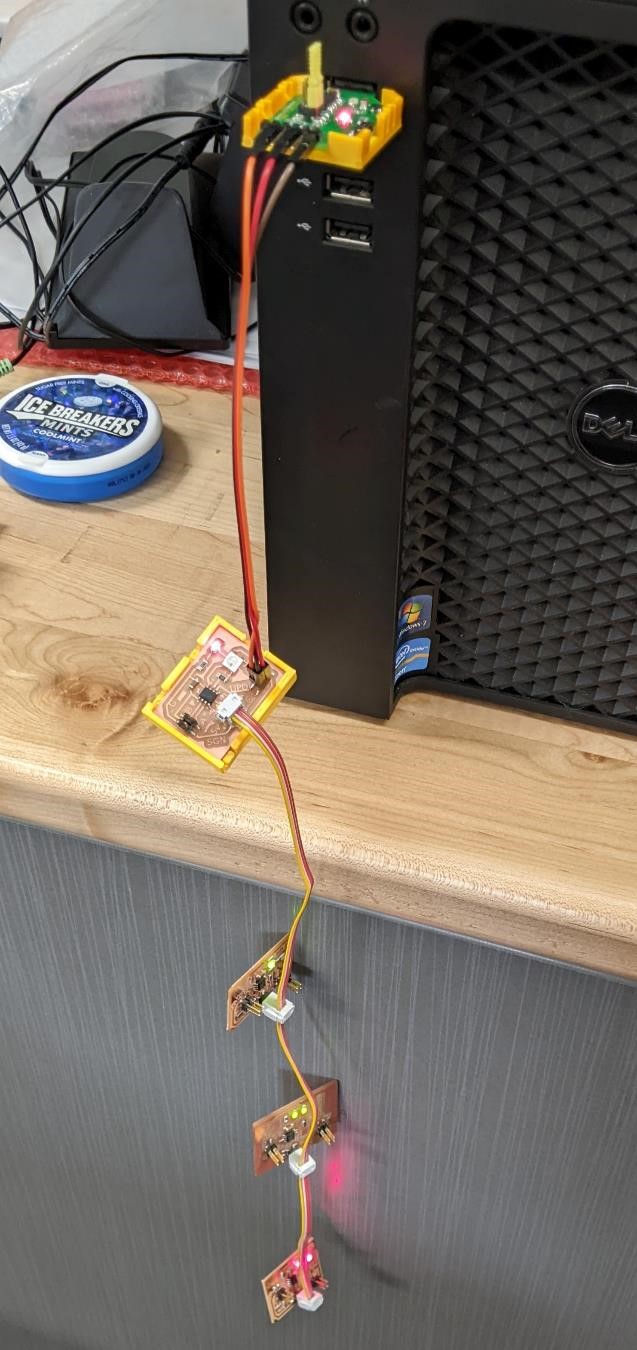
Integration
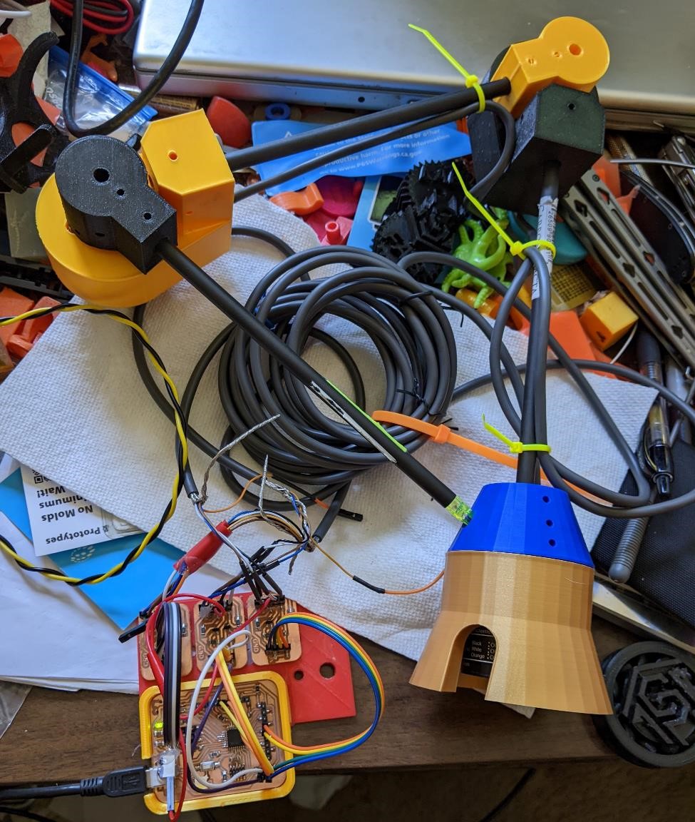
The next part was packagining.
I designed the arm so that the wires would flow the carbon fiber tubes, into one another, into the base. This worked really well.
However, the small case which housed the electronics as well as the wires, and making sure to have extra cable for any extra movement, strain relief (and also enough to package and unpack the entire system) made fitting everything in the case very tough.
I solved this by creating a small side board that held the logic level converters (which the rotary encoders directly plug into) by gluing them to the side of the case.
Each of the rotary encoder cables which had 4 cables (1 for GND, 1 for 5-24v, 1 for signal A and 1 for signal B) were ended with a connector and used heat shrink to protect any exposed wires plugged into these logic level converters, which then plugged into the SAMD21 board.
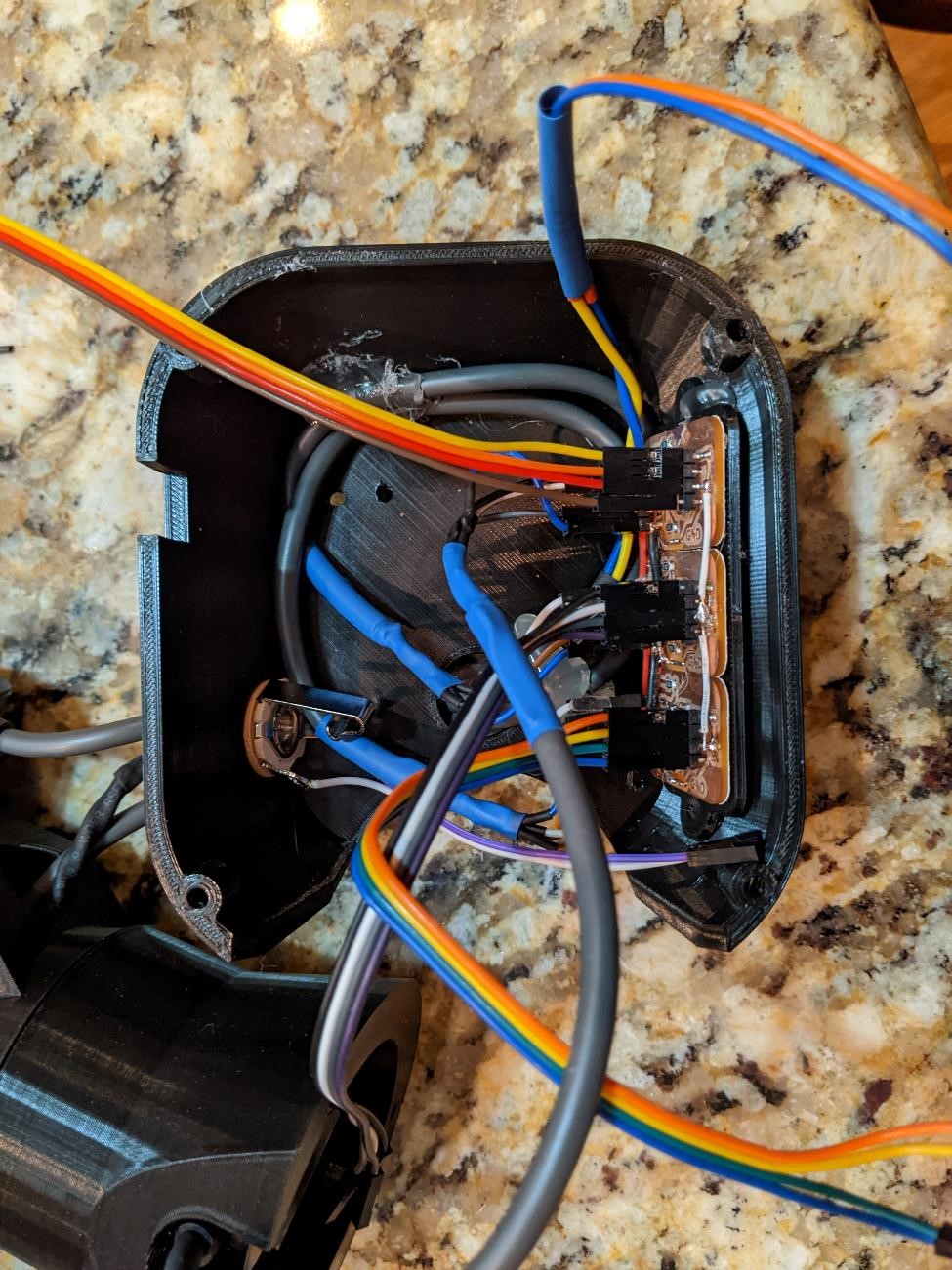
I then tucked extra wiring around the top half of the case, and the cables from the encoder went through a small hole in the top of the case into the boards.
This was all able to fit into the small base very nicely.
Once I had all of this tucked away, I was getting very close to finishing the physical project.
Other Input
While the rotary encoders are providing input for this entire system, I wanted a way to capture only specific points. Getting data into the system is done by a pushbutton control. I’ll (hopefully) have two pushbutton controls. One on the arm itself, and a foot activated one.
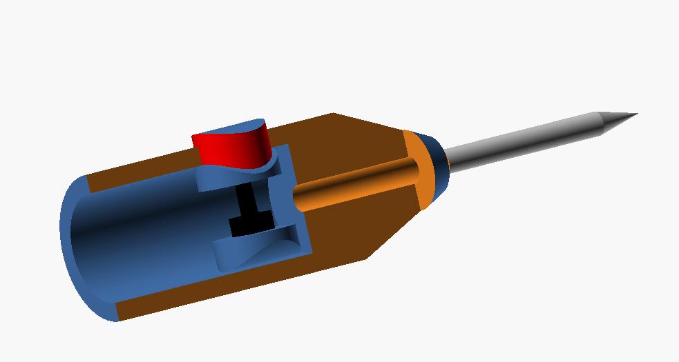
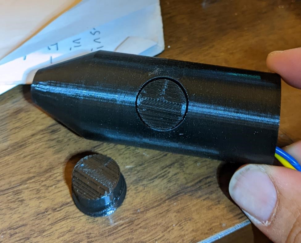
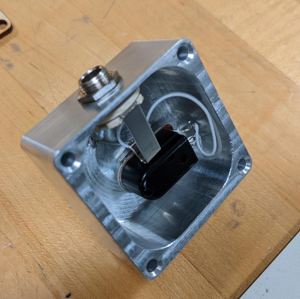
Here’s the design for the arm pushbutton. It has a small switch inside of the main probe holder, which can be activated as you are holding and using the probe arm.
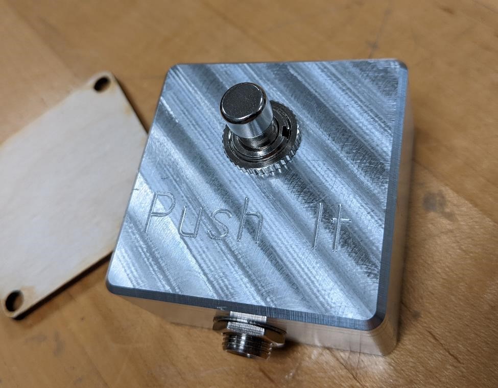
And then I also included a foot pedal in case you didn’t want to use the arm switch for some reason.
This was milled out of aluminum with a wooden base plate cut on the laser cutter. It has nothing more than a momentary pushbutton switch designed to be stepped on, and a 1/4” jack often used for guitar cables. This is connected to the SAMD21 board.
It was quite the tight fit of the getting the jack and switch in this relatively samll enclosure. I had to make sure that the switch wasn’t shorting out against the side of the aluminum box.
When either of these buttons is pressed, it sends a signal to the SAMD21 board that then forwards it to the computer. The computer will then grab the point at which the arm is currently located and save it to memory.
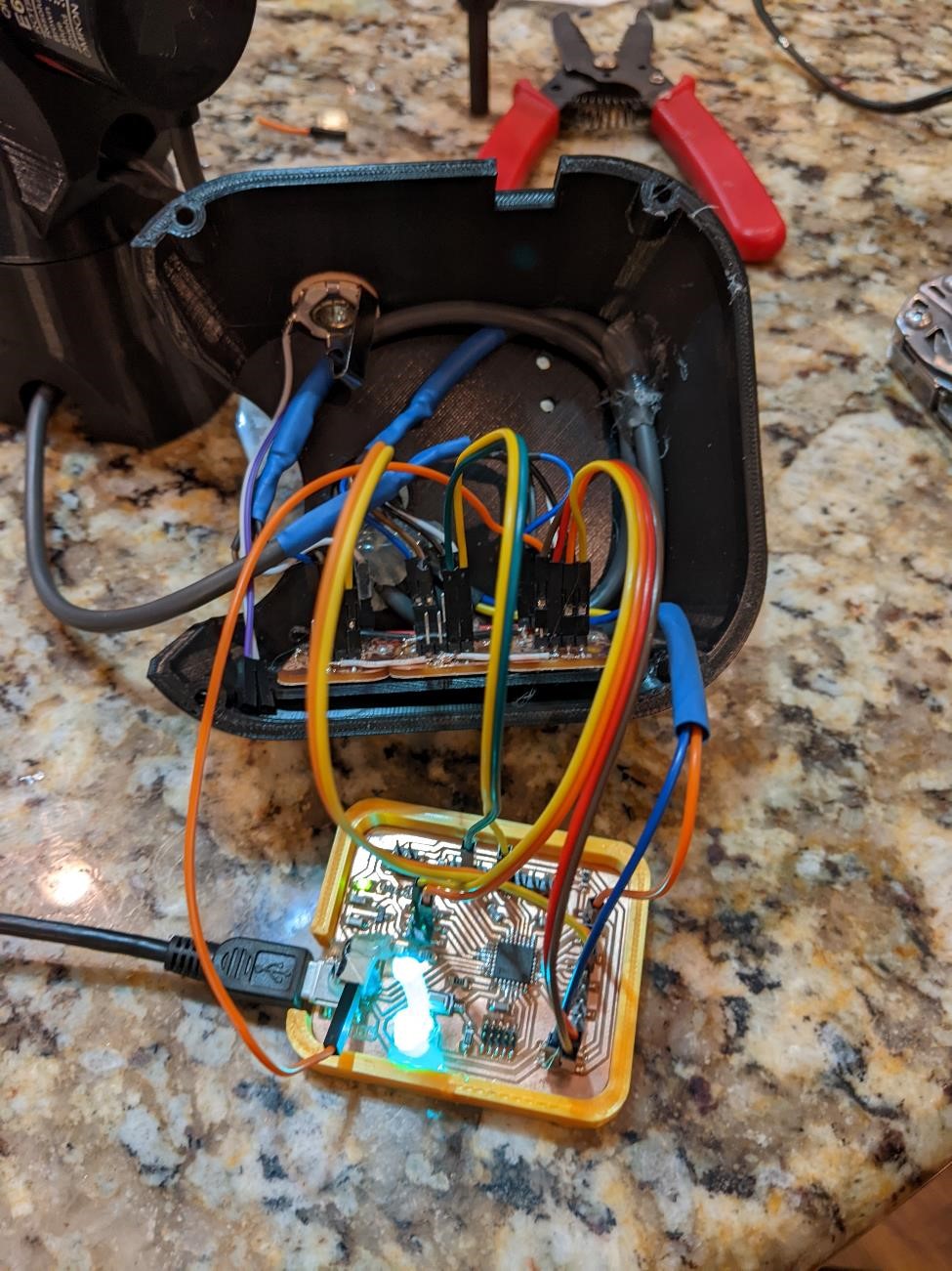
Output
The main output device is the computer software.
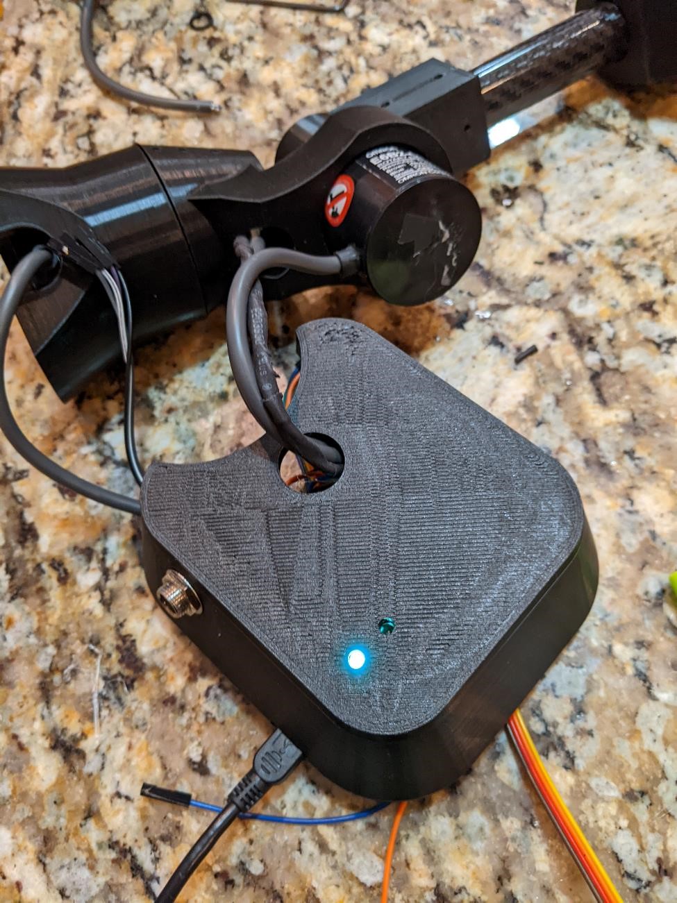
However, I’ve also included two LED’s, one of which is a neopixel. When the button is pushed to record a point, the neopixel lights up white to let you know that it’s taking a point.
The neopixel has a small lightpipe attached to it to send the light to the top of the case.
The other led is a status light that simply blinks when data is being collected from the rotary encoders.
But again, the main output is the software to collect data.
Sound
I also created a custom beep tone for when a point is triggered in the software as another form of non-visual information.
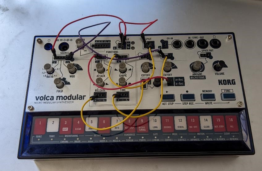
I used a small Korg synthesizer (called a Volca Modular) and created a number of possible beep sounds. I then curated through all of these using Audacity, and chose the sound that I liked the most.
I then selected this individual sound and saved it as a monoaural wav file.
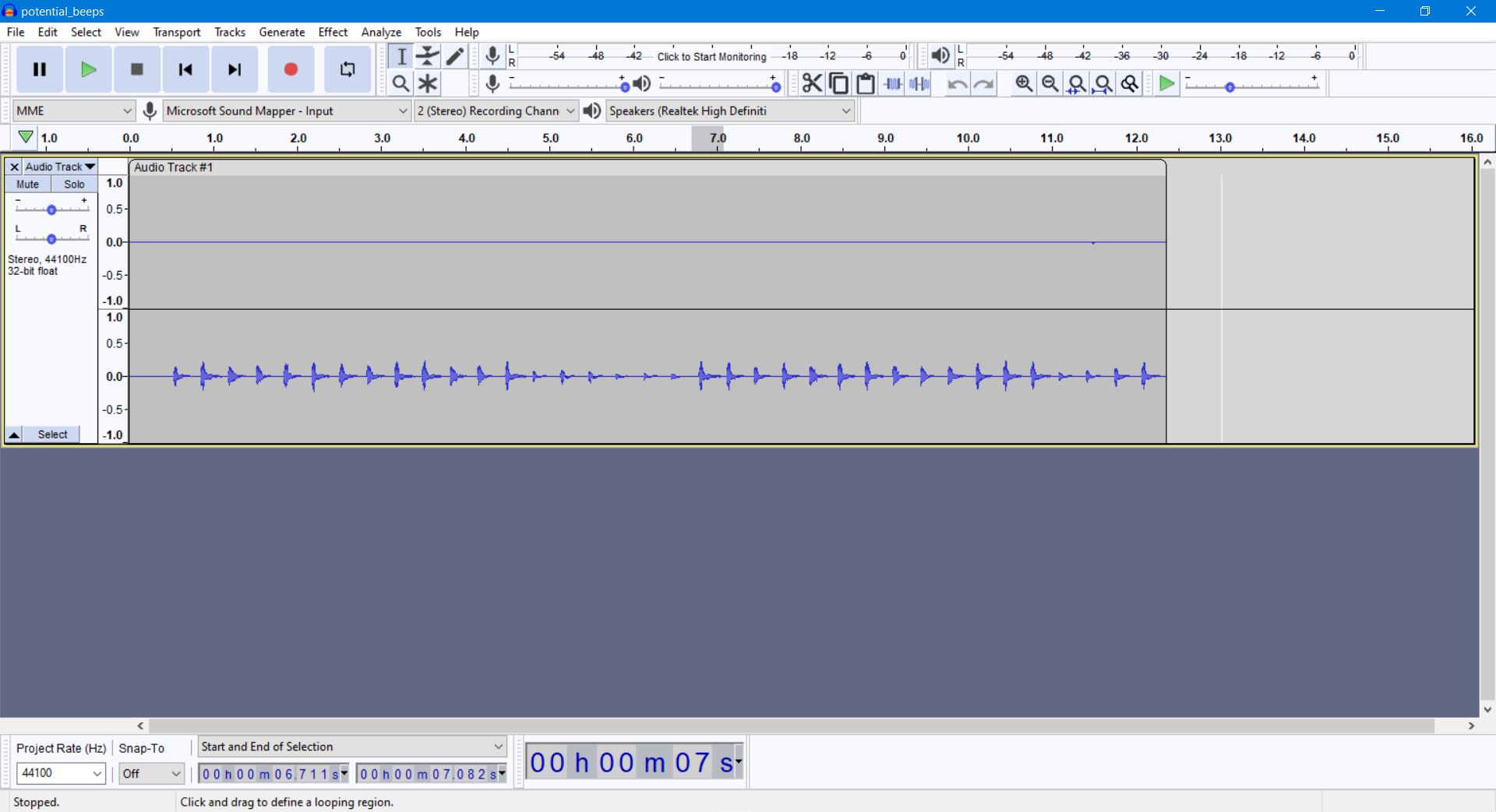
And here is the final candidate (I’m hoping this will work and you can play the sound here!)
Your browser does not support the audio element.
Yeah, that’s what I spent time doing. But it was fun and I got to learn how to play sound through Processing, which is a good segue into…
Software:
This was the hardest part of this entire project for me.
I struggled with the software for both the samd21 board as well as in Processing to collect and display the information.
A large part of the story can be found in the Week 19 Worklog.
Software design
I wanted the software to be able to take data from the digitizing arm and convert it to cartesian coordinates. As data come in through the connection, a button (either pushbutton for hand or foot.) software to grab the data from each of the rotary encoders, and their position. The software will then convert the data from the arm’s rotational positions for each joint of the arm (in a polar coordinate system) and then convert these into positions in a cartesian coordinate system. (That sounds easy! I have no idea what I’m doing!)
The data should then hopefully be able to be mapped into a 3d space and show the location of each “touches” of the probe and provide a representation of these in a 3d point cloud, that can then be used for further processing in other software.
When I started out, I had no idea how to do any of this.
The Code for SAMD21 board
The latest code can be found here: the latest version of the SAMD21 board encoder code (ino file)
The first thing I needed to do was to get code to collect the data, and send it to the PC. It sounds easy enough, but for this project I had to rely on interrupt’s in order to make sure that I was collecting each piece of data accurately.
An interrupt does what the name suggests, if it’s “triggered” it will interrupt whatever process/code is running, and it will run it’s own code, and then revert back to whereever the code was and the program goes on as normal.
I had a number of issues with getting this working. Again, refer to worklogs for more information. But I finally managed to get interrupts working and then I was able to start the actual programming.
I won’t go over every single piece of the code, but I’ll do a quick rundown of what the code actually does:
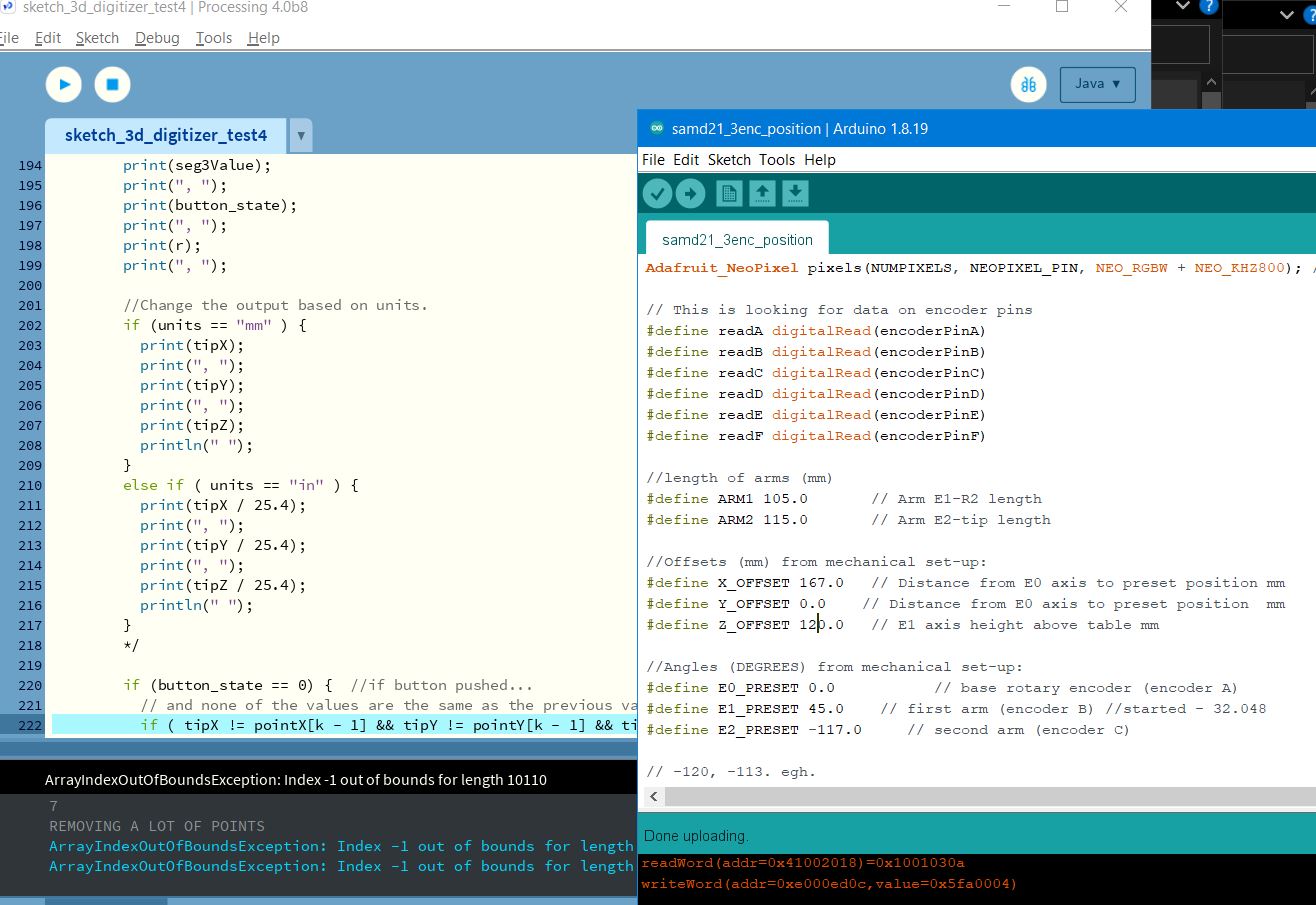
First, it labels a ton of variables that I’ll be using, as well as information about what pin on the board is connected to what (which encoder, the buttons, led’s, etc.) The code also has offsets (base height, arm length) and preset angles (how much is the arm bent at it’s origin position?) for the arm, so that the code can actually do the trigonometry and send the data of where the arm tip is located in cartesian coordinates to the PC. This data entails the
There are 3 encoder hooked up in this code. This alone means there’s a lot of duplication in the code.
Next, I start setting up all the processes that I’ll need.
I have to set up Serial, the Neopixels, The buttons, etc.
Then I have to collect all the data, and make sure that it’s converted into the right format for processing (from direct encoder readings into an actual angle measurement)
This was then put through trigonometry using Forward Kinematics in order to find the right angle for each part of the arm and determine how far the tip position of the arm was from the base.
This is a bit too much to get into here, but there’s more about this in the worklogs.
After that, this data, including the raw rotary encoder data, the button state, and the tip position is all sent over USB serial to Processing for the final output.
Software, more like It’s Hard-ware.
This was one of the more difficult aspects of this entire project.
I really struggle with programming, and this is what took me the longest time by far.
Using Processing programming
New version of software for processing (pde file) can be found here
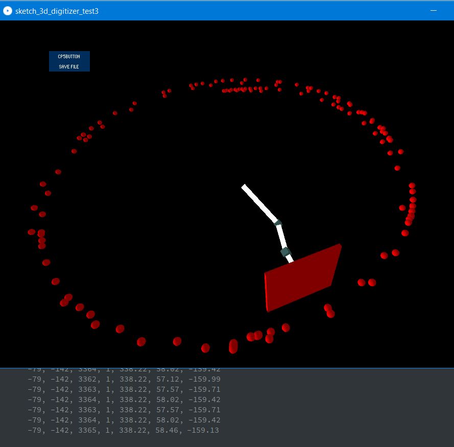
The below was my first 2d sketch using Processing that grabbed data from the encoders, used my samd21 board and sent it to a PC over USB serial, and used that data to display the position of the arms.
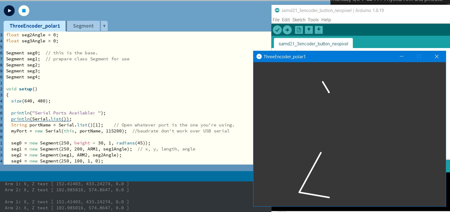
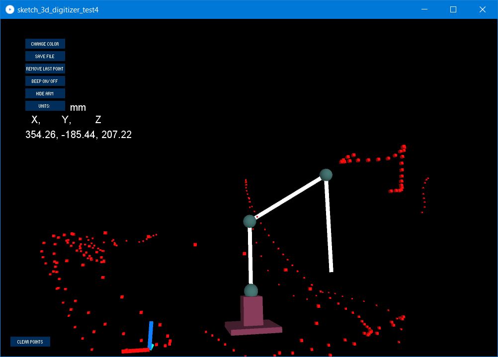
And then I moved on to working on an arm in 3d.
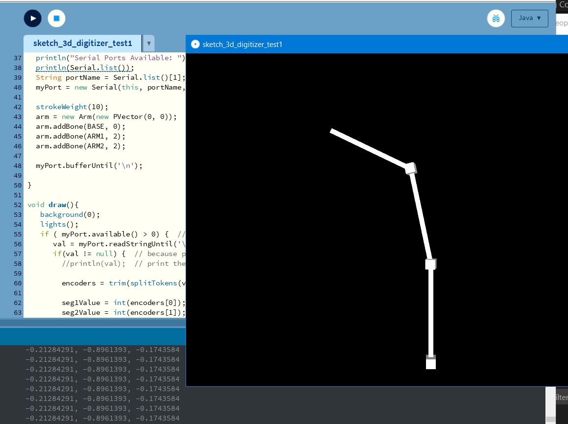
And I finally made a more and more detailed program.
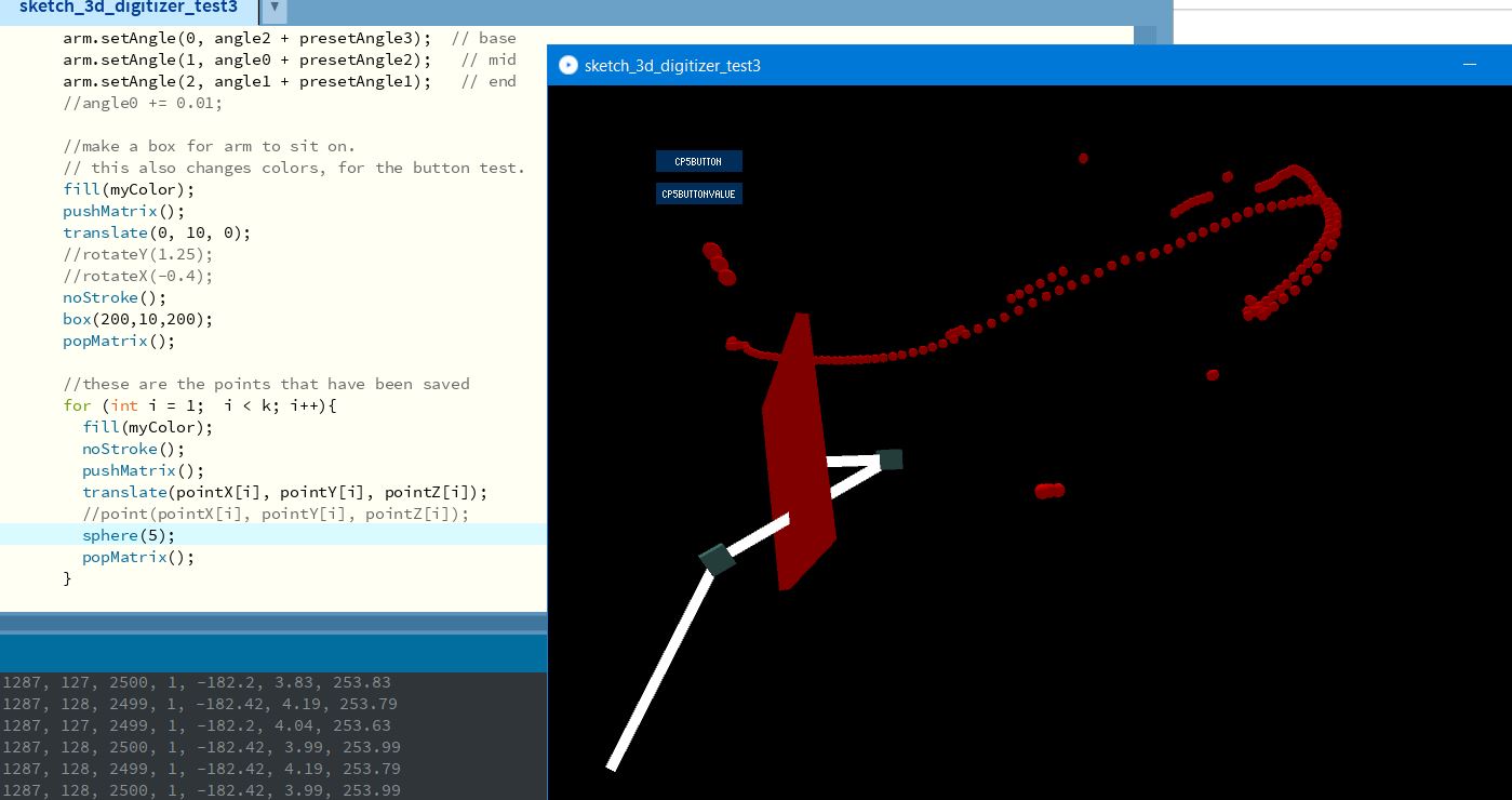
The final program can do a number of things, such as:
- Change the colors to better see dots
- Change the units (either metric or inch)
- Shows the X, Y, and Z coordinates
- Saves the X, Y, and Z coordinates as a CSV file
- Can Undo the last point selected (repeatedly)
- Can delete all points
- Can turn beep sound on or off
- And a few other minor things.
But all of this took time to program, and it was quite the learning curve.
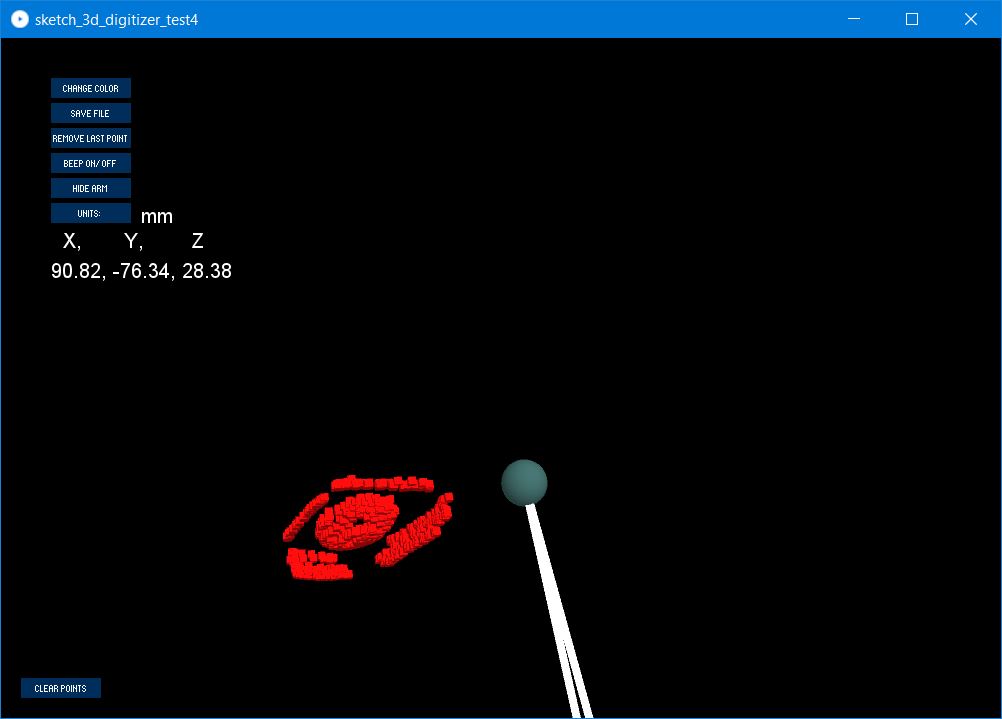
The final result…
Testing
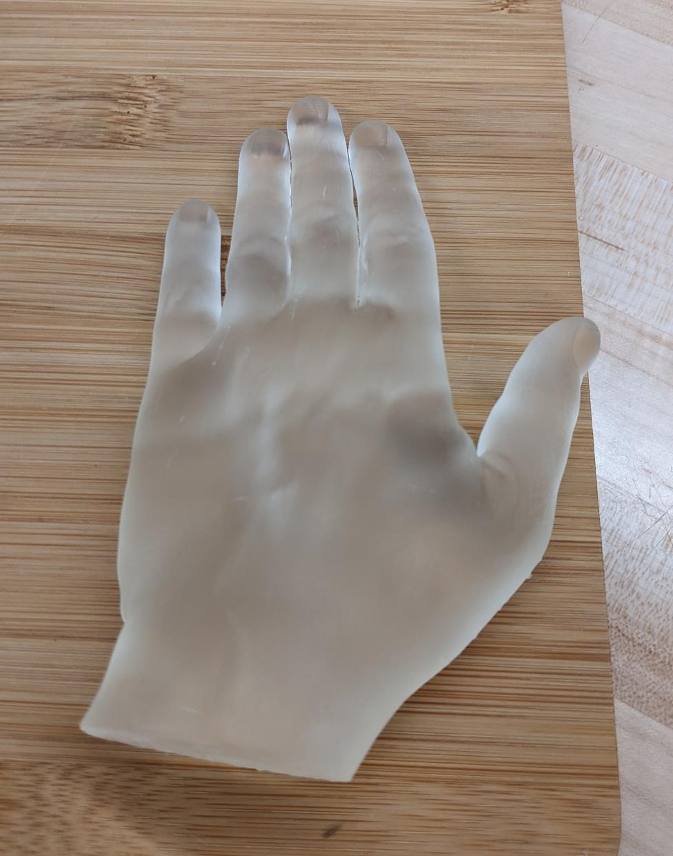
One of the first tests I did on this arm was a 3d scan of a 3d printed hand (about half size of a normal human hand.) The result was not ideal. However, it did take points, and it looked okay at the very least.
First the 3d printed hand:
And the scan…
Well, if you squint just right…
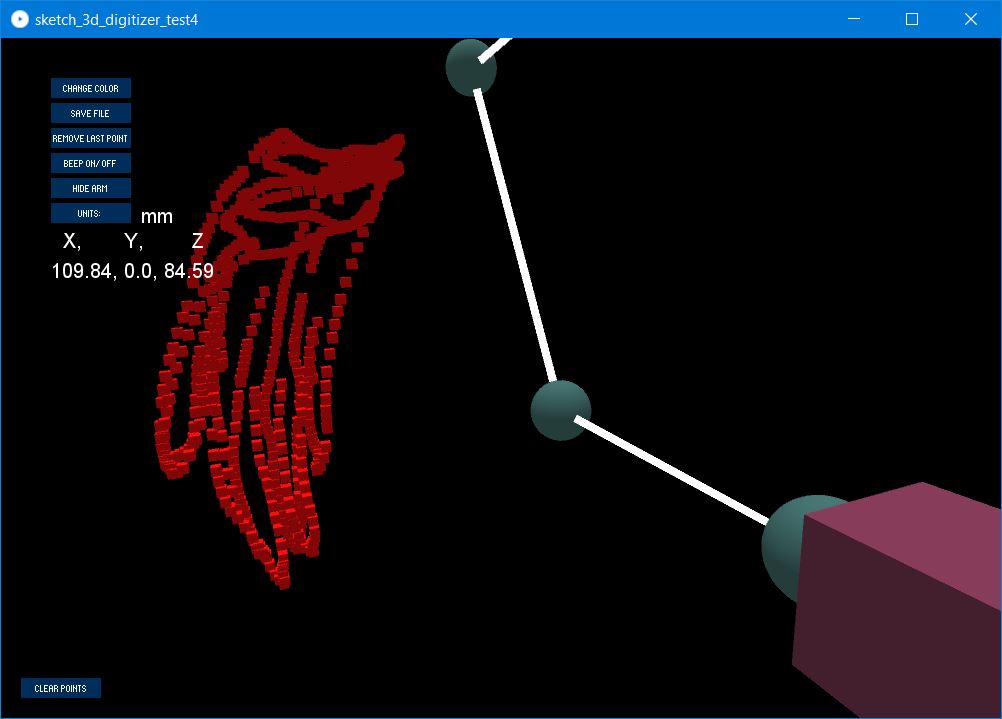
It’s not the best quality, and part of this is that I was displaying boxes rather than spheres (as with my computer, displaying too many spheres with processing really slowed down performance. The boxes did not suffer any of this performance hit.)
Some of the other earlier tests:
Evaluation
I was able to take a known size block and measure it with the arm. However, I wasn’t able to get the results I was looking for, becaue it’s not so much that data is off in terms of a single axis, but rather there is a spherical aberration in the data that makes data analysis difficult (or easy if you really understand trig, which I do not.)
However, it was evaluated, and I deem it a “starting point.”
It’s not great, it’s not bad. It can use improvement, and I plan to improve it.
Calibration
As with any type of metrology equipment, if it’s not tested and calibrated, it’s not much use. I will need to find a way to test the accuracy and precision (repeatability) of this arm when it is finished.
While I’m still to think of proper ways to do this, I believe I can start by testing with gage blocks of known lengths, and ball gages of known sizes, as well as using 1-2-3 blocks and other precision equipment to test with. This will at least give me some indication of basic accuracy. Further tests will be created for examining other aspects of the arm at a later date.
What does it all mean?
I don’t know.
However, this is a good starting point in order to create a higher quality, lower expense 3d metrology and scanning system, as well as a place to start experimenting with different technology and techniques to drive down the price of a scanning arm.
What worked?
A lot of things worked.
I was very happy with the system integration. A lot of parts fit right together right away, and I was able to make a nice small package. The physical part of the design and manufacturing process was fairly smooth.
What didn’t work?
Software, software, software. I knew this was my achille’s heel from the get go, and this was an area that I wanted to get better at. But I just wasn’t aware of how difficult it would be when the due date kept creeping closer. Unfortunately, I wasn’t able to get help due to a number of circumstances outside of our control (sickness, out of town, etc.). This made finishing up the software side of things quite the struggle, and I spent more than half of the entire time on this project focused purely on one relatively small piece of the software.
One of the things I dislike most about this is that I did have other things I wished to try and integrate into my project, but because this software issue was so important and took so much time, I was never able to experiment the way I wished.
I guess there’s always next time I take Fab Academy?
Future Goals
These are things that I’m sure I will not have time to do, but things I would really like to happen (or at least experiment) at a later date.
- Better Software
- Extra degree of freedom at base of probe tip to allow it to rotate.
- Moveable Base – put optical mouse in base, to allow for measurements around a larger part (would necessitate a large surface plate for high accuracy of course.)
- 3d depth camera on arm to allow for more precise measurements using a depth camera and 3d scanning.
- Currently as designed, the arm is not self-supporting. It would be nice to have this feature. Maybe add springs? (think desk lamp)
- higher accuracy, less inexpensive system to capture positions of arms than industrial/commercial rotary encoders.
- Strain Gauge load cell used for the touch probe. This should allow higher accuracy, and simpler design. But requires more complex electronics, and has a number of design challenges of it’s own.
Acknowledgements
My heartfelt thanks to David Taylor, who was an excellent FabAcademy evaluator and instructor. I probably would not have finished if not for his coaching, listening and encouragement. He didn’t need to spend as much time with us as he did, but knowing he was there did a tremendous amout of good.
Thanks to Cori Summers for putting up with my bad jokes and being a good sport of all my teasing and all the incredibly stupid things that I’m constantly saying. I enjoyed the time I spent with you. You still owe me $10 and a steak dinner.
Thanks to Adam Harris, who while dealing with a thousand things, always tried to make time to talk and listen. Though I’m never signing up for anything he tells me to ever again.
And I want to thank my parents and friends who encouraged and supported me throughout this entire process. This class was quite the struggle, and your love and support and confidence kept me going.
And of course, Nova, KFC and Willie Nelson. Because they’re two awesome cats and a dog. (or two dogs and a cat, depending how you look at it.)
Prior Art
I have to say; before doing any research, I started sketching the design based off of what I knew of rotary encoders and digitizing arms/cmm’s/touch probes. You’re not supposed to do that, but I did it anyways. I got excited and I have fun designing things. Afterwards I started to look for prior art and other DIY digitizer arms. Imagine my embarrassment when one of the very first to appear was one from a previous Fab Academy. Oh well.
Digitizing Arms prior designs:
https://fablab.ruc.dk/diy-digitizer/
http://blog.dzl.dk/2018/08/21/3d-digitizer/
- I believe this is just an update on the fab lab project. Which includes a turn table.
- Excellent resource on how he found polar coordinates.
- Github for project: https://github.com/dzlonline/3D_digitizer2
https://www.thingiverse.com/thing:2882172
- I like the way that he added the weight, as well as the large ball bearing around the top of the base. I had previously thought of the bearing, but the weight is a good idea.
https://forum.makerforums.info/t/ccm-digitizing-arm-5-axis-faro-arm/78981
- Github for project: https://github.com/BL-Shopwork/CCM-Arm
Other References and Helpful Links
Found this late, but found it: A fablab digitizing arm project http://fab.cba.mit.edu/classes/863.17/Architecture/people/djmm/0.html
(And his DIY capacitive sensor, which apparently didn’t work: http://fab.cba.mit.edu/classes/863.17/Architecture/people/djmm/10.html)
Ricardo Marques is also building a CMM this year: https://fabacademy.org/2022/labs/fct/students/ricardo-marques/projects/FinalProject/Week10/
“Arm Style” CNC Mill http://fab.cba.mit.edu/classes/863.12/people/will/final/index.html
Digitizer Tutorial http://fab.cba.mit.edu/classes/863.13/tutorials/DigitizerTutorial.html (it uses Rhino for data capture, and has a foot pedal, and seems to use a HID)
Just an overview of scanning https://fab.cba.mit.edu/classes/865.21/topics/scanning/02_mechanical.html
Rotary Encoder References
Arduino Info on Rotary Encoders, contains a lot of information: https://playground.arduino.cc/Main/RotaryEncoders/
Helpful introduction to encoders: https://www.bristolwatch.com/arduino/arduino2.htm
More helpful encoder info: https://brendaabell.com/2014/02/17/arduino-series-working-with-an-optical-encoder/
very helpful, my code comes from here: https://forum.arduino.cc/t/rotary-encoder-using-interrupts/469066/10
Files
The files are listed throughout this page and other pages. Here are some of the main files necessary to complete this project, though this is not an exhaustive list, it should be enough to build this project.
However, you can find the files necessary to rebuild this project here:
Software
Latest version of software for processing (pde file) can be found here
Latest version of software for Arduino IDE (ino file) can be found here
Hardware
And the OpenSCAD code in order to 3d print/cut the parts can be found in the links below:
Electronics
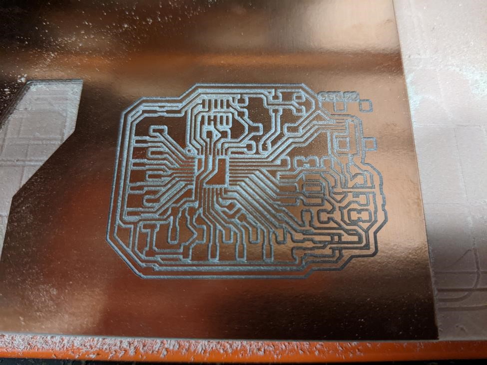
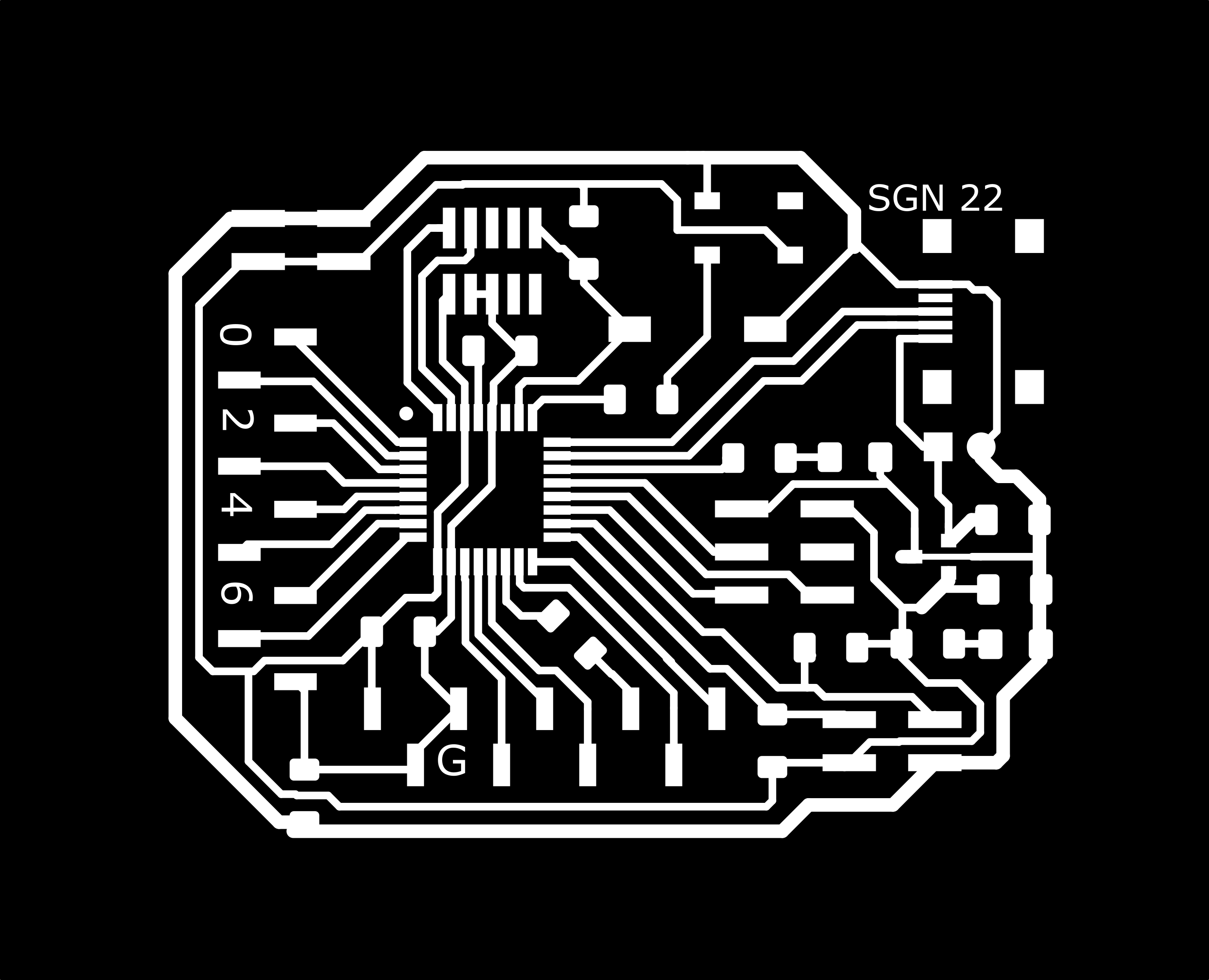
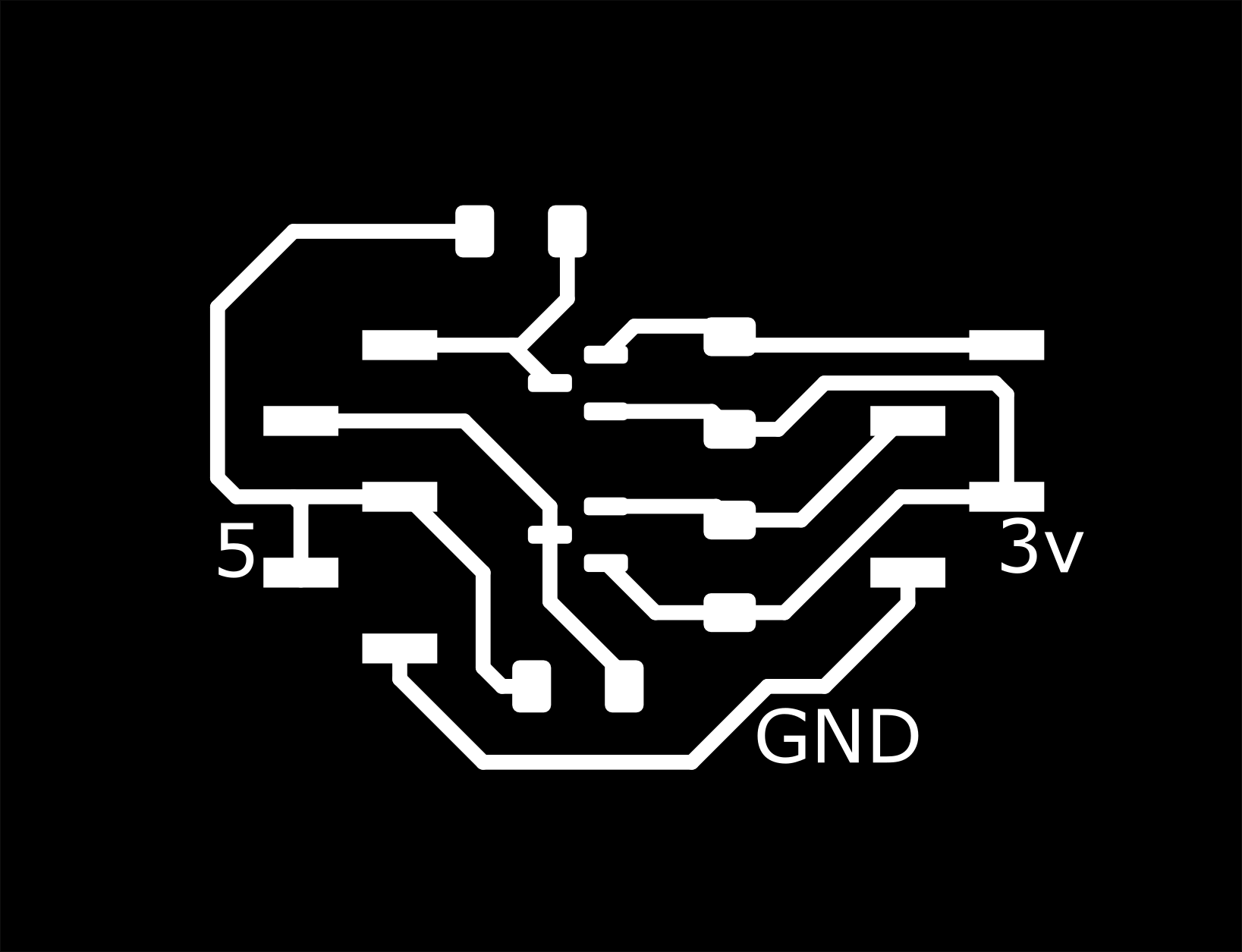
And the PNG files to mill the SAMD21 circuit board and the logic level converter:
SAMD21 SGN Board png Files:

logic level converter board png files:

License
Where applicable: this project is licensed under Creative Commons Attribution-Non-Commercial (CC-BY-NC 4.0)