12a - Machine Building Group Project
April 6, 2022
Build A Machine
For this week, we’ve decided to build a mini-mill for our lab use, as well as a teaching tool discussing all the parts that go into a CNC machine.
This is quite the project to tackle to be built in one week (though it’s likely it will take 2 weeks to complete, largely due to shipping time of getting parts.)
Our Miniature Horizontal Milling Machine
Design
“It’s Substantial” - Neil Gershenfeld
We discussed a number of options to start with. Denny wanted to build a M&M cookine making machine, based off of a 3d printer, which would use the hot plate and an enclosure to bake the cookie.
Cori’s idea was to create a lego sorting machine. This would sort the Lego’s based on size and color using machine vision and a series of mechanisms to sort the pieces in individual bins based on whatever criteria the user selected.
Garrett wanted to create a mini-mill. He wanted something that could be useful to the FabLab in the future (going towards Neil’s philosophy of creating a tools’ to creat tools.) And he also thought this could be a useful teaching tool for mechatronics and machining students.
Garrett made an executive decision, because frankly Garrett does a large amount of the group project work. And if Garrett’s going to spend every waking second of his time building something, it’s going to be something he wants to make. Garrett’s opinionated and stubborn like that.
There were many design challeneges with this. This is the first time we’ve designed a horizontal mill, and the first time Cori and Garrett have designed any type of machine completely from scratch.
And of course, the time limits imposed by FabAcademy is a challenge in of itself. Followed by a lack of parts in our FabLab, and a limited budget (Adam Harris refused to allow me to spend the $20,000 I felt was necessary to complete this project in a worthwhile manner, something about a limited budget…)
That said, we felt up for the challenge.
Not your Father’s mini-mill.
Garrett started on a design for the mini-mill, and there were a large number of changes made right from the beginning.
The design quickly evolved from a typical, vertical gantry style mill like the vast majority of the mini-mill’s out in the world to a horizontal style.
There were a couple of reasons for the design changes.
- Garrett wanted to try to make something different
- A horizontal mill is typically used more often in industry for production work, we wanted to make a model of this for students as a teaching tool.
- We wanted to be able to cut aluminum with this mill, and while a horizontal may not be the best way to design for this, the rest of the design was focused around this goal.
- Garrett thought a horizontal mill would be easier to add features too down the line.
- This design is largely based off of PocketNC’s miniature 5 axis mill. (Hint Hint.)
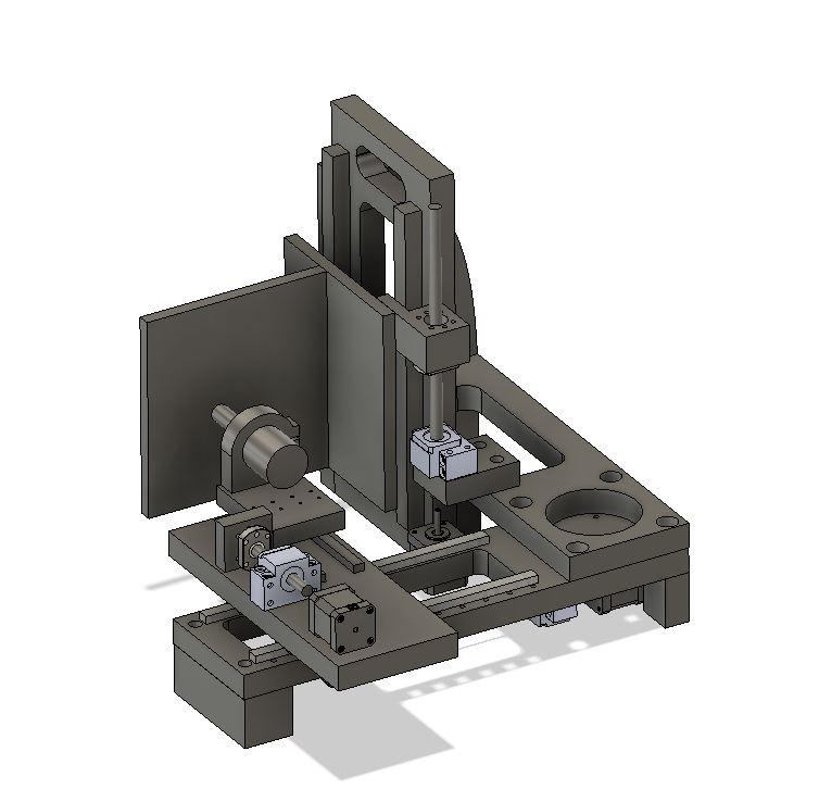
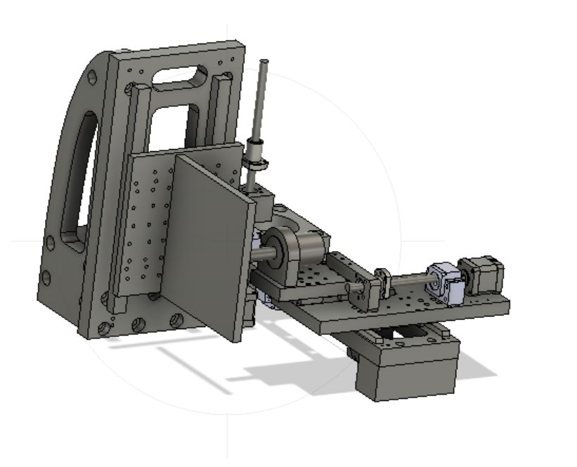
Here’s the first mill design:
Other design decisions included:
-
Using milled Aluminum parts instead of Aluminum Extrusion (Garrett will go to his grave believing that no “mill” should ever be made out of aluminum extrusion) Using aluminum is bad enough as it is.
-
Using Ball screws and linear rails for motion.
- Using stepper motors
- Using a 3d printer board for motion control along with typical g-code.
We’re hoping that this design will be rigid, fairly easy to build (lol), and capable of future upgrades.
Your X, Y, and Z aren’t X, Y and Z.
For whatever historical reason, a Z axis is the axis of the spindle. In this case, that means the Z axis is the axis with the spindle, the X axis is going in a traditional X axis route, but the Y axis is actually the axis that moves vertically. Yeah, it’s confusing.
Software
The design work was done in Fusion 360. One trick we had to use to get around the many issues surrounding Fusion 360 and it’s problems with backward compatibility was to use the CPCC cloud. This way, no matter where, we could use the same version of Fusion 360, and know that we would have access to the files wherever we went. If we didn’t have this ability, we would have been in serious trouble.
We also used Fusion360 for the Computer Aided Manufacturing tools.
We used different slicers for 3d printing. We use the Flashforge slicers for our smaller printers in the FabLab, and the Formlabs slicer for the resin printers. Garrett also used Prusa Slicer at home for some parts.
We also used Inkscape for laser cutting out parts, along with a variety of other software for different parts of the design and manufacture process.
Making a model
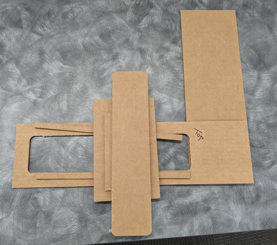
Cori first started out by taking what design work there had been done, and cutting it out the basic dimensions out of cardboard utilizing the laser engraver to get a better idea of size and scale. This was very helpful during the design phase, an area where many people make mistakes. Things appear larger in CAD software than they do in real life.
Work in Progress
We’ve got a large portion of the design work done, however there are still many little pieces that need to be finished:
Large part of Z axis.
- linear rail mount holes, bearing block holes.
- linear rail mount for spindle bearing plate
- finish spindle mounts and their connection to Z plates.
- Final placement of Spindle Height, and spindle mounting
- Final placement of z axis ballscrew, ball screw bearing block, stepper motor.
Other:
- ballscrew nut housings and connections and mounts to axes.
- placement of limit switches and their mounts
One of the problems with a machine like this are all the little details, and making everything fit together, and work together.
And there’s more than just that. The machine needs to designed in a way that make it easy to manufacture, as well as to have a high ability to make tweaks, and allow for the ability to finely control the fit and accuracy of the parts.
While perfect machining and design would normally account for true accuracy, we don’t have those luxuries for this project. Instead, we’re relying on the ability to have adjustability to help tweak and tune the machine. It’s not ideal, but it’s the best we could come up with.
Electronics
While it’d be great to design and use our own control system and motor controllers, we frankly just don’t have time enough to do such a thing.
So we’re using off the shelf controller for the motion control systems. We’re most likely going to be using a GRBL shield for an Arduino. Garrett found an old GRBL shield in his attic, though it was missing the motor drivers. We found some Printrbot Rev B boards at CPCC that should be good, but we won’t know until we test them.
GRBL is a gcode intepreter for DIY style CNC and 3d printer systems. While GRBL is a bit long in the tooth, it’s a tried and true system.
Looking for parts
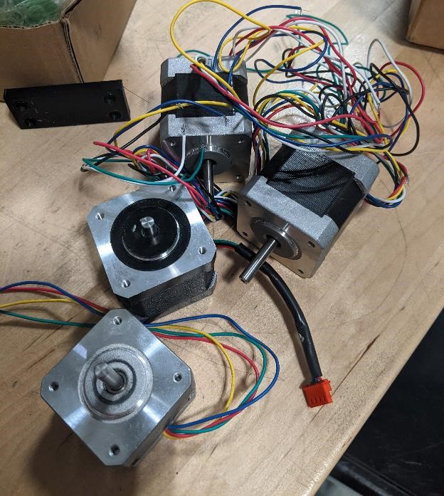
Unfortunately, a large number of our orders for parts necessary to build machines did not come in on time for the start of this project. This means that we had to scavenge what we could.
Adam Harris took us into the storage, and we came away with a number of parts such as stepper motors, a power supply, a couple of old printrbot boards, and other odds and ends.
Garrett had a decent supply of mechanical parts, a few pieces of extruded aluminum, some ball screws and rods.
But between the two, we didn’t have nearly enough.
We priced out a number of parts, and ended up going with the cheapest parts we could get, that could also be delivered in less than a week.
Parts Used
- We went with a couple of different styles of linear rails
- MGN12’s were smaller, used for the Z and Y axis.
- HGR20’s were larger, and used for the X axis travel.
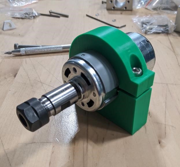
- We used this spindle motor: https://www.amazon.com/Genmitsu-GS-775M-20000RPM-Suppression-Electrical/dp/B08DTHDSMV/
- 1605 and 1204 Ball Screws and Ball Nuts were used, with crappy chinese bearing blocks. (Crappy because they don’t use the angular contact bearings that they should. The ballscrews and ballnuts are amazing considering the price point, even with their issues.)
Building it
Here are some of the many processes we used to produce this machine.
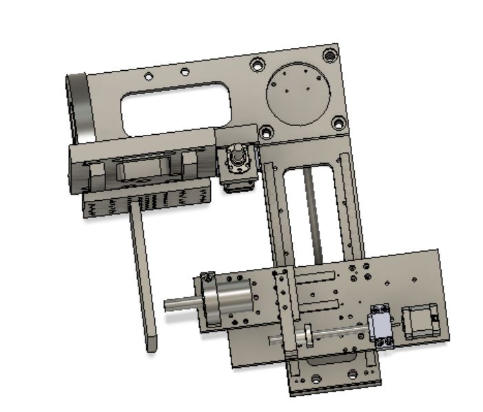
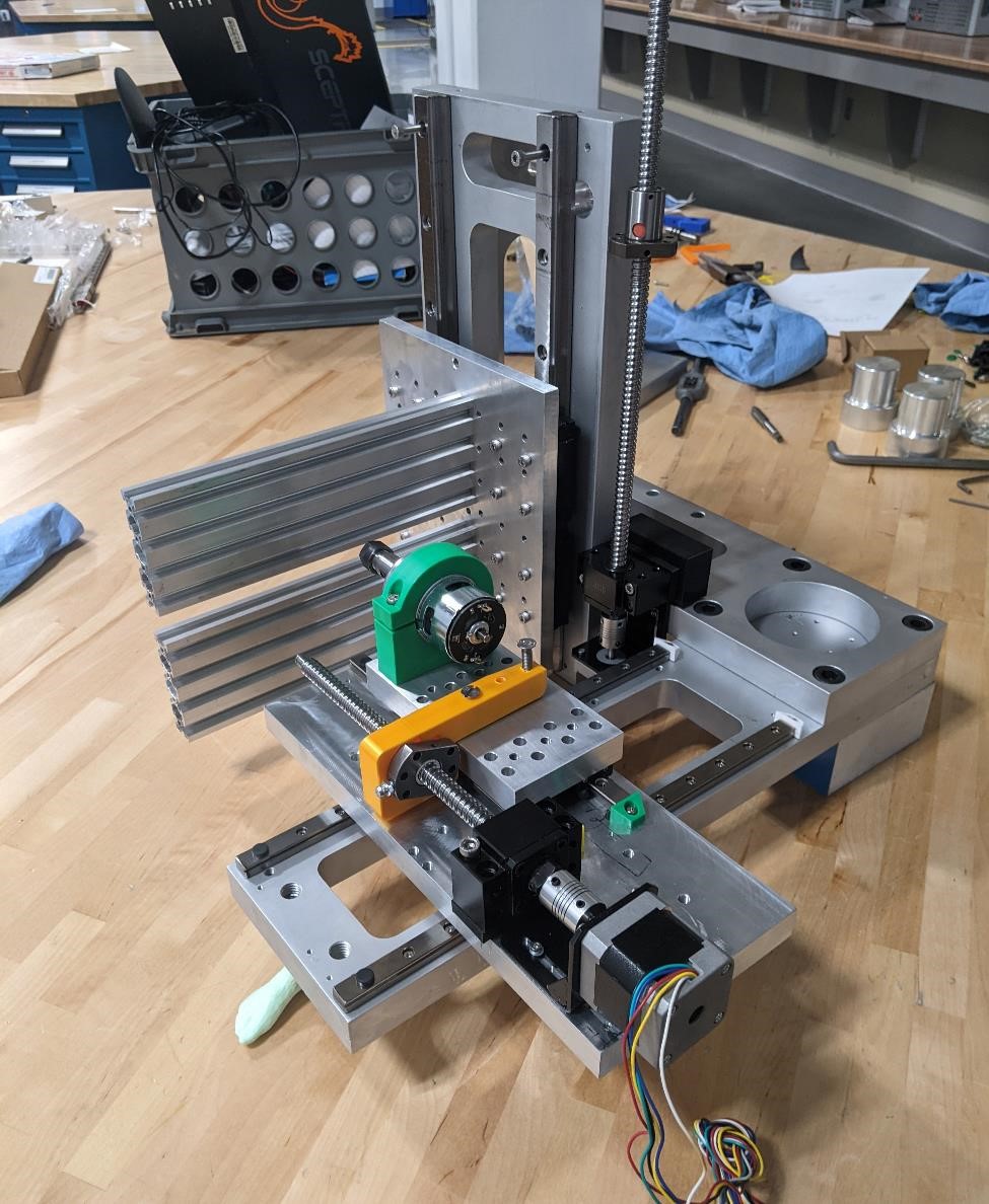
Finalized Design
(Let’s just clarify that this is a finalized design for the purposes of this assignment, not that this machine is at a stopping point in terms of design, function or fit.)
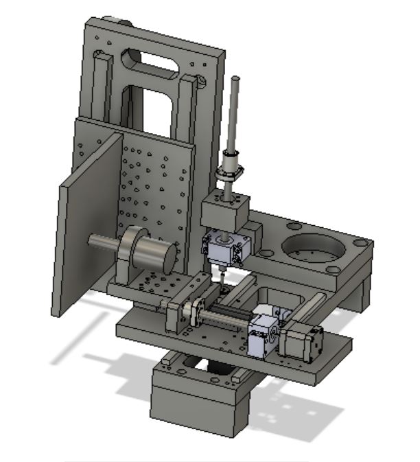
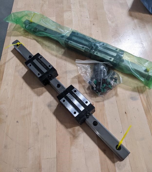
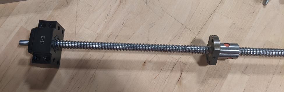
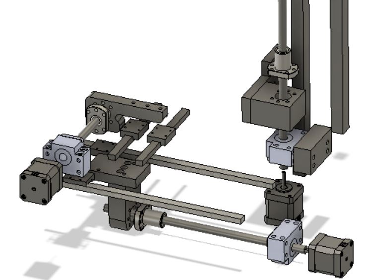
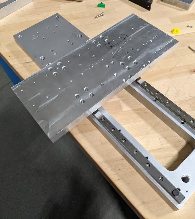
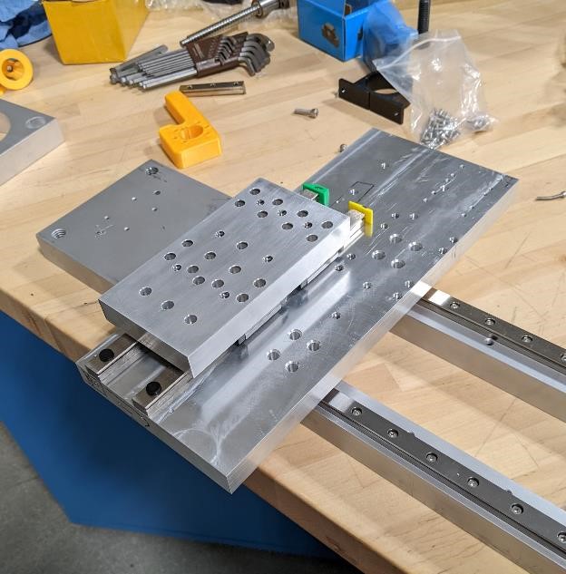
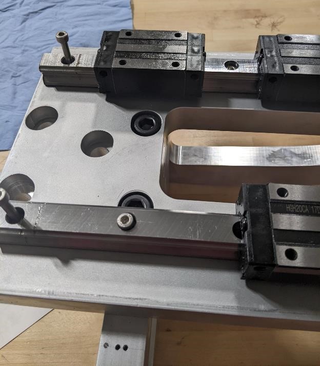
Here’s an image of the ballscrew system and linear rail - the heart of the machine’s motion., with the corresponding connectors to the frame and axes.
CAM
We used Fusion 360 for the CAM portion, to convert our designs into G-code so that they could be run on CNC machines.
We created a number of programs to pocket and drill holes. Mostly the programs were just drilling holes. Lots of holes. To be tapped. Yay.
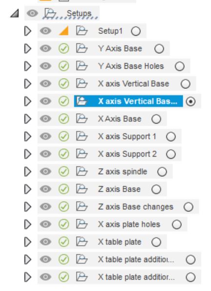
Here you can see a list of the different CAM setups we had created. Some of these are individual parts, some are changes for re-machining as we went through this process.
And here you can see a few of the many toolpaths overlaid on the model of the machine.
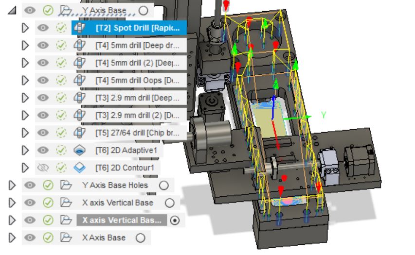
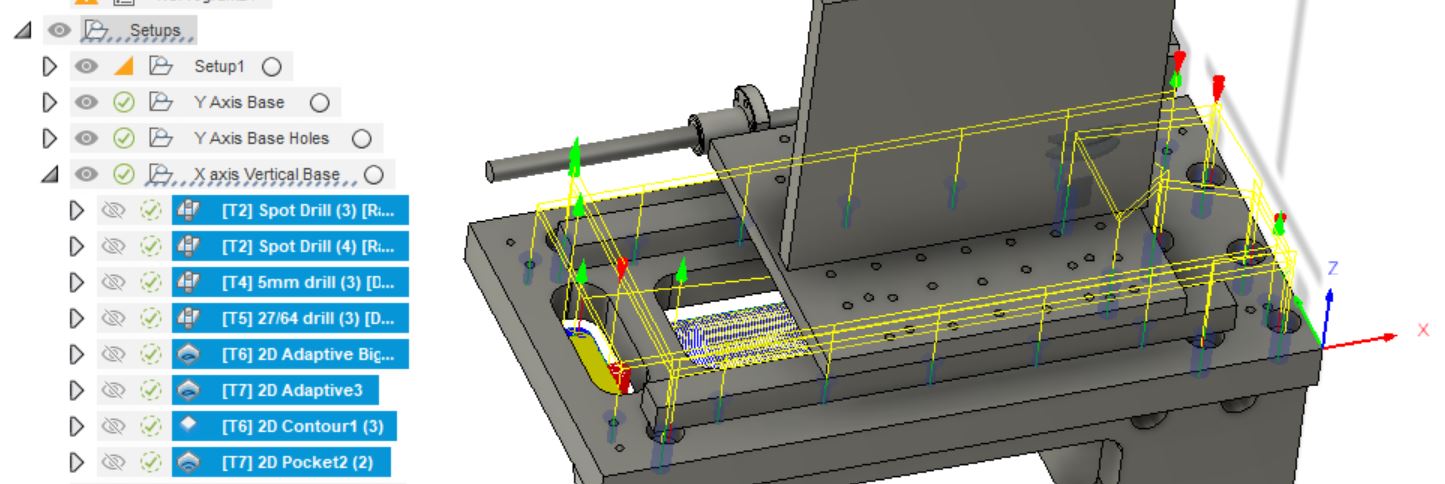
I apologize for not going further into detail about the CAD, but frankly, it really was just mostly drilling a lot of holes. Most of the work was done in CAD, trying to figure out where everything went.
Machining
For more information on using a CNC mill, please refer to our group page for CNC milling
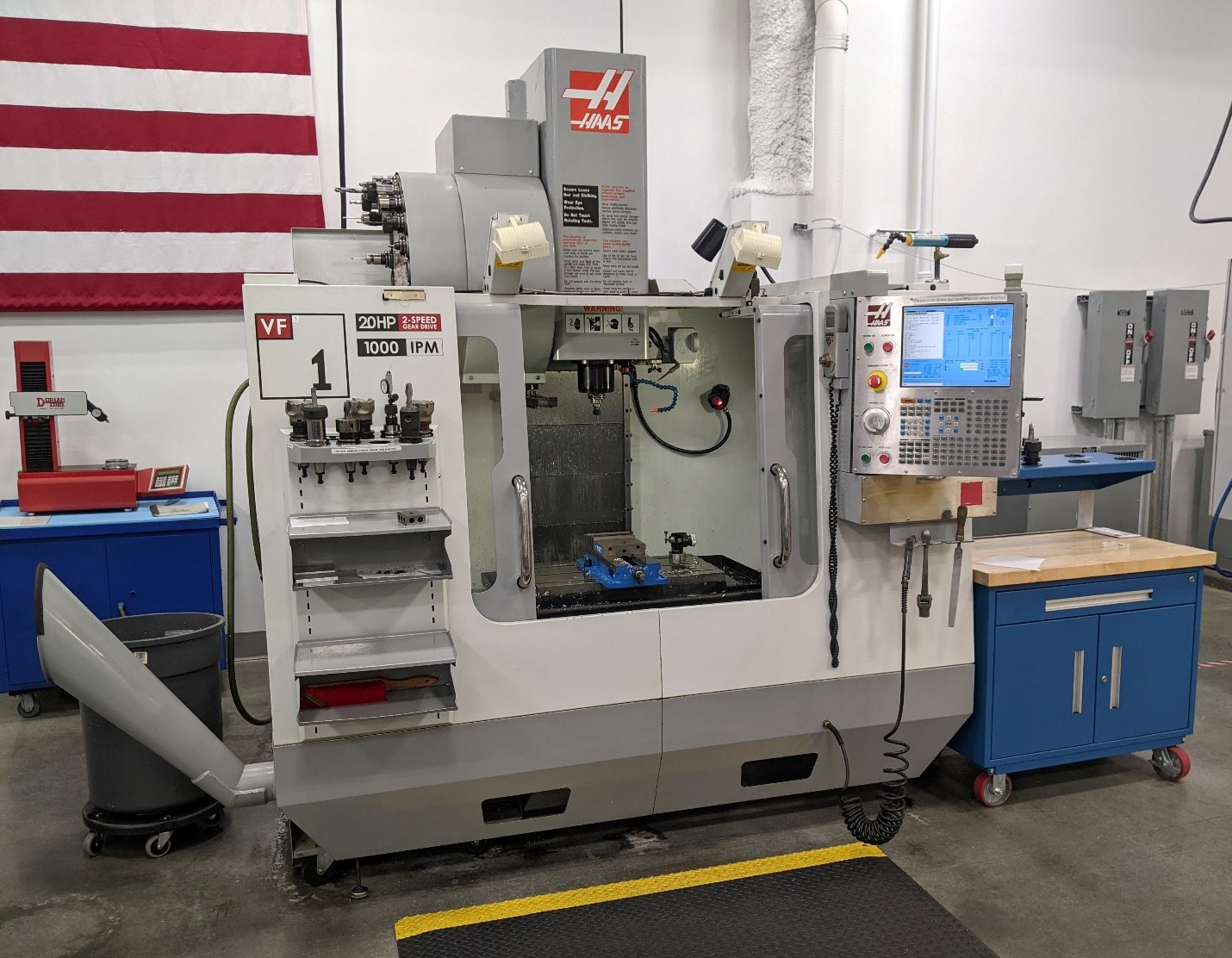
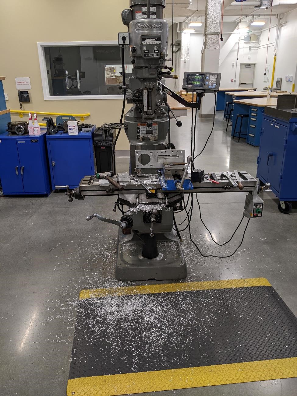
Garrett started machining the parts for the frame of the mill.
He used a Haas CNC VF1 milling center.
Setup and Indicating
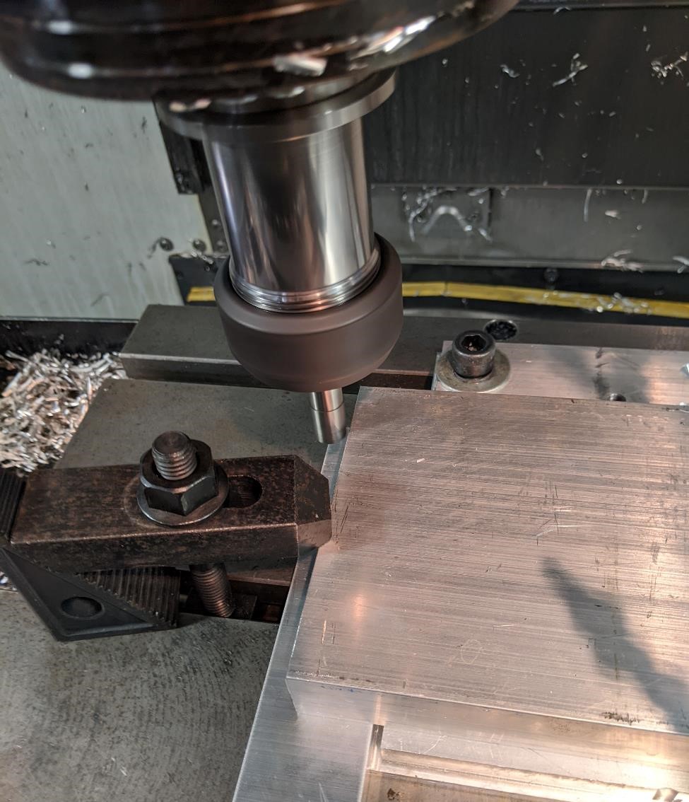
Here’s our Aluminum 6061 stock set up in the machine. I believe this is a 16” x 5” 1” piece, and it will be milled to create one of the parts of the main frame. Note that there are spoil boards (just some aluminum flat stock) under the main piece, so as to not drill into the mill table. This piece of stock was clamped down directly to the table. A dial indicator was used to make sure that the side of the stock was directly in line with the X axis travel of the machine (within 0.001” over 16”, good enough for government work.)
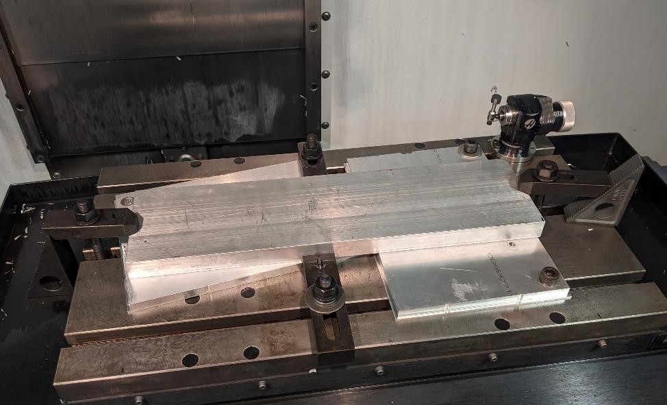
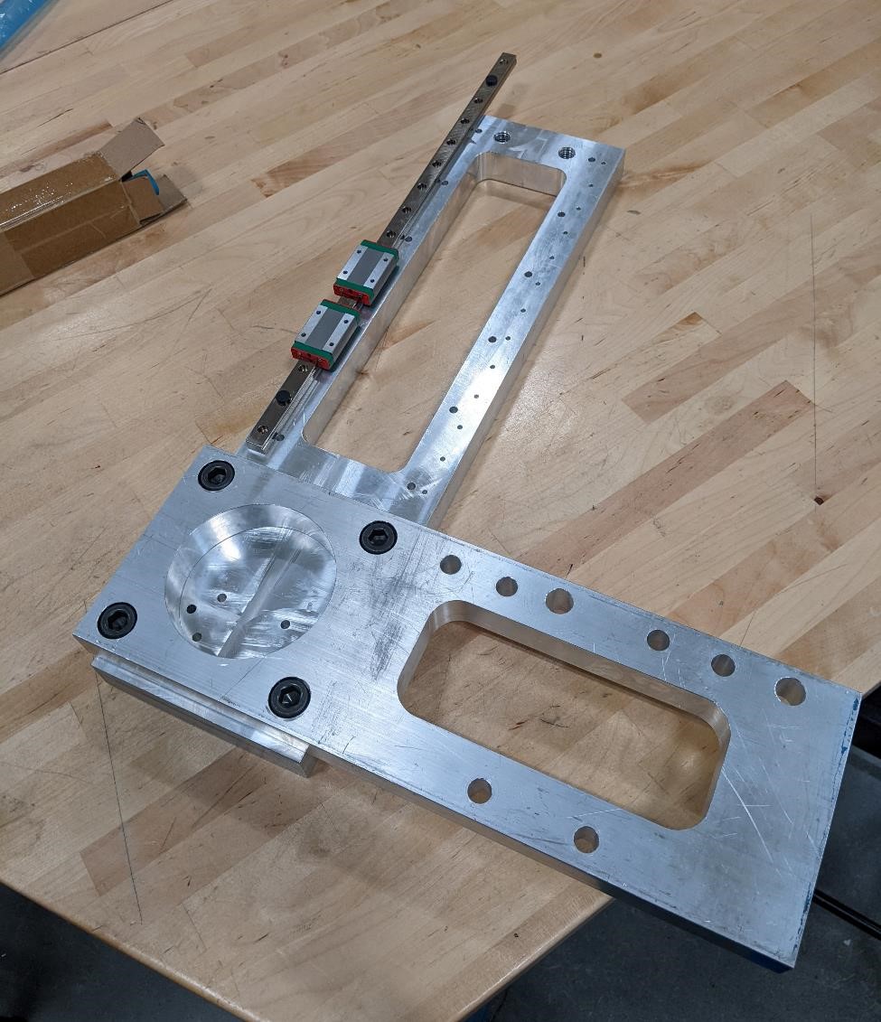
and here’s another part that has been machined in one operation, but is being held for a second operation.
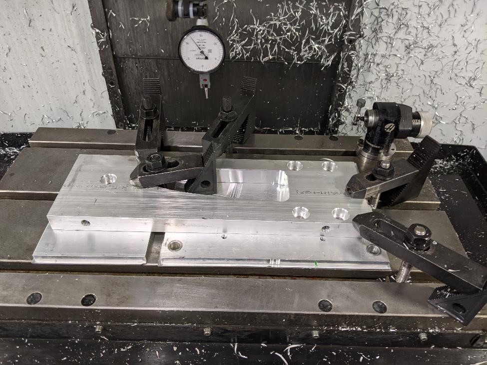
But this part is just sitting on the table. If we were to take an endmill along the front edge, it’d cut a straight line in relation to the machine, not necessarily the part. As such, we need to make the part close to being in the same axis as the X and Y of the machine.
You can use a dial indicator and a hammer to accomplish this task.
When you set the part up, it’s best to have the clamps all finger tight, but to have one point to be your zero position, and to clamp this fairly tight. This will act as a pivot point and help with dialing in the part quicker and more accurately. This takes a bit of practice to get the hang of, but it’s not that bad once you’ve done it a few hundred times.
First, you take a dial indicator, touch it to your part and set the dial to read zero.
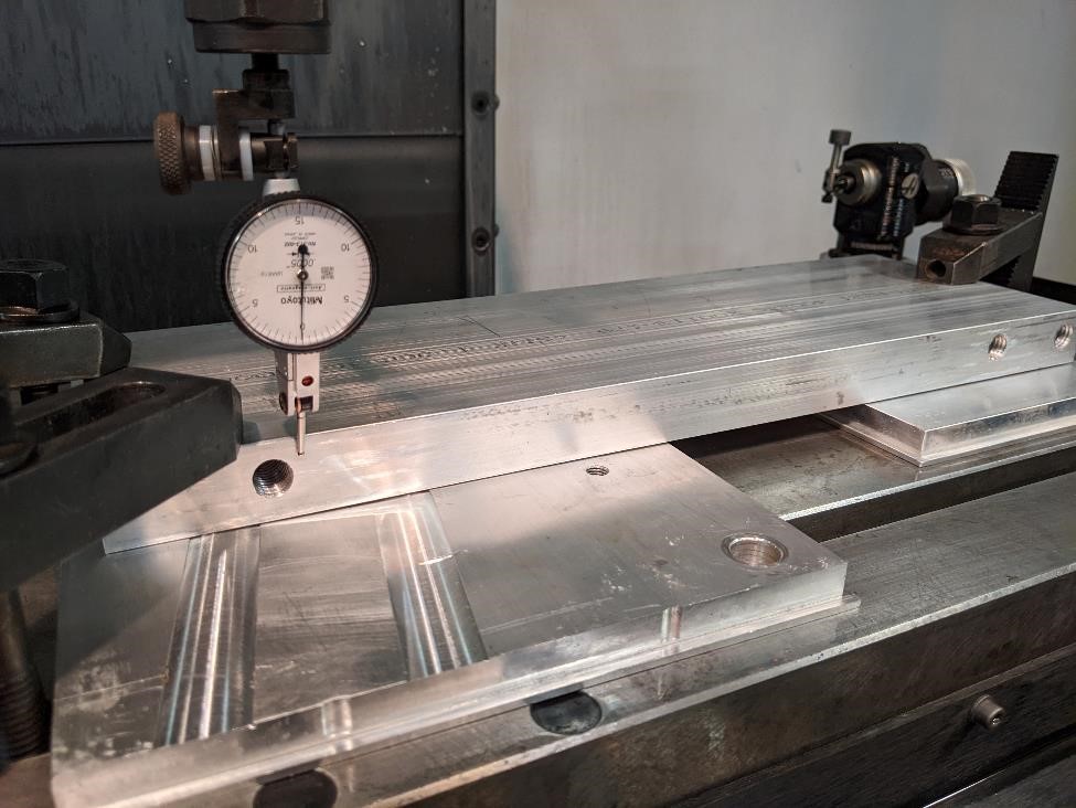
Next, run the dial indicator along the side of the part, noting which direction the dial is turning and by how much. In the below image we see that the dial is 90 degrees from our starting position, indicating it’s about 0.015” off the access.
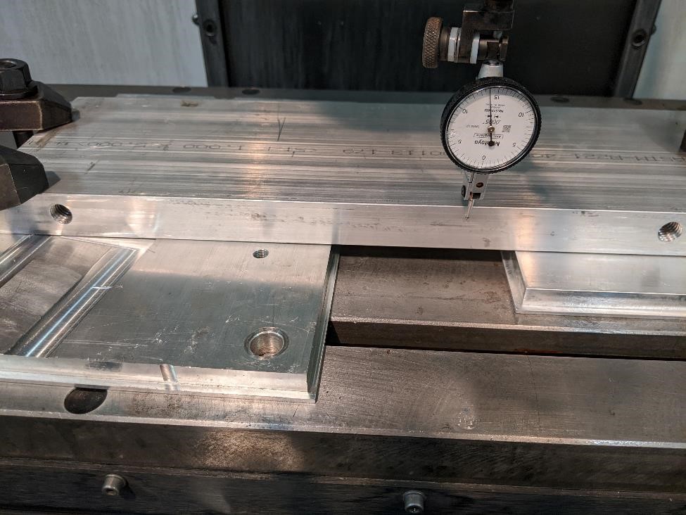
What you want to do, is to use a hammer and gently tap the piece to move the dial in the opposite way it was moving, to align it with the zero point.
The key to this is to go back to your starting point, RE-ZERO your dial, and then continue along to the other side. Gently knocking the part towards zero each time.
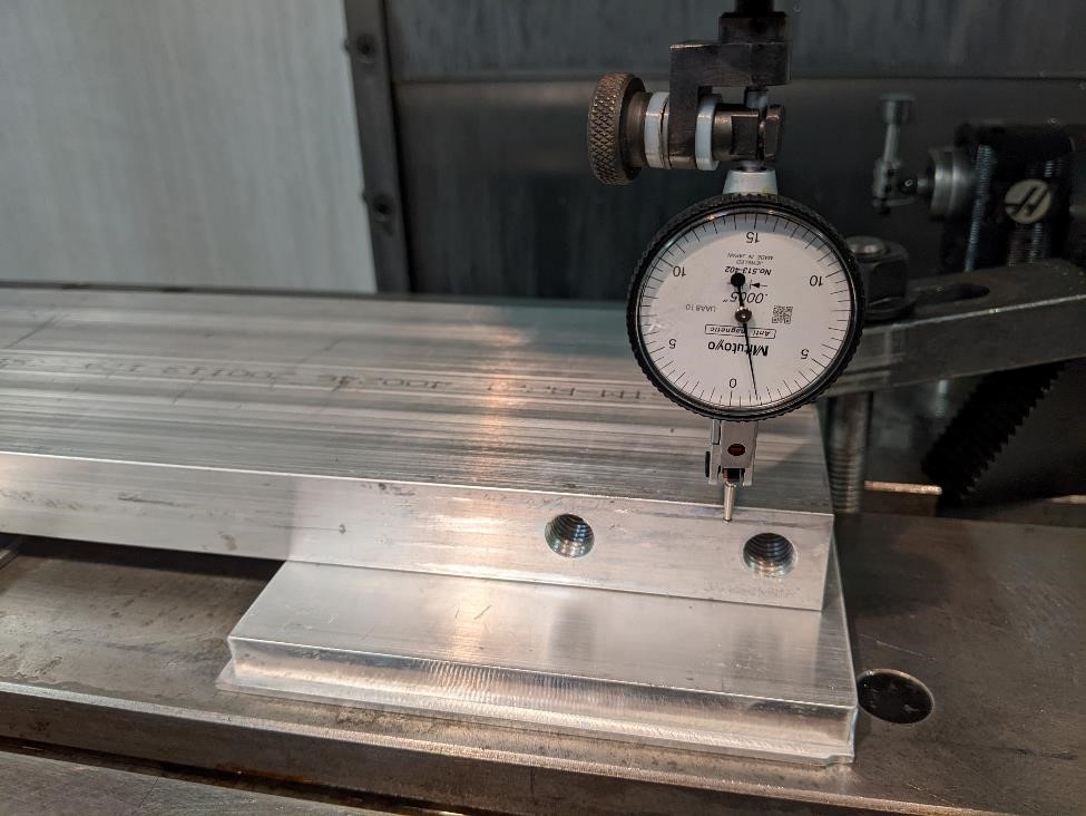
In the above photo you can see we’re out about 0.001” over the 16” of travel. This is just fine for the part we’re going to machine. And this only took about two minutes. Once you get the hang of it, you can accomplish this task quite quickly.
And now, tighten all the clamps and you’re ready to machine a part that will hopefully be accurate!
Next we’ve got to set the machine up, and find the edge of the part in order to tell the machine the Work Coordinate System (G54), ie the location of the part in relation to the machine. We can use an edge finder to do this.
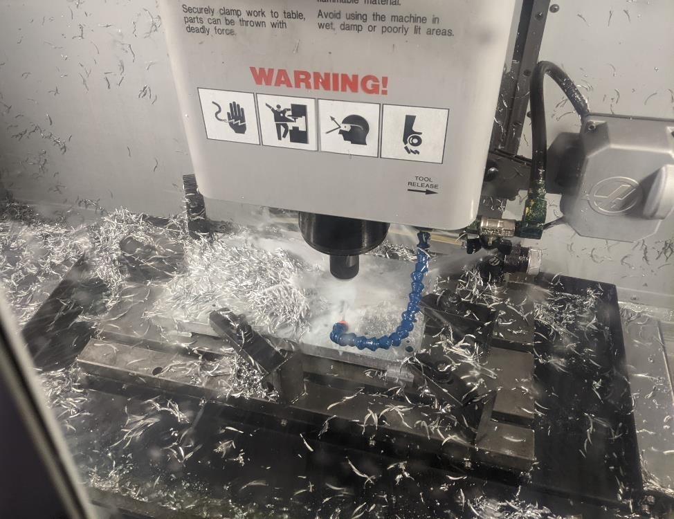
Milling
Next, we’re going to start cutting and make a mess.
We used just a few different tools on this part.
Tools Used For these parts
- 3” face mill
- 1/2” Spot Drill
- 2.9 mm drill (more on this later.)
- 5 mm drill
- 3/4” 2 flute, High Speed Steel End Mill
- 1/2” 3 flute HSS End Mill
The speeds and feeds for the endmills were very very conservative. part of the reason for this was the fixturing of the parts. They weren’t clamped down as tight as Garrett would have liked, and to compensate, we just run the milling tools slower (the drilling doesn’t matter so much.)
Speeds and feeds were around 60 ipm and 5000 RPM for the 3/4” endmill.
Now we just need a brave man to push the button for us....
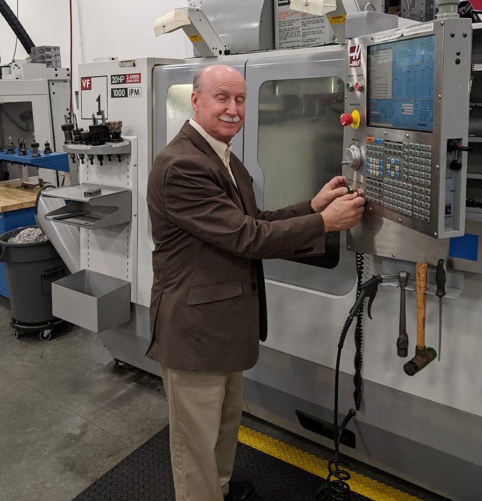
And …
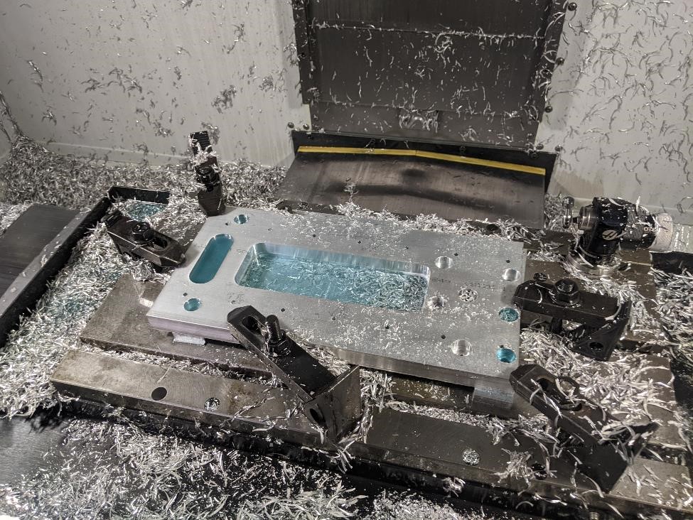
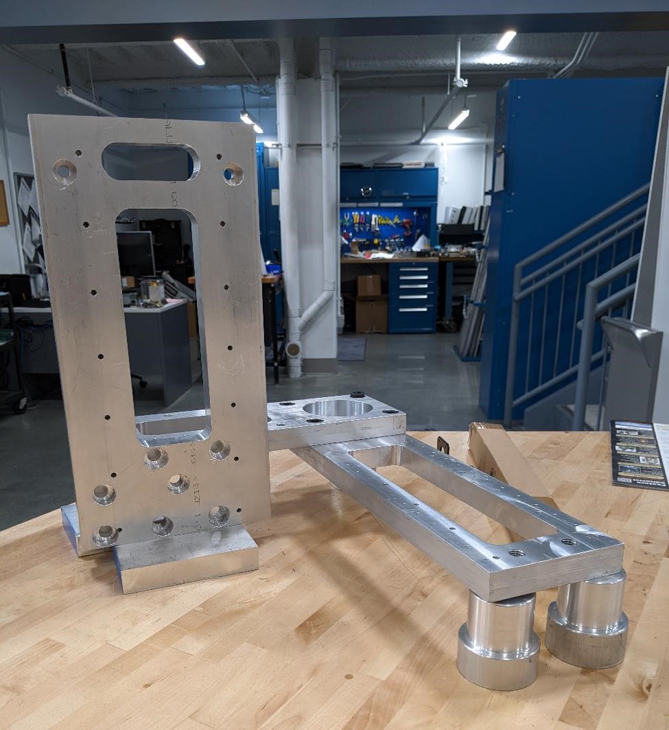
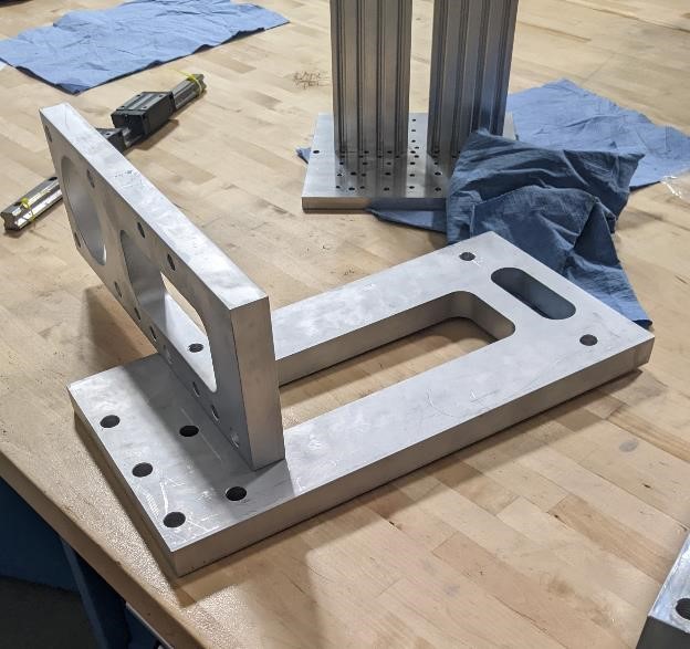
And here’s one of the finished parts in the machine, ready to be pulled out.
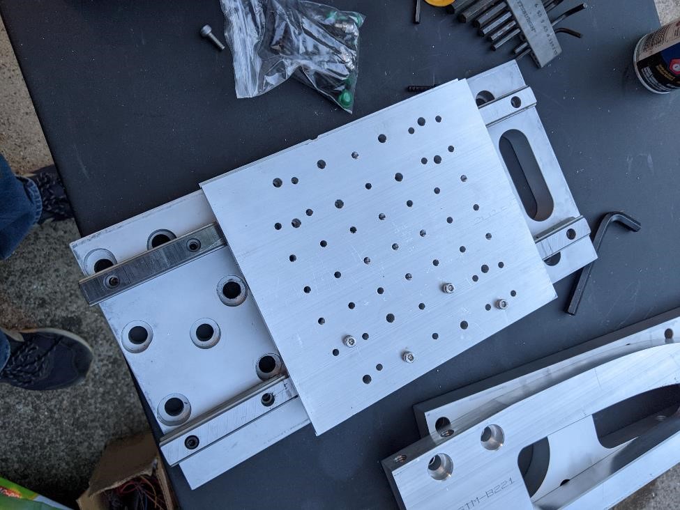
And here’s the first two parts milled and bolted together for a test fit.
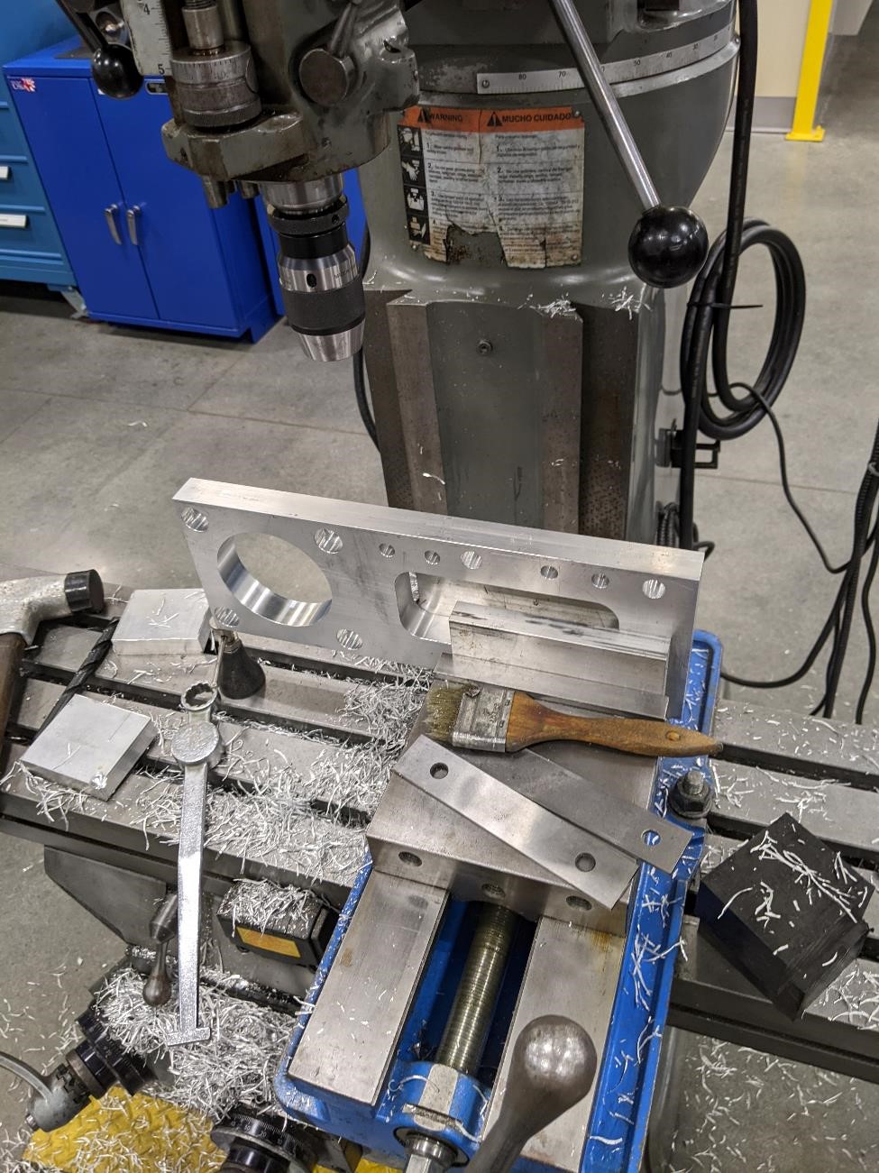
However, we’ve got a make a couple of extra holes and tap them. For parts like this, it’s usually much easier to just do this on a manual mill than bothering to set up and programming a CNC, since this is a second operation. It’s quicker to do it on a manual mill if you have experience on one.
Though as you can see above, it is a much messier process.
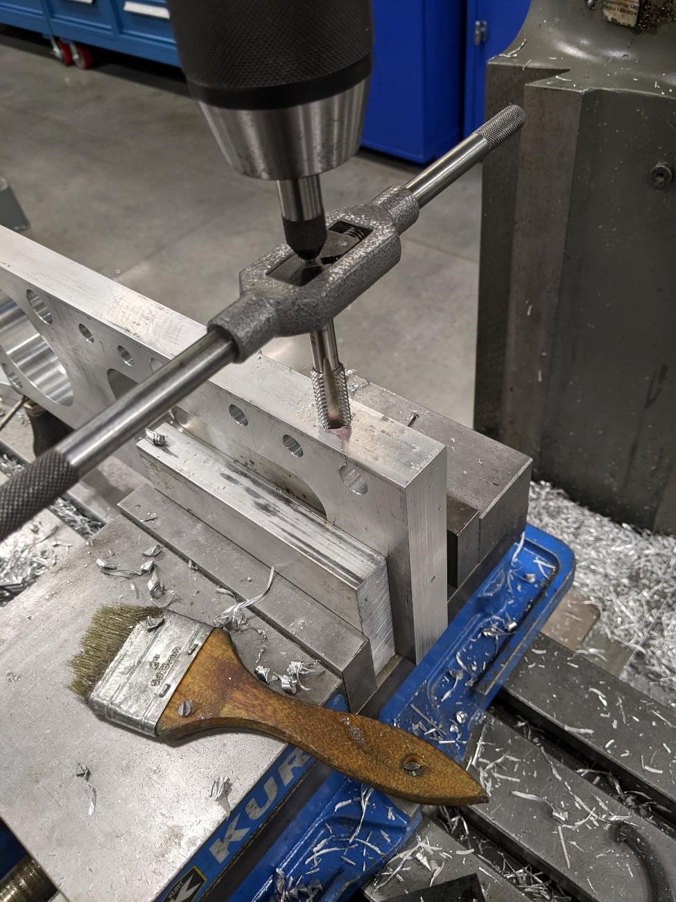
Below you can see the stock set up on it’s side for drilling and tapping. Note that it’s being held in a vise, but one end is being supported by a machinist jack to help keep it stable and level.
And here’s the tapping method being used. The tap is being supported by a tapping guide in adrill chuck (it has a spring loaded tip that “follows” the tap up and down to help keep the tap centered and from going in at an angle.)
And three parts being prepared for bolting. Only 15 more parts to go!
And some more parts, milled a night later.
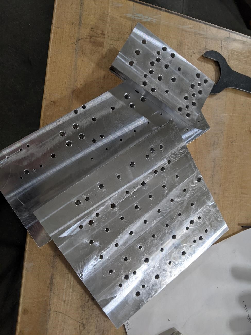
There are three broken 2.5mm drill bits in one of those parts. Garrett hates small drills.
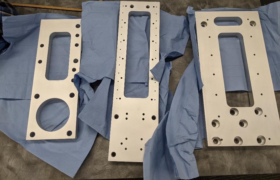
Garrett was unable to do work at the college one day, and took the parts home with him and hand tapped a ridiculous number of holes. He used a 3d printed tapping guide he found on Thingiverse that made things much easier. Also found that Liquid Wrench acts as a decent tapping fluid, but it evaporates fairly quickly.
Cori took these parts with her, and sandblasted them. They came out beautifully.
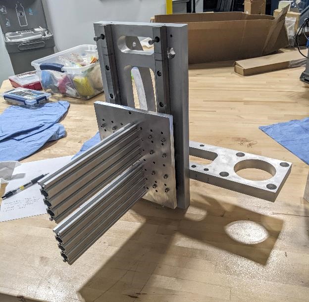
Some Assembly Required
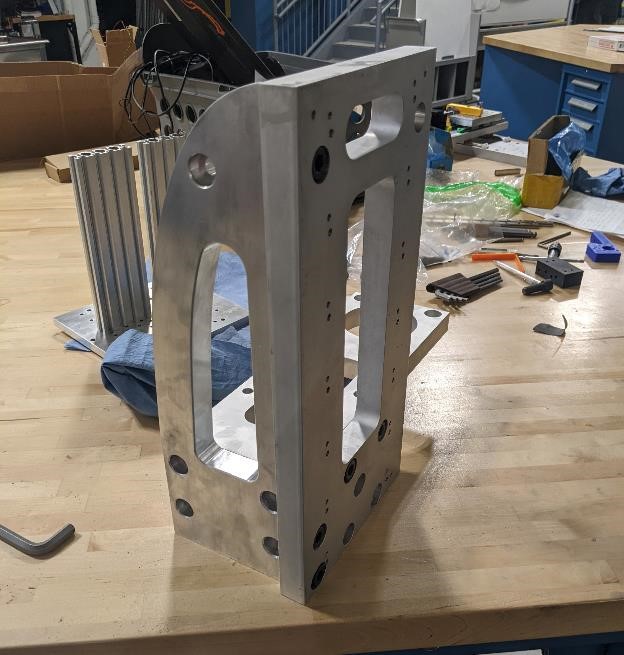
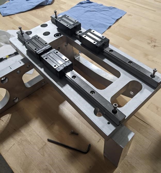
And then we started a pre-assembly to see how the parts fit. They fit well enough.
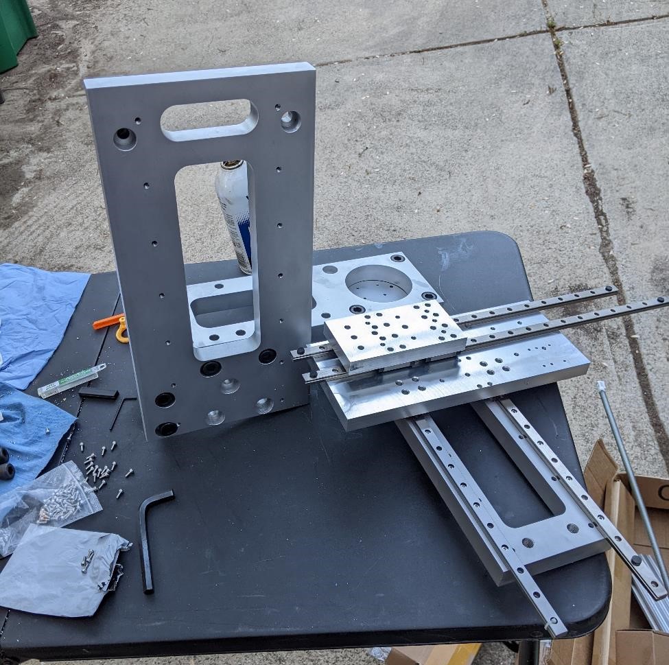
Garrett spent forever hand-tapping holes, but it was worth it when the rails went on, straight, and there was no binding of the linear rails what-so-ever.
Here’s more information than you’ll ever want to know about linear rails and installing them: https://rockfordballscrew.com/linear-guide-rails/assemblies/
Having this move around was a very satisfying experience for Garrett.
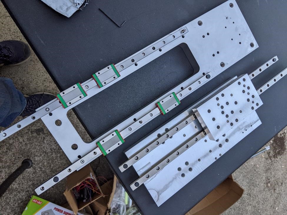
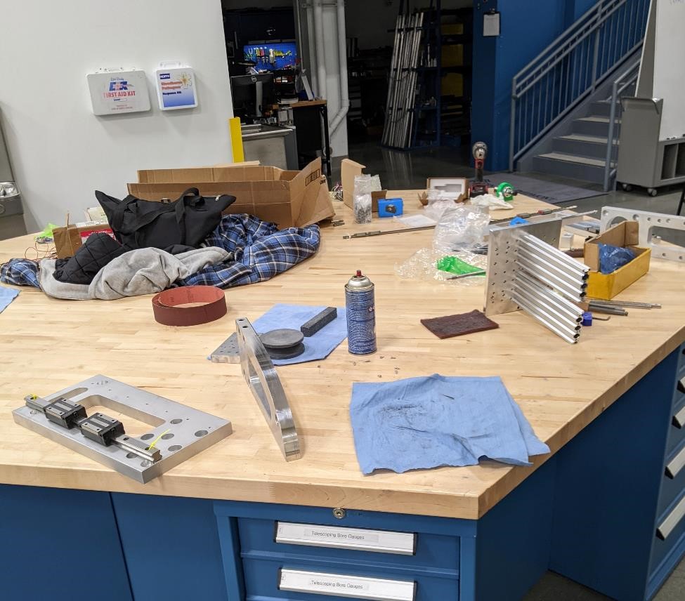
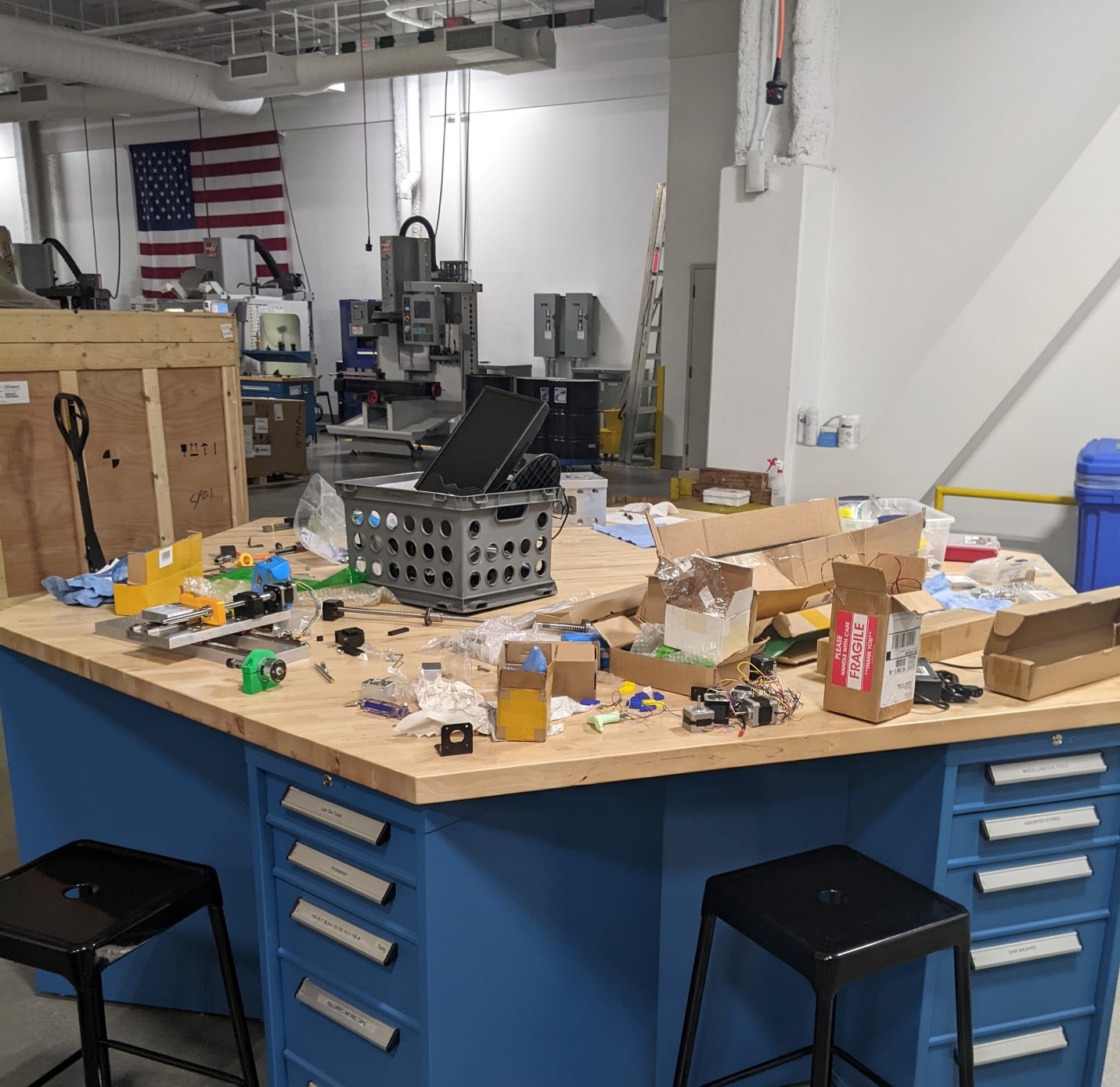
And here are most of the parts and everything else creating a mess in the shop being prepared for assembly
Ross was kind enough to chop the rails for us, and now they actually fit on the part.
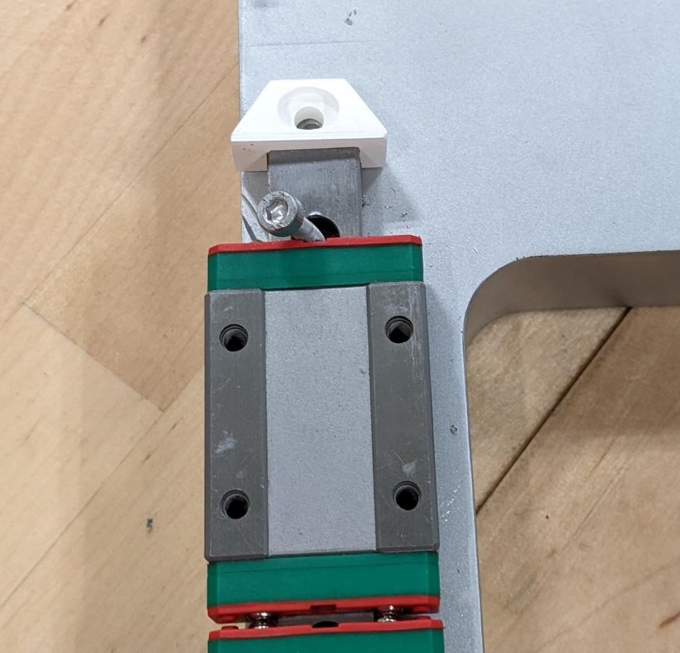
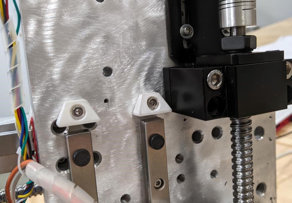
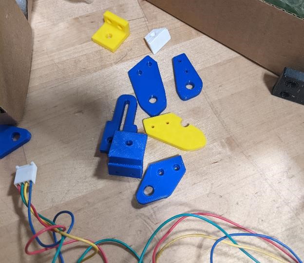
And we 3d printed a couple of small parts, such as these end stops for the linear rails (hopefully they keep the rail carriages from flying off the rail). They were 3d printed on a Formlabs 3L printer, out of Rigid 10K resin. They were prepared like most prints, washed, and cured for 1 hour at 70C temperature in the UV lightbox/oven. This was also supposed to print the spindle housing, but this print failed. WhisperingIbex promised they would do better next time.
These parts are quite rigid, but rigidity is not the same as toughness. It’ll be interesting to see how they hold up over time. But if endstop switches and soft limits work well, they’ll never be used (hopefully!). They also have a very “plaster of paris” like feel. Cori did some research and found that if you rubbed mineral oil on to them, they’d have a more plastic like finish. We’ve yet had a chance to try this.
And here’s some of the limit switch holders we printed out on a typical FDM style printer.
And this is after a very long day, a complete mess, but work is being done.
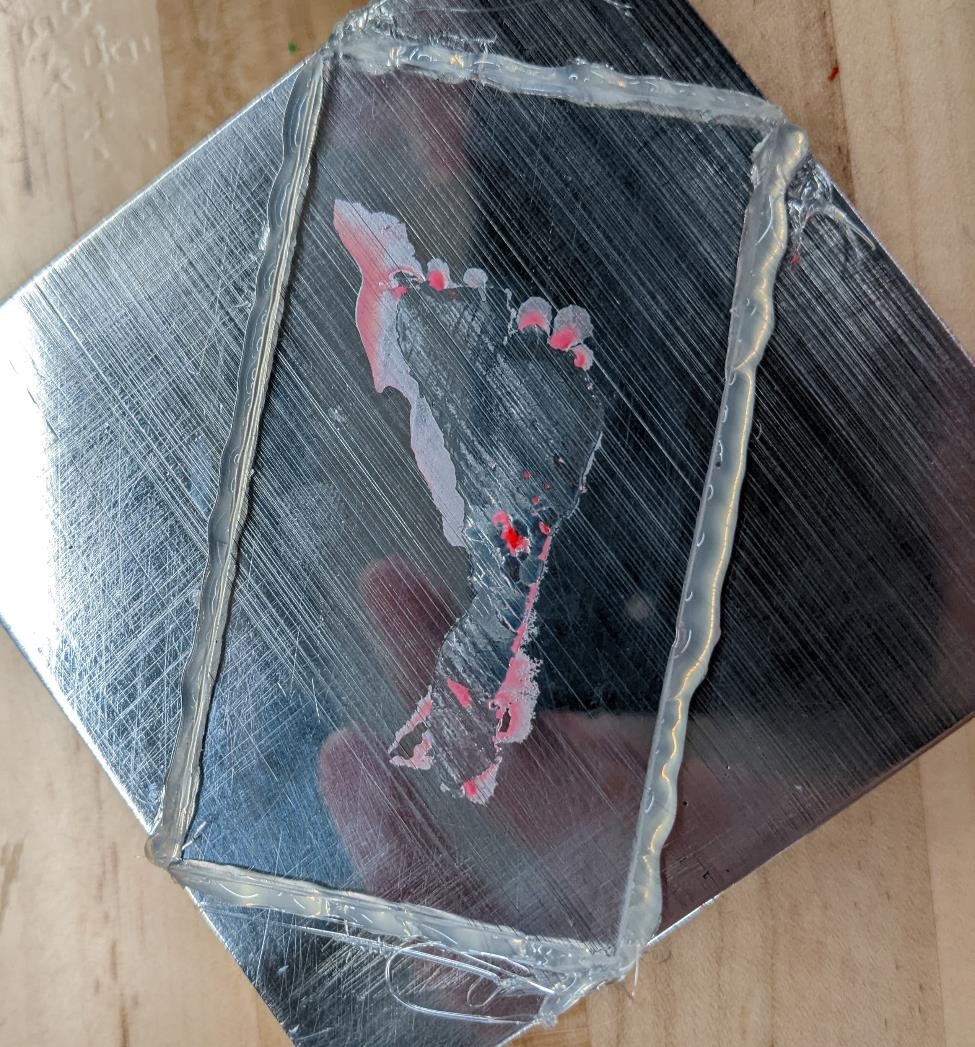
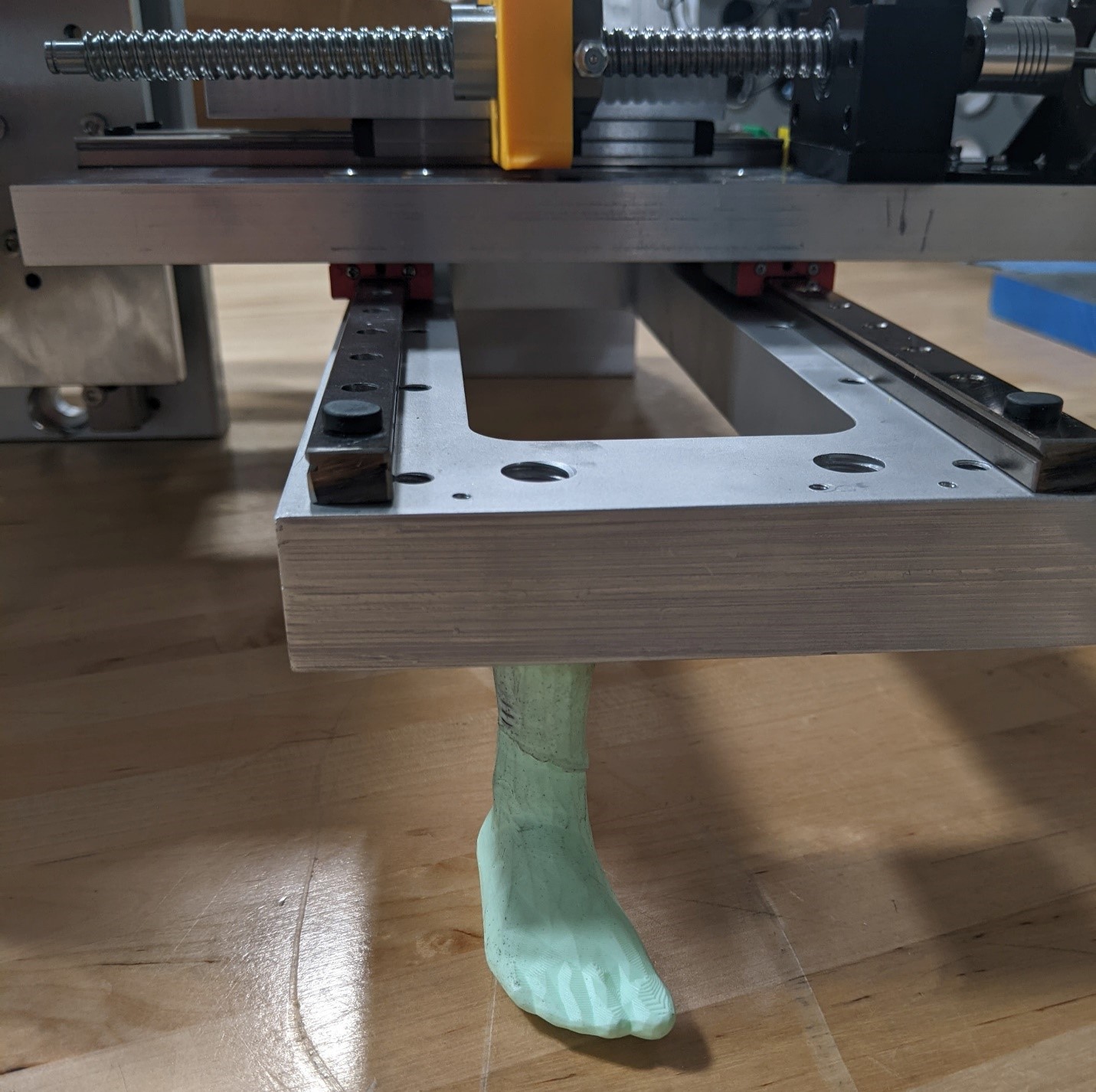
And a very cool Zombie Foot
Setting up Electronics
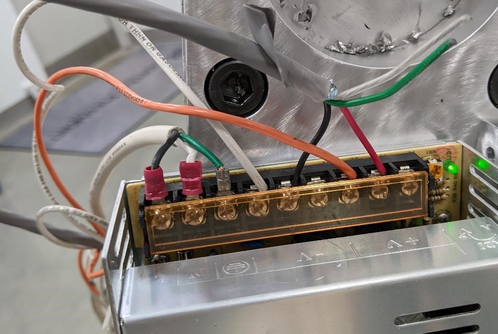
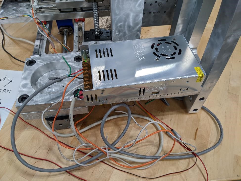
The first thing we had to setup was the power supply. We’re using a 12v power supply that puts out about 10 amps.
Denny Leak helped us with this part of the project and wired up the power supply.
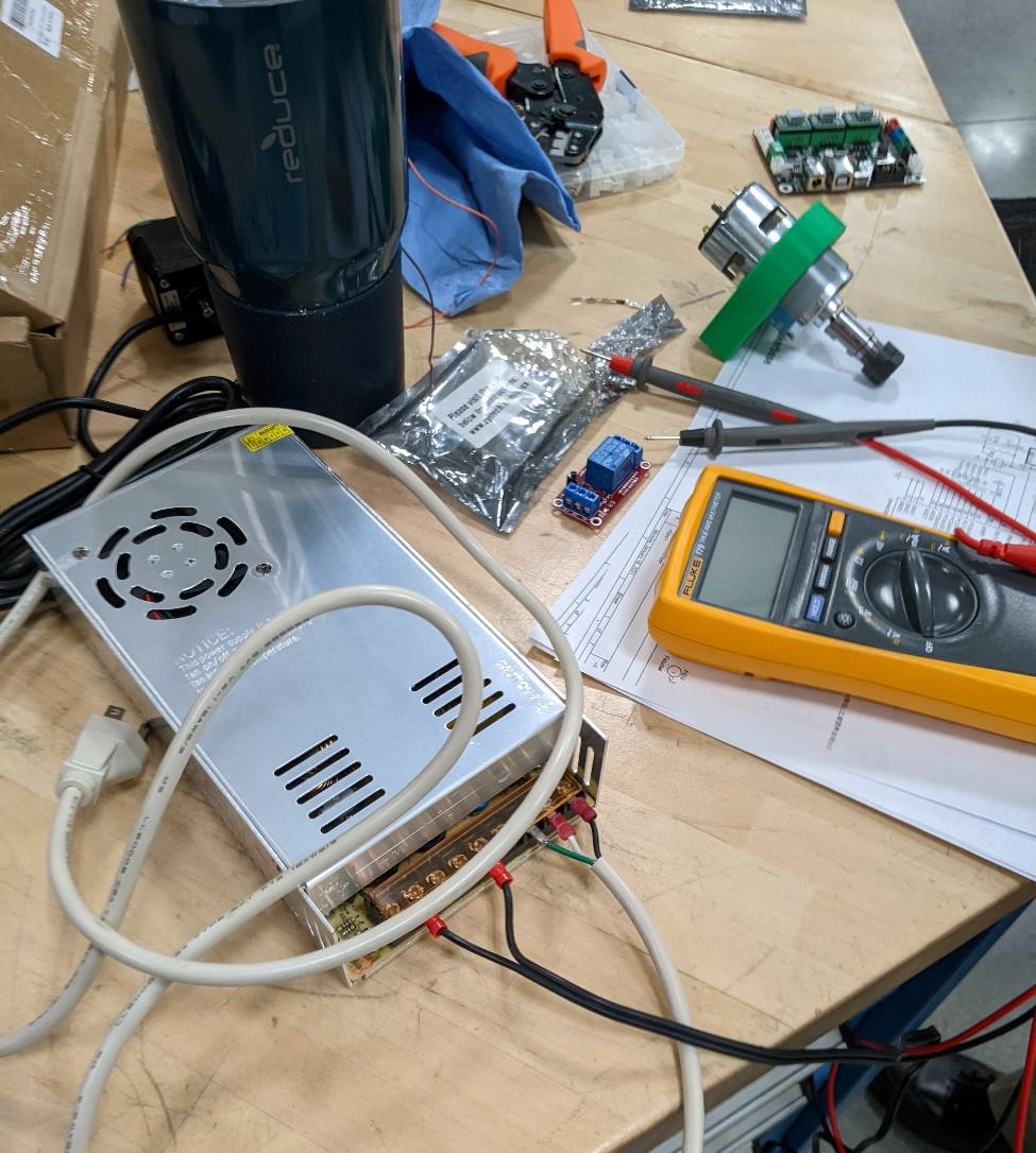
You connect the power supply to a wall power cable (120v AC), making sure that you have proper connections, and then we connected the 12v DC output to the GRBL shield, which will provide power to the motor drivers and stepper motors.
Installing GRBL
As noted in other places, we’re using a GRBL capable Zyltech Arduino CNC controller shield with an arduino. (You can find instructions on setting this board up here: https://www.zyltech.com/arduino-cnc-shield-instructions/)
Monday and Tuesday saw the machine getting close to finished. Yet we weren’t there quite yet. We had some issues with the electronics, but fortunately, Denny helped and helped with these aspect of the project.
We started putting together the control boards. This was a bit harder than expected, mostly due to a mixmash of old parts of unknown provenance and functionality. Denny was able to finally able to crimp cables for us for the cut stepper motors, but this was just the start of issues.
The MKS board we expected to use seemed to have a number of issues and we couldn’t load up a GRBL hex file.
We were able to upload the GRBL hex file to the arduino no problem. We’re fairly certain the MKS board was broken.
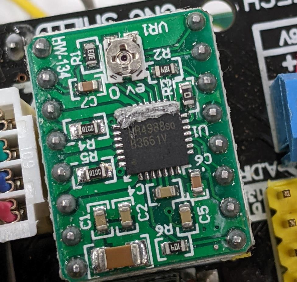
We switched to a RAMPS-like board running GRBL. This board acted as an Arduino Shield, and we were running A9488 motor driver chips for our NEMA 17 Stepper motors.
In order to upload the GRBL code, we downloaded the hex file from: https://github.com/gnea/grbl/releases
We used GRBL version: grbl_v1.1h.20190825.hex
I uploaded the file using a Raspberry Pi with a USB cable connected to the Arduino.
One of the first things I did was to make sure that these boards were seen by the Raspberry Pi.
You can run this command:
dmesg
and it will give you information about what’s happening with your machine. Pay attention to the last few lines, as this will show you what has most recently occurred. I was looking for any type of USB connection.
Windows has “COM” ports. Linux has “/dev/tty*”. In this case, I found something had occurred with “/dev/ttyUSB0” and I knew that the Arduino board had connected to the port USB0.
I used avrdude to flash. This was already installed, but if it isn’t, you can:
sudo apt-get install avrdude
And then I changed to the folder where I had the hex file saved, and ran this command to upload the GRBL hex file to the arduino:
avrdude -v -p atmega328p -c arduino -P /dev/ttyUSB0 -b 57600 -D -U flash:w:grbl_v1.1h.20190825.hex:i
This didn’t work the first time for me. I changed the baud rate from 57600 to 115200 and this worked perfectly.
avrdude -v -p atmega328p -c arduino -P /dev/ttyUSB0 -b 115200 -D -U flash:w:grbl_v1.1h.20190825.hex:i
Setting up the GRBL Shield to Arduino
Here is the GRBL compatible shield connected to the arduino and wired up to the stepper motors and power.
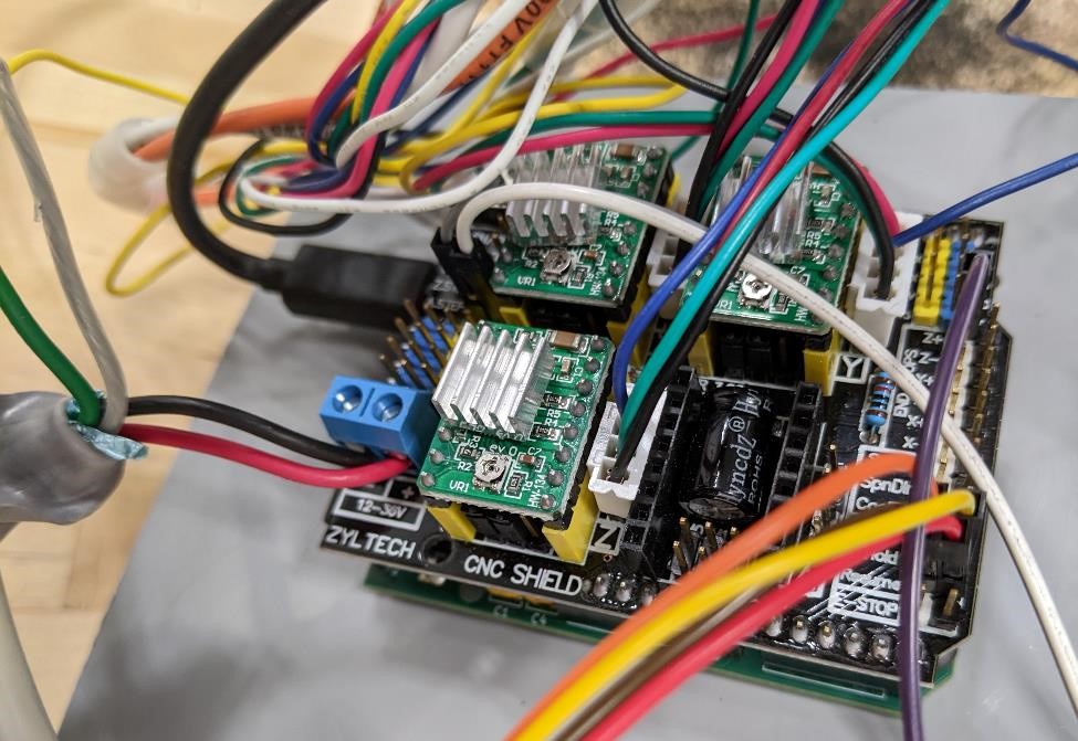
With a students help (thanks Zach), and other helpers, we were able to set up the steps per mm and make sure that the drivers for 1/8th stepping. (We had to change the jumpers on the shield in order to do this. You need to make sure that the motor drivers you are using match the right stepping settings that you’ll be using. refer to the information about your motor drivers and the shield/board you’ll be using.)
We also used the Prusa Calculator to set our steps per mm. This was based off of the ballscrews, which have a pitch of 4 mm. With this information, we set our steps per MM to “400.”.
GRBL Config File
GRBL is just the firmware/software to control the machine. It has to be properly configured for each different machine. Here is some of the the basic settings we used. It still needs to be tuned in.
$0 = 10    (Step pulse time, microseconds)
$1 = 25    (Step idle delay, milliseconds)
$2 = 0    (Step pulse invert, mask)
$3 = 7    (Step direction invert, mask)
$4 = 0    (Invert step enable pin, boolean)
$5 = 0    (Invert limit pins, boolean)
$6 = 0    (Invert probe pin, boolean)
$10 = 1    (Status report options, mask)
$11 = 0.010    (Junction deviation, millimeters)
$12 = 0.002    (Arc tolerance, millimeters)
$13 = 0    (Report in inches, boolean)
$20 = 0    (Soft limits enable, boolean)
$21 = 0    (Hard limits enable, boolean)
$22 = 0    (Homing cycle enable, boolean)
$23 = 0    (Homing direction invert, mask)
$24 = 25.000    (Homing locate feed rate, mm/min)
$25 = 500.000    (Homing search seek rate, mm/min)
$26 = 250    (Homing switch debounce delay, milliseconds)
$27 = 1.000    (Homing switch pull-off distance, millimeters)
$30 = 1000    (Maximum spindle speed, RPM)
$31 = 0    (Minimum spindle speed, RPM)
$32 = 0    (Laser-mode enable, boolean)
$100 = 400.000    (X-axis travel resolution, step/mm)
$101 = 400.000    (Y-axis travel resolution, step/mm)
$102 = 400.000    (Z-axis travel resolution, step/mm)
$110 = 500.000    (X-axis maximum rate, mm/min)
$111 = 500.000    (Y-axis maximum rate, mm/min)
$112 = 500.000    (Z-axis maximum rate, mm/min)
$120 = 10.000    (X-axis acceleration, mm/sec^2)
$121 = 10.000    (Y-axis acceleration, mm/sec^2)
$122 = 10.000    (Z-axis acceleration, mm/sec^2)
$130 = 200.000    (X-axis maximum travel, millimeters)
$131 = 200.000    (Y-axis maximum travel, millimeters)
$132 = 200.000    (Z-axis maximum travel, millimeters)
Tuning the Current of the Drivers
We also had to adjust the current of the drivers. This is a rather involved process, and requires a multimeter and a very small screwdriver. It’s not difficult, you just need to be careful, pay attention to what devices you’re using, and where you touch the probes of the multimeter, and do the correct math. Adam Harris was invaluable for this, and essentially did it all himself.
We got some help from this tutorial: https://zerotohero.engineering/setting-vref-for-drv8825-and-a4988-motor-drivers/
and this video: https://www.youtube.com/watch?v=vSgcH2wjCwY
And we started out as conservative as we didn’t actually know what the specifications of the NEMA17 stepper motors were, and as such, we were careful.
The math ended up being:
1.5*8*.1*.7071
Limit Switches
We tried adding limit switches, but we were having problems with weird results. Where they were both model, and clicking the limit switch once would hit the limits for both X and Y axis, and then hitting the switch again would just hit it for X, and finally a third time would clear both X and Y. For this reason, and as they aren’t necessary for getting the machine running, we unconnected them. We will be adding them back at a later date.
Connecting the Spindle
Again, this is where Adam Harris was a super help (he’s also a very inexpensive worker. You give him a hemisphere of orange silicon that has squishy, suctiony properties, and he’s quite happy.).
He found some of the proper wiring and cable crimps, in order to have the proper physical connection to the motor.
After this, being the incredibly brilliant PhD electrical engineer that he is, he touched two wires to the power supply to see which way the motor turned. We sat there thinking about it way too long, but finally got it right (we looked at a drill bit to see which way the motor needed to turn. It was late.)
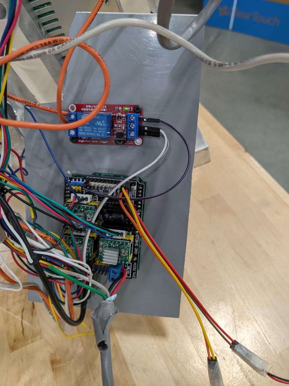
We connected the motor to the GRBL shield using a relay. The relay is simply a switch, that turns the spindle on or off. This relay works by allowing a 5v signal from the GRBL shield to turn on and off the spindle, which was providing 12v DC power. This relay allows the 5v signal to control the 12v powered spindle.
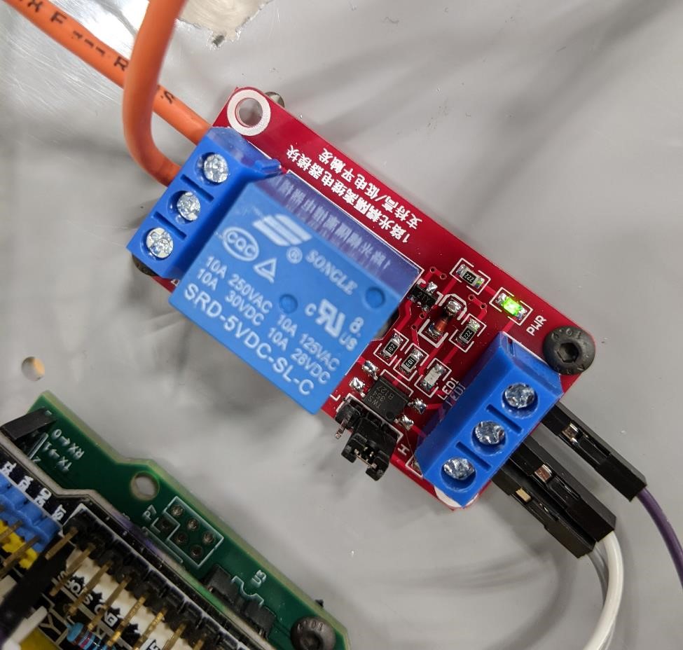
The wiring connection sends ground (white cable) directly from the power supply to the motor, and the 12v power supply to the input of the relay (on one side) and then a 12v power output to the spindle motor. The other side of the relay is connected to the GRBL shield with the “Spindle Enable” turning the relay on or off.
Hold and Cycle Start switches.
Because when you’re creating a new machine, you don’t know what’s going to happen, it’s really nice to have an emergency stop button or at least a feed hold.
We didn’t have any buttons at the moment, so we simply used the limit switches that we didn’t need, and hooked those up as our “Hold” and “Cycle Start” buttons. One issue is that our switches were “normally closed” switches (instead of “normally open”). Which is the opposite of what this GRBL shield was looking for. So they acted as a weird sort of Dead Man’s switch, and you had to hold the limit switch feed hold down for the machine to work. Annoying, but this is prototyping. These things happen.
Adam Harris mentioned that GRBL has changed a number of it’s pin assignments, and this is very likely to have been the reason behind this. We’ll deal with it later.
We’ll be adding real feed hold, cycle start, and e-stop switches later.
Software
For the software to control the machine, we used Universal Gcode Sender
We installed the software by following and downloading the Linux Arm (for the Raspberry Pi) files from this site: https://winder.github.io/ugs_website/download/
This is a basic g-code file sender, that has the ability to jog the axis of the machine around, setup the machine’s configuration (which way to turn the steppers for +/- direction, abiltity to set limits and range of movement, speed of machine, etc.)
This is a simple design, and has a setup wizard that helps you set things up, such as your stepper motor steps per mm, as well as limit switches, etc.
You can also create macros, such as one for turning on and off the spindle.
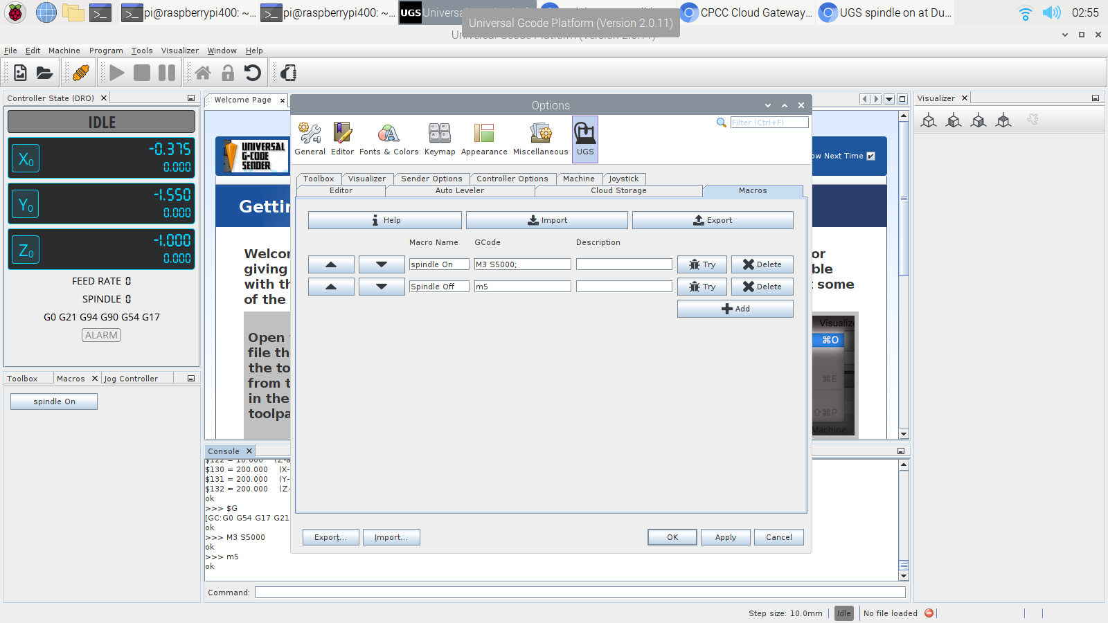
Here you can see the default window, where you can jog the machine, send the gcode, etc.
(For more information see: https://winder.github.io/ugs_website/guide/platform/)
GRBL has it’s own slightly modified system of sending commands. It has a fairly typical Gcode library, but as is always the case with Gcode, many manufacturers/systems have a slightly different gcode format that they use, so always look into this.
For more info on GRBL commands: https://www.cnc4fun.com/wp-content/uploads/2019/12/Grbl-Commands-v1.1-2.pdf
And as an aside, to help with seeing and writing gcode, we highly recommend NCViewer
Assembling the machine
The next day, we started full assembly…
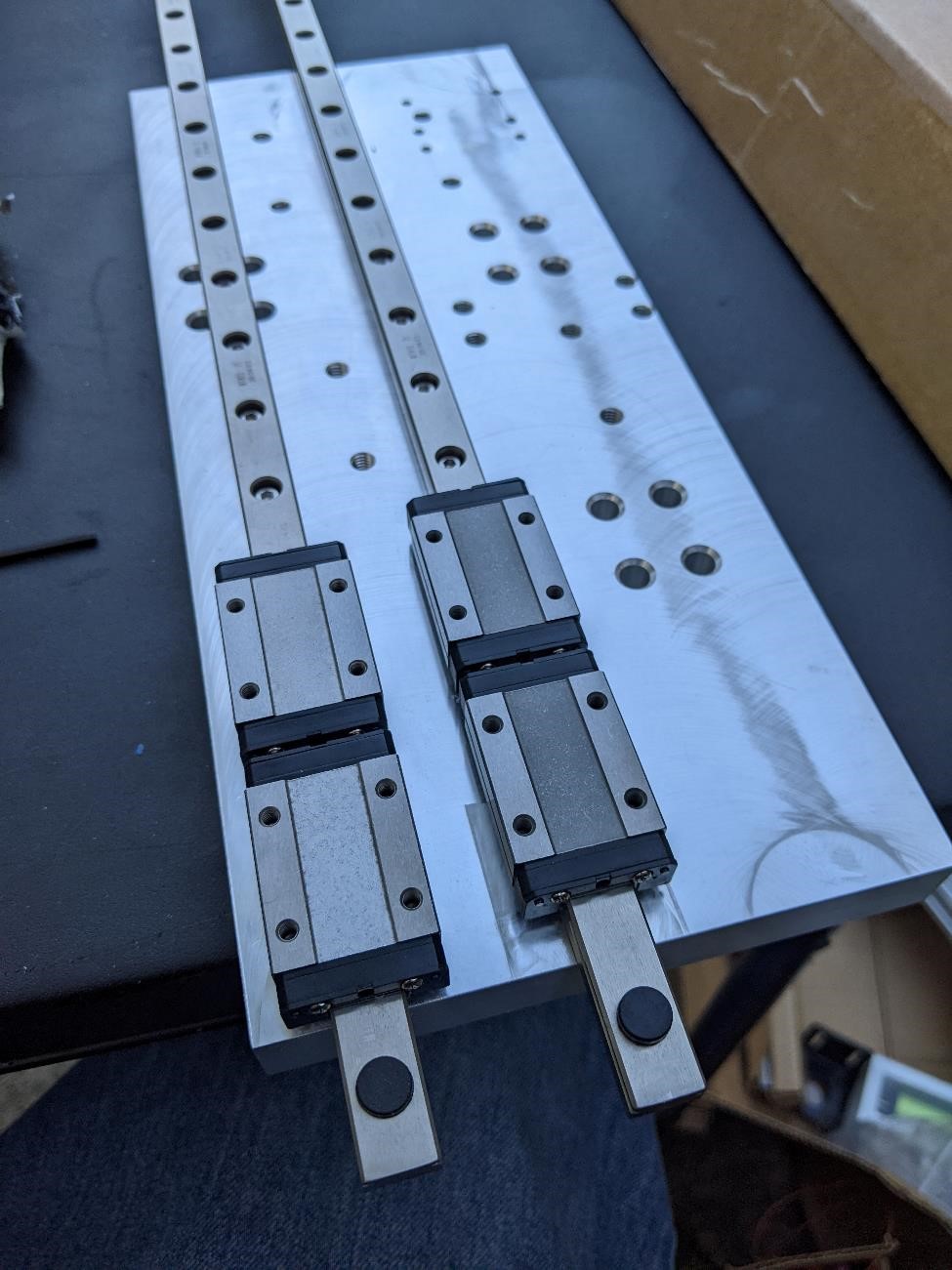
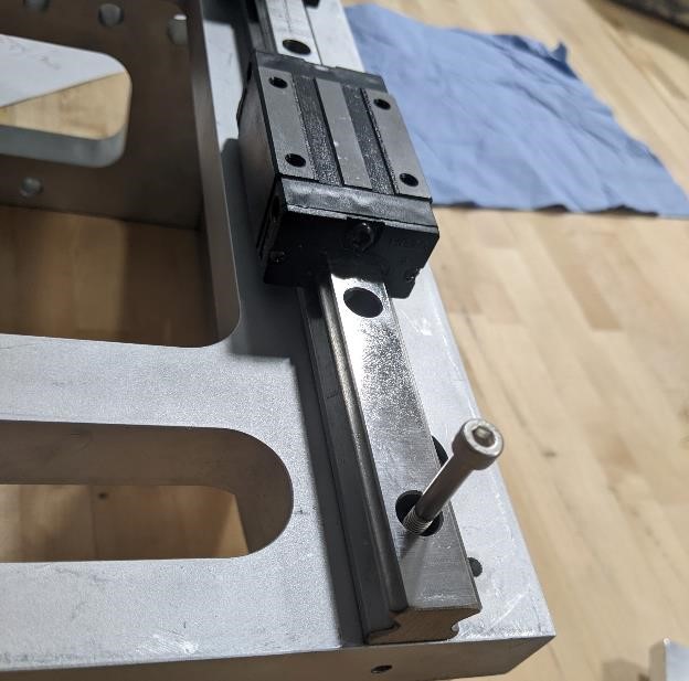
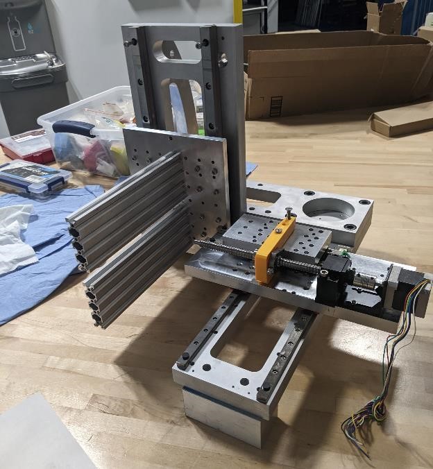
First, we added rails to the main body. With these rails, we need to make sure that they do not bind. There are different ways of going abot this. One quick and dirty way that gets acceptable results is to tighten one rail, place the carrige on both rails, and then run the carriage up and down the set of rails. This will hopefully help to at least align the rails to each other. Then you can tighten the 2nd set as you move the carriage. It’s not perfect, but it’s quick.
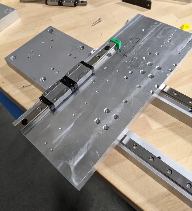
Here is the first carriage connected with rails

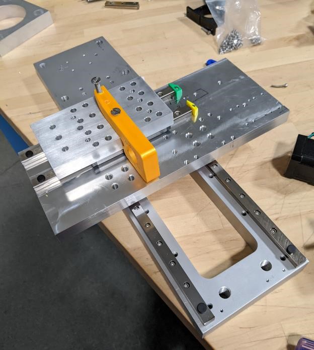
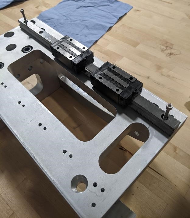
Then the second set of rails and second carriage is added.
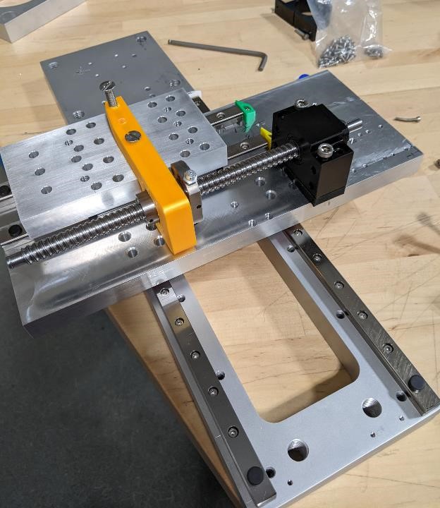
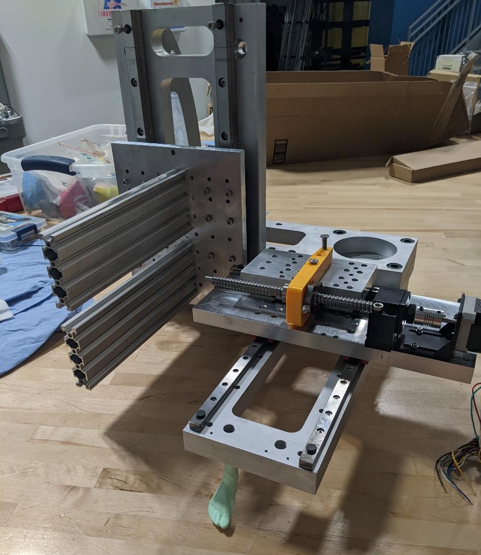
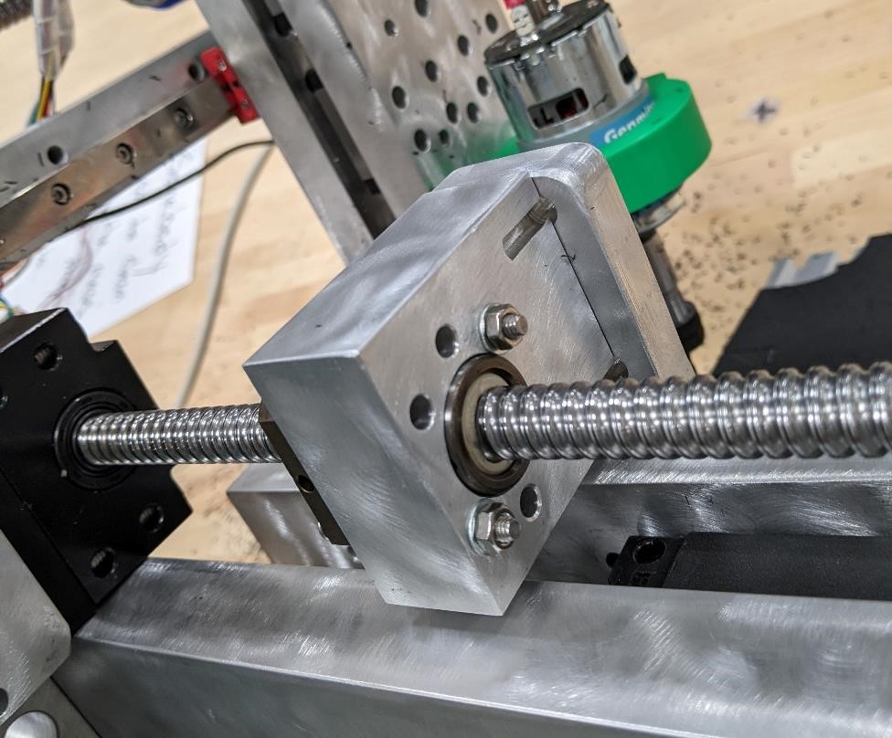
Then we start attaching the ballscrew and it’s accompanying bearing block.
Then we started to assemble the back of the main body, bolting the two pieces together.
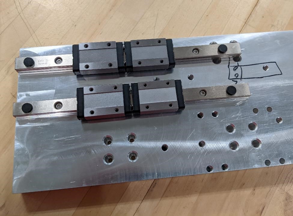
Here, we’re using an extra long bolt to act as a end stop to keep the rail carriers from sliding off. It’s not a permanent solution, but it’s to help while we’re manipulating and installing all the pieces.
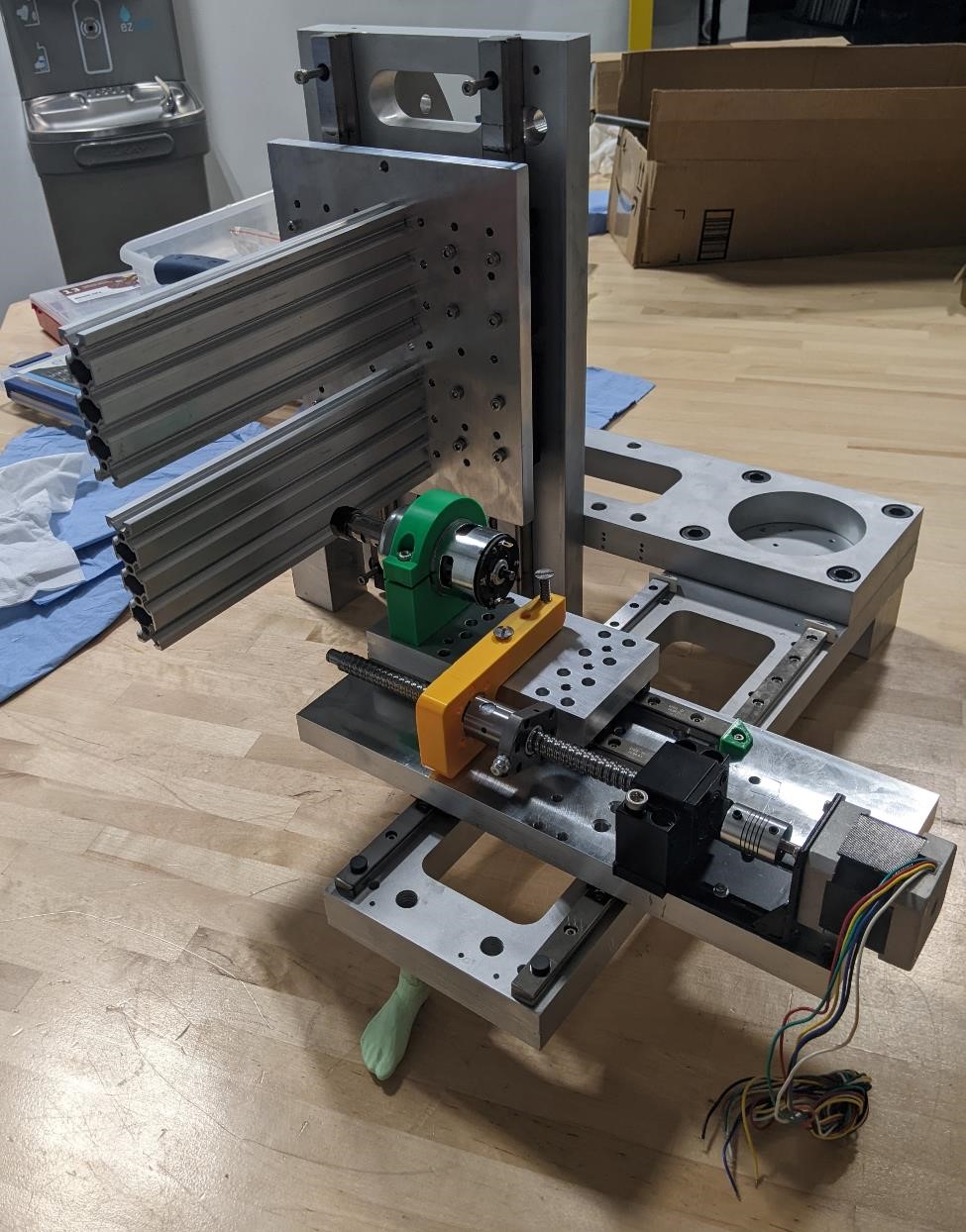
And then adding the last carriage to the rails on the vertical axis.
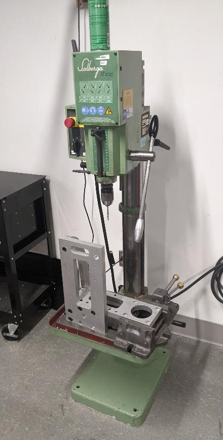
Occasionally we had to add features, fix things or make changes. Here we are using a drill press to small holes in the top of the vertical piece in order to mount stops and possibly future features.
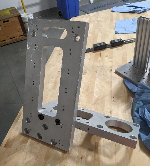
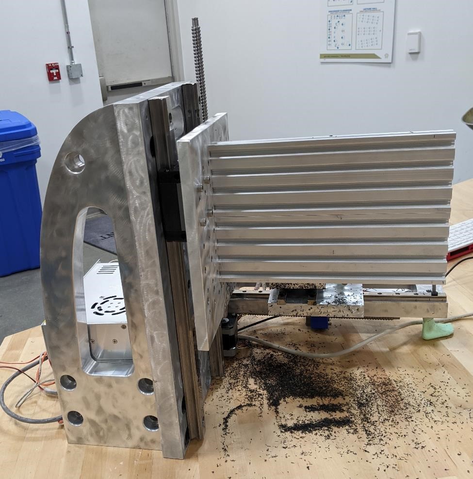
Next we attach the two major pieces. This can be tricky, and it’s helpful to have a friend or a good setup to balance the two parts.
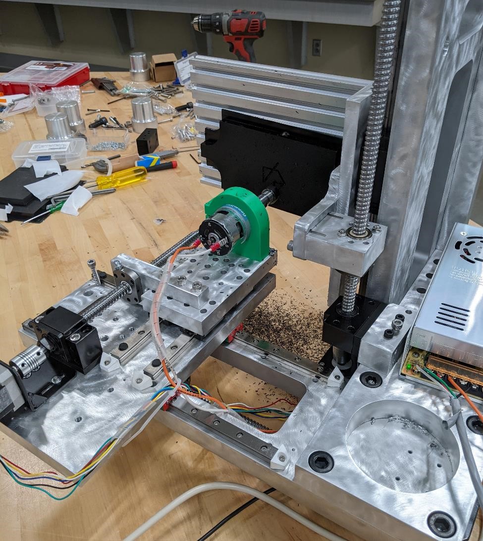
And we keep adding stepper motors, bearings, ball nut and ball nut carriages, the spindle, etc.
And finally, while not finished, we’ve made some progress.
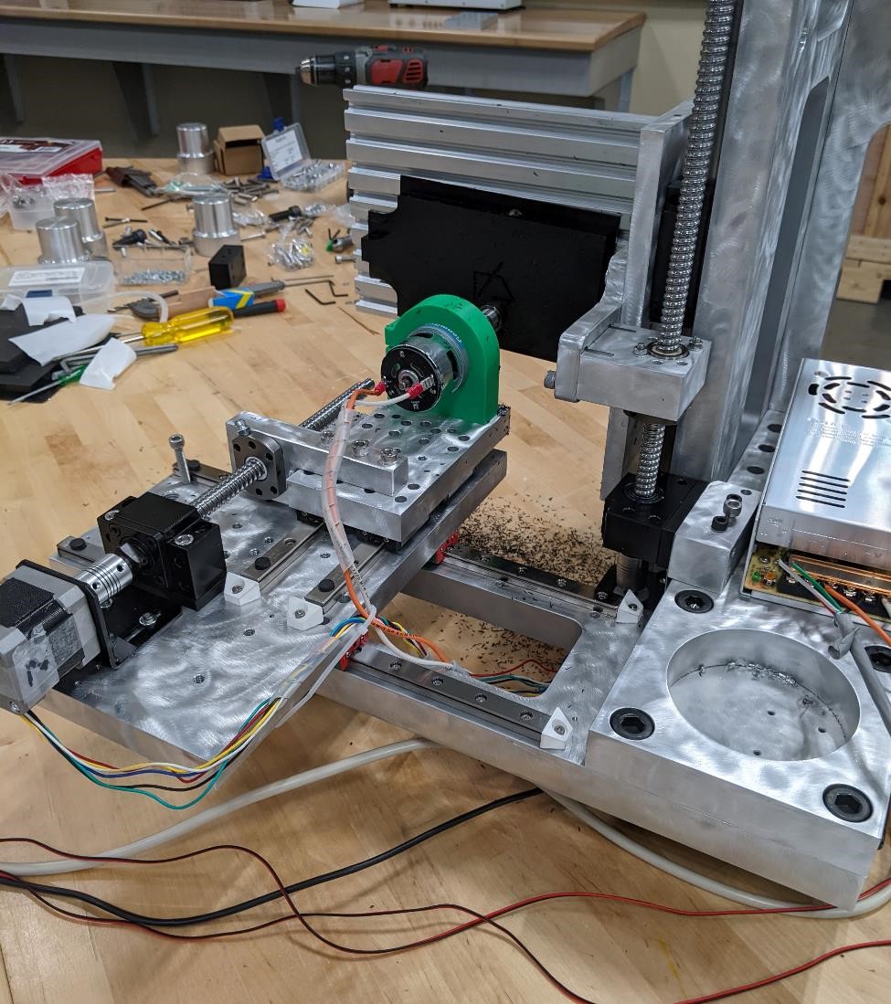
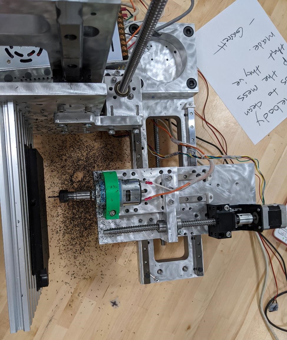
The below shots are from after it was completely assembled.
The underneath view showing the axis setup and electronics
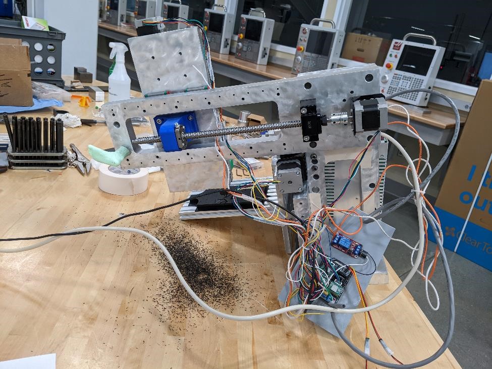
and another showing the 3d printed parts for the ballscrew nut connection
A backside view
And at the end of the day… Another Messy Shop
Finally getting close
Cori made sure that the project was aesthetically pleasing, as well as well documented. She’s got quite the future in Hollywood. (I see her as more of an independent filmmaker personally however -the editor.)
She gave the entire machine the awesome engine-turned, jewel like quality. It looks great.
She also did a large portion of the assembly, which could have gone smoother if she had better instructions, but some idiot had left them at home.
But, while many parts were assembled, there are always the small little things that break, need fixing, don’t work as expected, etc. etc. etc.
After a very very long weekend, and a very long Monday night, one of the team members finally hit the wall on Tuesday evening, the night before the project was due, and was unable to be much use to anyone. Unfortunately, this caused a number of issues and the project was essentially abandoned. Another team member was probably incredibly frustrated, and we decided to call it a night.
Rebirth of the F-Machine
And at this point, Garrett came up with it’s new name. No longer just the mini mill, now it’s the F-Machine. Because FabAcademy. Also because “F” this machine.
However, Adam Harris, stepped in, and helped us complete the project.
His help wasn’t necessarily in the technical side (though this was quite beneficial to be sure), but rather in simply helping to push us over the finish line (rather dragged would be more of an accurate description.) Without his encouragement, I’m sure this project would have not succeeded.
But with his help, both in the mental, as well as physical sense, the mill was able to make chips.
It was an incredibly arduous, error prone, hacked together, and strung together project. But in the end, it did cut.
It’s not great. It could use a lot of improvement. BUT. It works, and it was designed and built in two weeks, by a small group of people. It can be, and will be improved upon.
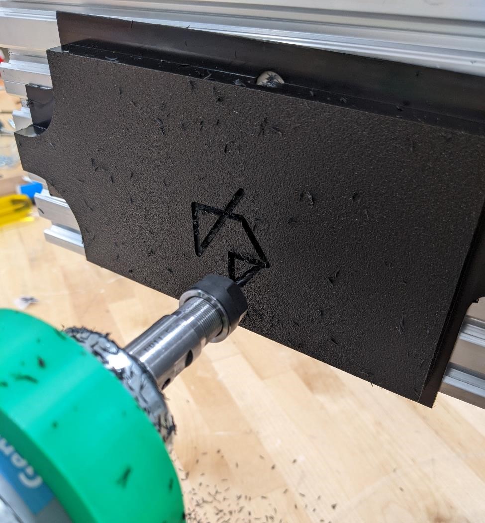
It’s alive!!
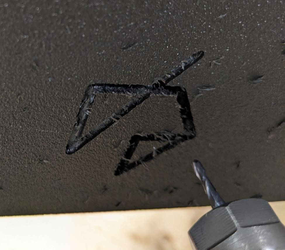
An engraved “F” for FabAcademy.
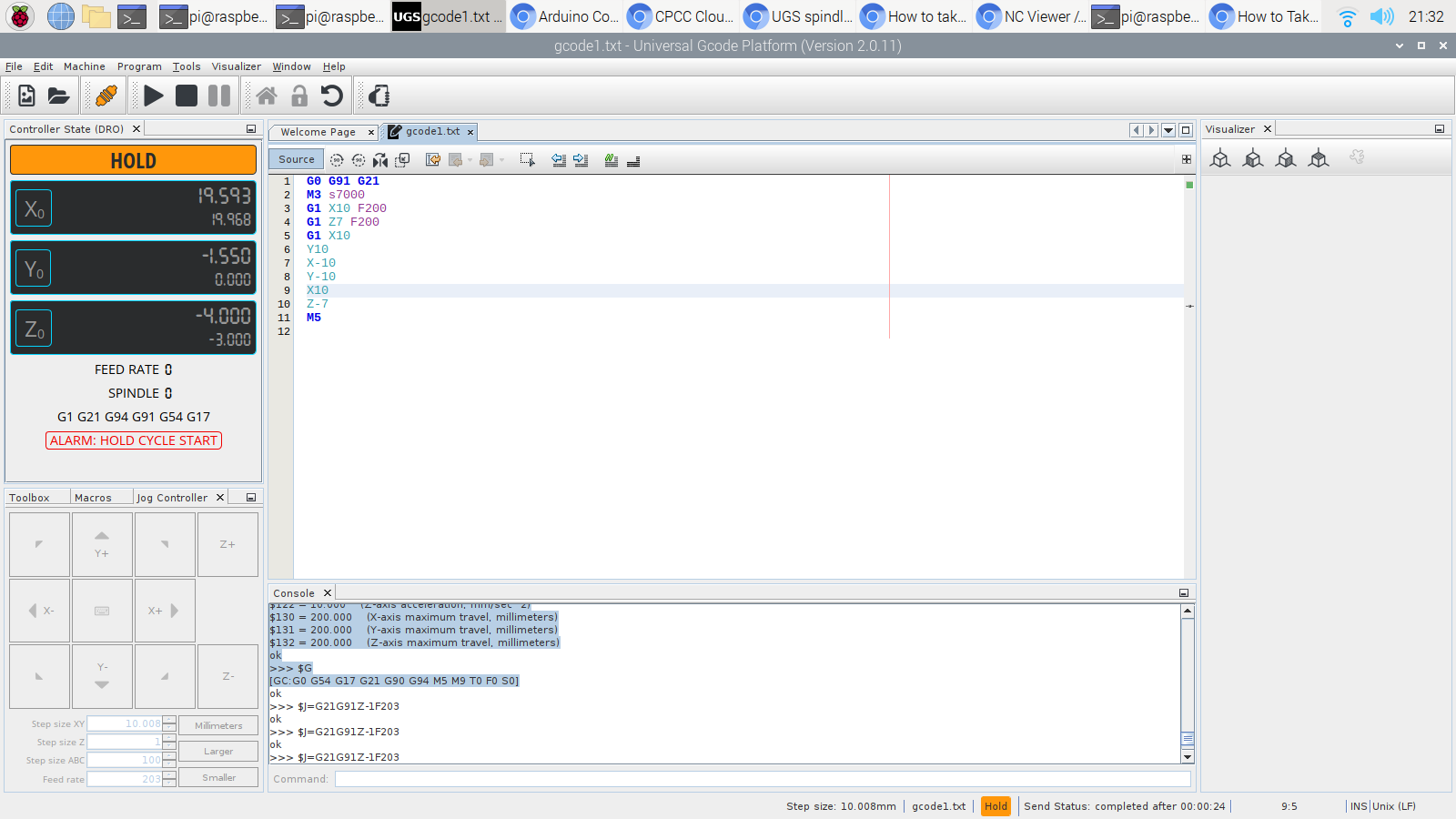
This was some random gcode that we hand typed at about 4:30AM, and while it’s not the prettiest, it’s enough to test the machine. The first gcode ran on the machine.
G0 g91 g21
m3 s7000
z7
g1 x30 y20 f200
x-20
y-20 z2
y-10 x15
y15
x14
y-13 x-13
z-10
m5
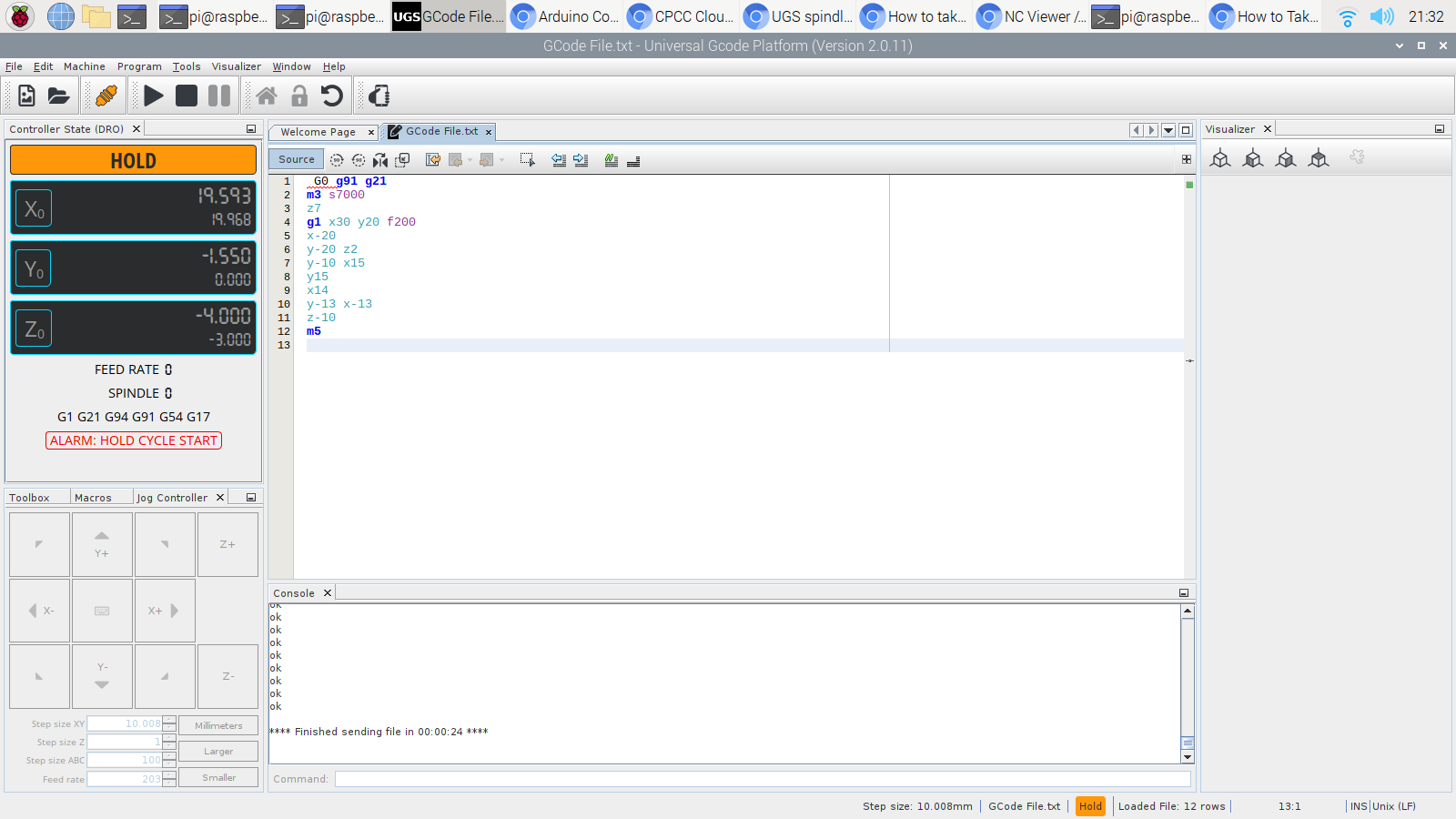
Here’s the command station to control the machine, a Raspberry Pi running Universal Gcode Sender. It’s not fancy, but it works.
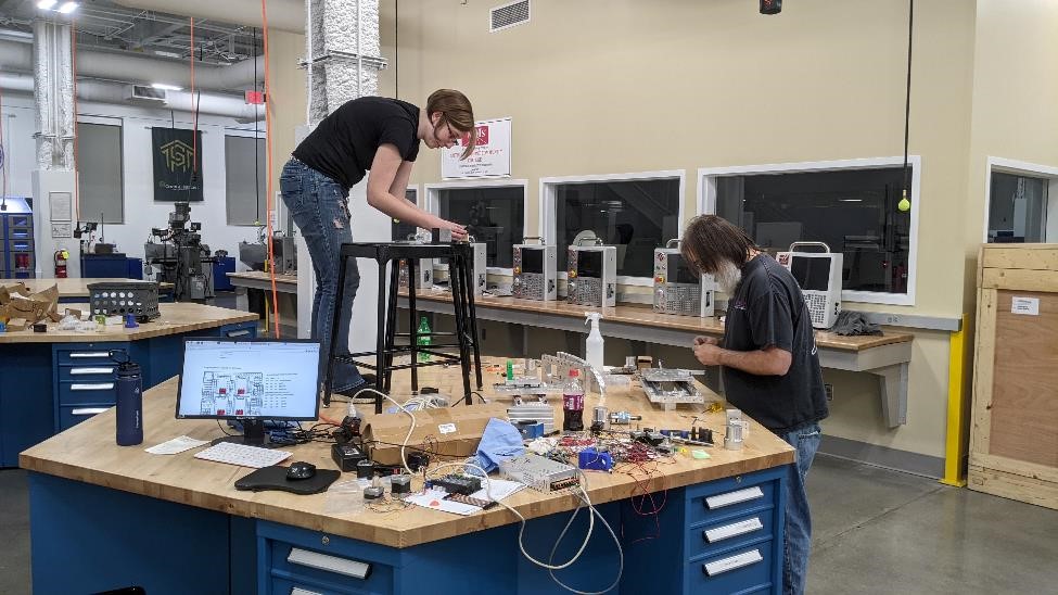
Cori and Garrett working on assembling the unit. Cori is taking photos for a timelapse.
Next…
Next up. Five Axis. I know Cori’s excited about spending more time on working on this project. She can’t wait!
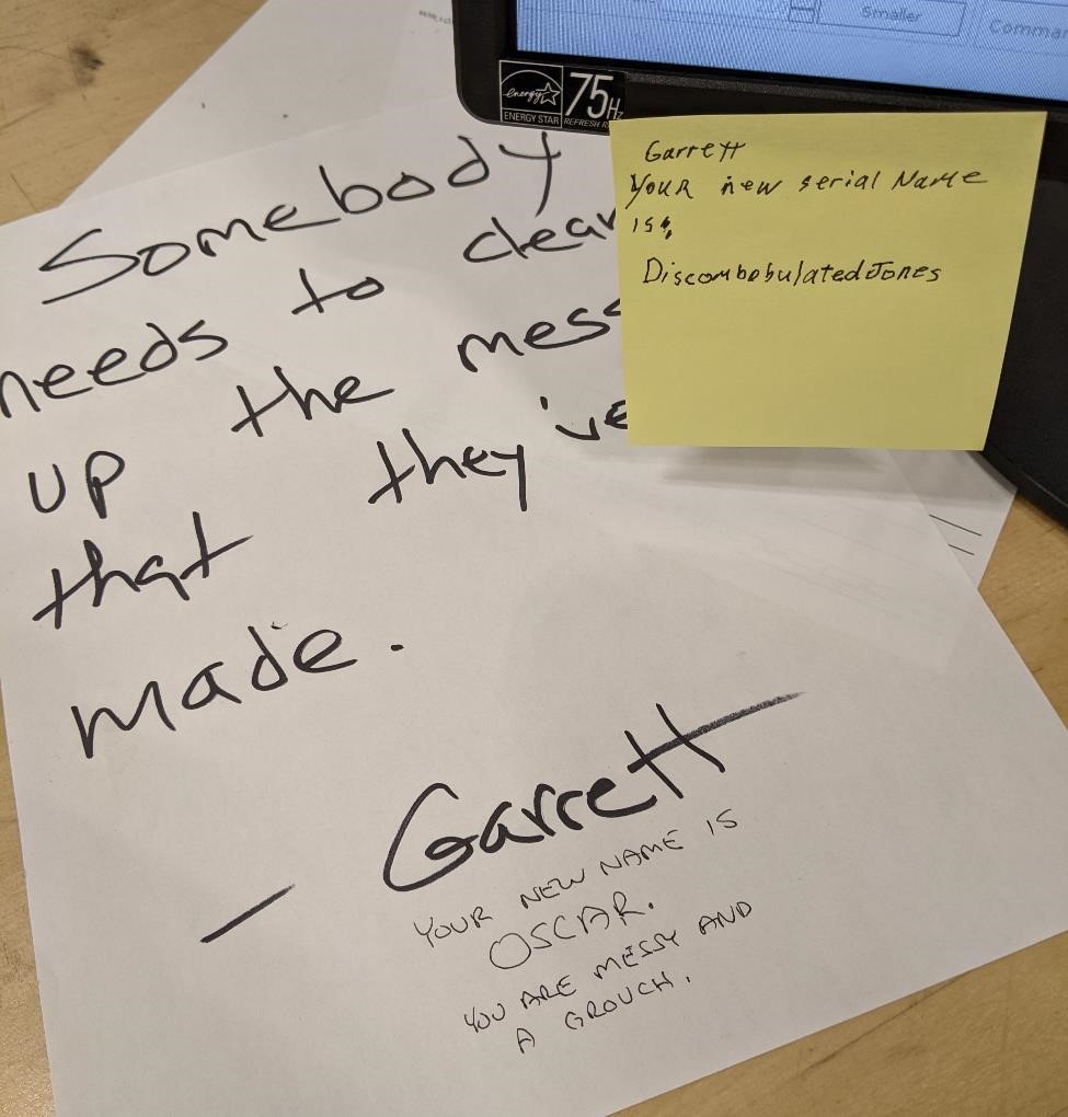
Garrett was very happy and had complete, fully functioning mental faculties during this entire process. You can tell by the notes that were left for him around the shop.
Thanks!
We got some extra help and support from friends, who provided their guidance, time and equipment and helped us carry on. These include Adam Harris (and his wife who allowed him to stay way too late to help us finish this project), Art Truss, Nick Nalley, Zach Lynn, Ross Peele, Denny Leak, David Taylor (who tapped his very first hole!), and a variety of others who if nothing else, provided us with moral support.
Notes and Issues
We ran into so many problems with this project. It’s not that it was unexpected, but we had a few more than I was prepared for. From one of our key group members dropping out, to the college being closed for 3 key days over the weekend due to the Easter Holiday, it really put us on our back foot.
There were too many times why we wondered why something wasn’t working, only to realize because we hadn’t plugged in the power supply. This happened way too often. Sleep is important.
Design Changes after Design Changes, after Design Changes
I don’t like major design changes, and I certainly don’t like them when it comes to a project with such a short time change. I keep any design to an absolute minimum, where it’s absolutely necessary and with as little impact on the rest of the design as possible.
Even when a design decision was just straight up bad, or at the very least sub-optimal, if the design was made, and changing it would impact major portions of the design, it was left as is, in order to create a functioning machine.
That said, because of the nature of this project, designing, ordering parts and manufacturing all simultaneously (which works so well for government projects), we ran into a number of other issues.
Many of them were Garrett’s mistakes for being tired and just making dumb mistakes. Some were overly relying on the “blueprints” randomly found online for parts, and then when the parts are delivered find that they’re not to the same spec, and thus requiring changes to already manufactured parts.
Some of the changes were due to what parts we had on hand, and what parts we could order and receive on time.
That said, here’s a small list of many of the things we had to change…
- Counterbores were deepend
- Holes for large linear rails were re-drilled, re-tapped for m5
- Holes were added to main table plate for metric sized extruded aluminum rails.
- Height of the ballnut connectors due to height of stepper motor mounts
- change in locations and heights of the ballscrew bearing blocks
- change in location of stepper motor because of said above change
- change in location and size of tapped holes for HGN20 linear rails (5mm instead of 6mm)
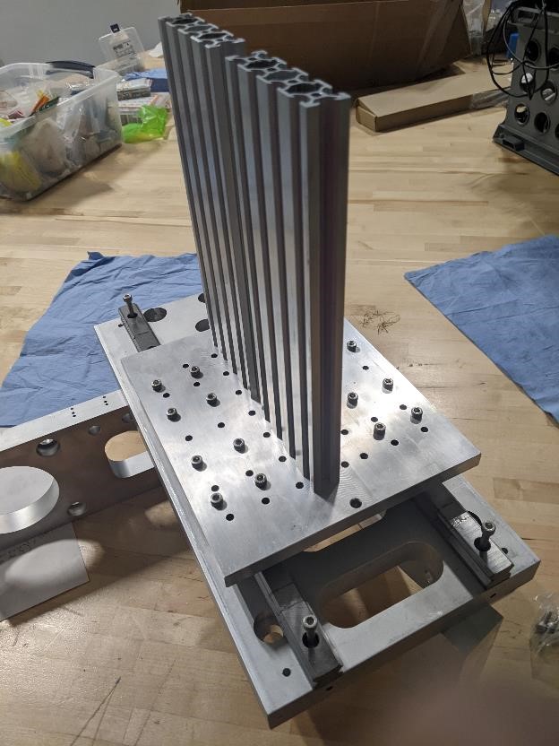
- added 20mm spacing to the vertical table plate for aluminum extrusion mounting.
- Adding extra holes for end stops and limit switches
- A thousand other things I can’t remember.
Hardware
We’re going to need:
- A lot of 1/2-13 1.5” bolts to hold the frame together.
- A whole lot of 3 mm, 5mm and 6mm SHCS of various lengths for holding the linear rails, rail blocks, bearing blocks etc to the frame.
- linear rails of the proper length
- ballscrews of the proper length and size (1204)
Electronics
We’re going to need:
- plugs for the servo motors to connect them to the GRBL shield
- An arduino
- Actual Servo Drivers (A948 or like)
- wiring all of these up
- limit switches
We’ve found a MKS board that we’ll most lilkely use with our machine, and it had stepper drivers.
We’ll be using GRBL and most likely Universal G-Code Sender
Spindle Motor Notes
On the Spindle Motor, from the listed Amazon page https://www.amazon.com/Genmitsu-GS-775M-20000RPM-Suppression-Electrical/dp/B08DTHDSMV/
Our spindle motor is a 24volt motor. The stepper motors will probably be 12v (though it’d be nice to use 24v with them.) We’re going to need to come up with a solution for this, which probably will just mean two power supplies. Not elegant, but it’ll work. (if we had a board with a 24v to a heated bed, could that work?)
We probably want a relay to be safe with this and the control board.
How do we control the motor speed?
Link on upgrading a spindle on 3018 https://www.youtube.com/watch?v=6kqmf_rWxs4
The way to get the new GS-775M spindle motor up to speed is to increment its runup using a sequence of GCODE commands. Those are shown here:

(Applies to new SainSmart Genmitsu GS-775M Spindle Motor)

(Spindle Speed 10000 RPM X 2; Set 10000 value for max spindle speed in Candle Settings)

(Ramp up spindle speed GCODE to prevent power supply overload)

M03 S1000

G4 P0.5

M03 S2000

G4 P0.5

M03 S5000

G4 P0.5

M03 S10000

(Spindle is now running at full speed)

This method is known to prevent overload of the power supply.

An alternative is to replace the stock power supply with one having greater current capacity (24V 8-10A), but that may burn out the controller with an abrupt 100% speed command.

However, a larger power supply should provide more cutting power from the GS-775M spindle, but the power-up sequence shown above is still recommended.
Things we wanted, but ain’t happening.
Some of the design aspects we would have loved, but couldn’t build due to time, budget, and skill restraints were:
- An granite epoxy frame for weight/damping (see: https://www.adambender.info/post/2017/03/25/epoxy-granite-machine-frame-how-to)
- Steel construction
- high quality ball screws
- scraped cast iron ways
- high quality servos with rotary encoders (or just steppers with closed loop system)
- high quality control board/system
- creating a 5 axis system.
- World Peace
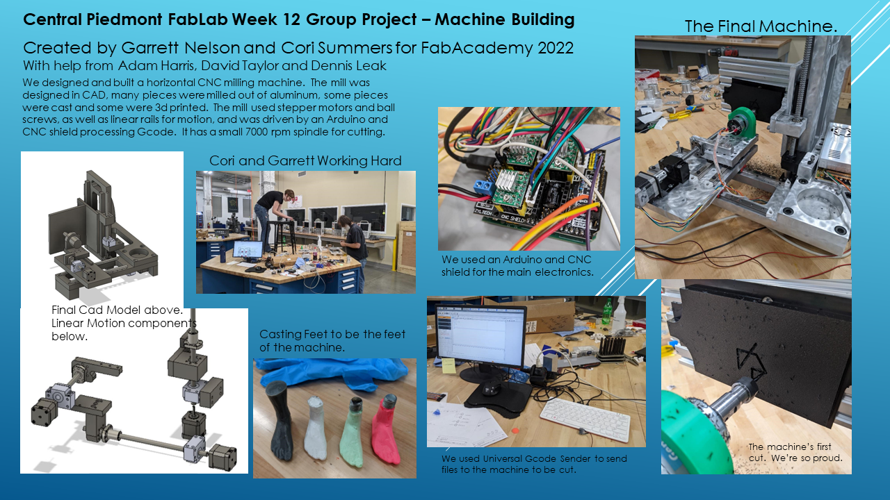
Group Project
You can find the group project page by clicking here
And the slide of our group project
What I contributed
I did a bit of the design work and machining. I also helped in the assembly process.
I almost won the award for most hand tapping of holes. It was a lot of holes.
What I learned
I need more sleep when working on big projects.
Files
Like so many of our projects, the files for this project take up 10’s of megabytes, too much to upload to the website. If you’re interested in these files, please contact us.
References
https://www.rahulsrajan.com/cnc-motion-controller-6e64f6
How to install and use GRBL: https://howtomechatronics.com/tutorials/how-to-setup-grbl-control-cnc-machine-with-arduino/
Tapping Guide: https://www.thingiverse.com/thing:512979/comments
CNC Shield and Arduino Guide https://www.zyltech.com/arduino-cnc-shield-instructions/
Using a Spindle with GRBL https://www.reddit.com/r/hobbycnc/comments/iwiaoe/controlling_spindle_speed_with_grbl/
Fusion 360 and GRBL https://www.autodesk.com/products/fusion-360/blog/fusion-360-grbl-post/
Setting up GRBL https://all3dp.com/2/gbrl-settings-gbrl-configuration/
GRBL configuration detailed data https://github.com/gnea/grbl/wiki/Grbl-v1.1-Configuration
Calibrating GRBL steps to MM https://diymachining.com/grbl-steps-per-mm/
More calibrating https://openbuilds.com/projectresources/howto-calibrate-your-cnc-machine-for-mach3-or-grbl.145/
Cori’s Great Gender Reveal
Congratulations Cori!