Work log - Week 16 - May 11, 2022
Wednesday 5/11
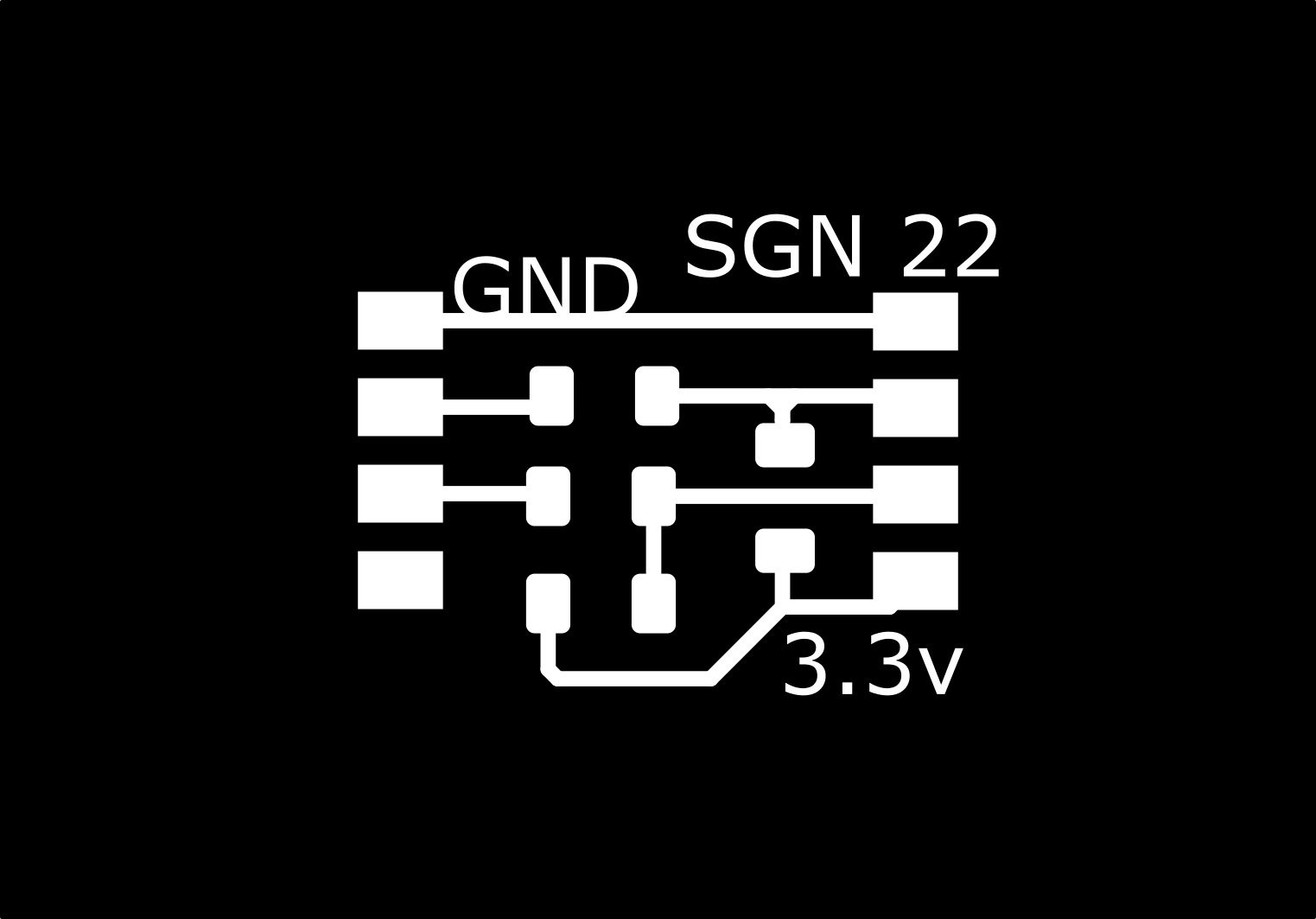
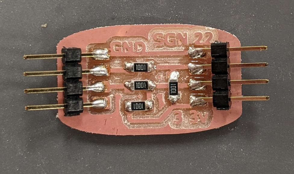
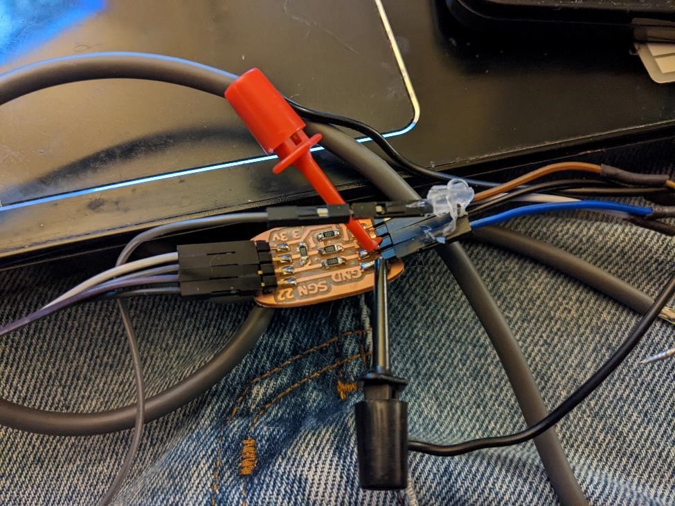
made breakout board for rotary encoder
ignores Z output. uses 1k resistors

Thursday 5/12
Neopixel test sketch for SAMD21 board and Arduino. It blinks the neopixel and normal led.
//https://github.com/adafruit/Adafruit_NeoPixel/blob/master/examples/strandtest/strandtest.ino
//and
//https://create.arduino.cc/projecthub/robocircuits/neopixel-tutorial-1ccfb9
// NeoPixel Ring simple sketch (c) 2013 Shae Erisson
// Released under the GPLv3 license to match the rest of the
// Adafruit NeoPixel library

#include <Adafruit_NeoPixel.h>
// NeoPixel Ring simple sketch (c) 2013 Shae Erisson
// Released under the GPLv3 license to match the rest of the
// Adafruit NeoPixel library


// Which pin on the Arduino is connected to the NeoPixels?
#define PIN        27 // Garrett Attiny Neopixel Board

int led = 23;  // normal led pin

// How many NeoPixels are attached to the Arduino?
#define NUMPIXELS 1 // only 1 on og board

// When setting up the NeoPixel library, we tell it how many pixels,
// and which pin to use to send signals. Note that for older NeoPixel
// strips you might need to change the third parameter -- see the
// strandtest example for more information on possible values.
Adafruit_NeoPixel pixels(NUMPIXELS, PIN, NEO_RGBW + NEO_KHZ800); // RGBW neopixel
//Adafruit_NeoPixel pixels(NUMPIXELS, PIN, NEO_GRB + NEO_KHZ800);  // Normal neopixel


#define DELAYVAL 300 // Time (in milliseconds) to pause between pixels

void setup() {

  pinMode(led, OUTPUT);
  pixels.begin(); // INITIALIZE NeoPixel strip object (REQUIRED)
  pixels.setBrightness(35); // about 1/3 brightness
}

void loop() {
  pixels.clear(); // Set all pixel colors to 'off'
  delay(DELAYVAL);
  digitalWrite(led, LOW);
  // IF RGB: pixels.Color() takes RGB values, from 0,0,0 up to 255,255,255
  // IF RGBW: pixels.Color() takes RGBW values, from 0,0,0,0 up to 255,255,255,255
  // Here we're using a moderately bright green color:
  pixels.setPixelColor(0, pixels.Color(20, 150, 100, 0)); // erase the last pixel value if not RGBW
  pixels.show();               // Send the updated pixel colors to the hardware.
  delay(DELAYVAL);             // Pause before next pass through loop
  pixels.clear();
  delay(DELAYVAL);
  digitalWrite(led, HIGH);
  pixels.setPixelColor(0, pixels.Color(150, 0, 200, 0));
  pixels.show();
  delay(DELAYVAL);
  pixels.clear();
  delay(DELAYVAL);
  pixels.setPixelColor(0, pixels.Color(0, 0, 150, 40));
  pixels.show();
  digitalWrite(led, LOW);
  delay(DELAYVAL);


}
Case for SAMD21 board
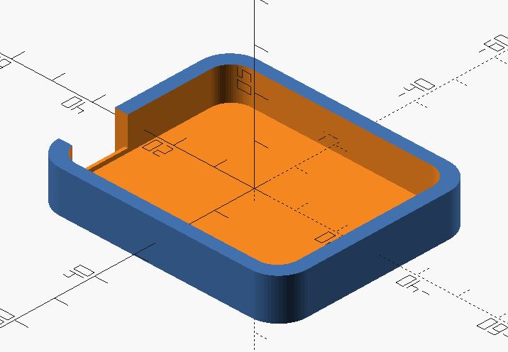
Here’s the OpenSCAD code for an open-faced case for this samd21 board.
//sgn may 2022
//samd21 board case for fabacademy

$fn = 64;

difference(){

minkowski(){
   translate([0,0,0])
   cube([47, 35.5, 6], center = true);

   cylinder(d = 14, h = 4, center=true);
}

minkowski(){

   translate([0,0,2])
   cube([44.5, 33.5, 6], center = true);

   cylinder(d = 10, h = 4, center=true);
}

translate([28,11,2])
cube([10, 14, 8], center = true);


translate([30,11,-1.1])
cube([4, 14, 8], center = true);
}
Circuit Python and SAMD21 board
This is based off of the board that can be found here: https://fabacademy.org/2022/labs/cpcc/students/garrett-nelson/about/worklog_wk15/#sunday-58
https://learn.adafruit.com/welcome-to-circuitpython
Next I wanted to see if I could get Circuit Python on my SAMD21E18A board.
I followed the directions and used the software from Quentin at: https://fabacademy.org/2020/labs/ulb/students/quentin-bolsee/projects/samd21e_devkit/
I downloaded his UF2 bootloader .bin file and his CircuitPython firmware .uf2.
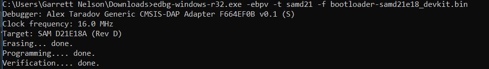
I then connected my board with the JTAG programmer, always make sure your programmer is set for 3.3v.
and flashed the UF2 bootloader using edbg.
edbg-windows-r32.exe -ebpv -t samd21 -f bootloader-samd21e18_devkit.bin
And then it’s time to connect it with your USB cable.
And hopefully you’ll see it as a mass storage drive when you open up a file explorer.
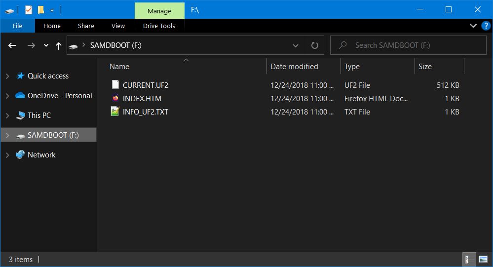
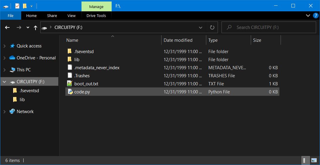
Now you can copy and paste the “firmware.uf2” file into this folder, and almost immediately, the folder will close and the device will restart and you’ll see it reappear as “CIRCUITPY”
Next, you can log in directly to this board using a Serial Terminal.
I’m using Windows, and I use puTTY.
But first, I need to know what COM port this is using.
I go to the Device Manager and look under “ports (COM & LPT)
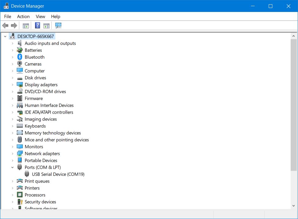
And seeing it’s COM19, I can open up puTTY, choose the “serial” option, type in COM19 and click “open”
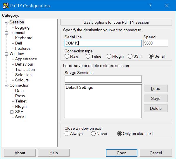
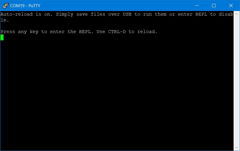
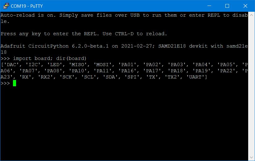
and you should now see the board open up, ready for your commands. If you press enter, you’ll get “REPL” the very basic python interpreter.
In the serial terminal, type:
print("Hello World")
And you should see the “Hello World” appear on the next line.
You’ve got Circuit Python running on your SAMD21 board.
Now you can open a text editor and write a blink program. (This code is from Adafruit’s Circuit python tutorial: https://learn.adafruit.com/welcome-to-circuitpython/creating-and-editing-code, I’ve massaged it a bit for my board.)
import board
import digitalio
import time

led = digitalio.DigitalInOut(board.PA23)
led.direction = digitalio.Direction.OUTPUT

while True:
    led.value = True
    time.sleep(0.3)
    led.value = False
    time.sleep(0.5)
Save the file as “code.py” on your CIRCUITPY drive. You should see the led start blinking.
Unfortunately, the version that Quentin used is 6.2beta, and the newest version is 7.0, where a number of large changes have been made, and newer libraries will likley not work with the old version (though, you can still find the older libraries, they are no longer udpated.)
I tried to get the neopixels running and could not due to the improper library (I could have hunted for the old library, but I’d rather upgrade the software.)
Updating Circuit Python for SAMD21e18 Boards
I did all the following on a raspberry pi 4 running raspbian linux.
And all of this comes from Quentin Bolsee, I’ve just modified it for my board which is slightly different. https://fabacademy.org/2020/labs/ulb/students/quentin-bolsee/projects/samd21e_devkit/
and you’ll find this helpful: https://learn.adafruit.com/building-circuitpython/build-circuitpython
First I cloned the Adafruit Circuitpython code from https://github.com/adafruit/circuitpython using a program called “git”.
git clone https://github.com/adafruit/circuitpython.git adafruit/circuitpython
I then changed to the circuit python folder to install sub-modules using a command called “cd” (which stands for “change directory”)
cd adafruit/circuitpython
and installed the sub-modules. This is going to take a few minutes, and download a ton of files. The “make” is typically used for compiling software.
make fetch-submodules
and you have to do this as well… install pip for python 3. “pip” is a tool to download, update and keep track of different libraries for Python. “Sudo” is super user, (ie root) and tells the computer to allow the user to do something they would normally not be allowed to do. You may have to provide the root password here. “Apt” is another library/software download tool.
sudo apt install python3-pip
then update the python files using pip.
pip3 install --upgrade -r requirements-dev.txt
pip3 install --upgrade -r requirements-doc.txt
Adafruit suggest installing pre-commit (I didn’t)
pip install pre-commit
pre-commit install
And I also installed these files, which are for compiling the code. This will take a while:
sudo apt install cmake gcc-arm-none-eabi build-essential libstdc++-arm-none-eabi-newlib
Then you have to make this… has something to do with libraries from micropython working with libraries from circuitpython… probably not necessary.
make -C mpy-cross
then I went to the folder where I downloaded the repository, and the “ports” folder, to the samd boards folder.
cd adafruit/circuitpython/ports/atmel-samd/boards
I made a new folder. “Mkdir” is “Make Directory.” and the folder name. This is where we’ll be editing and creating our new files.
mkdir samd21_sgn
and go to that directory
cd samd21_sgn
I used ‘nano’ a text editor to write the file ‘board.c’
nano board.c
Copy and paste the following. When done, press CTRL+O to save. CTRL+X will exit nano.
board.c
/*
 * This file is part of the MicroPython project, http://micropython.org/
 *
 * The MIT License (MIT)
 *
 * Copyright (c) 2017 Scott Shawcroft for Adafruit Industries
 *
 * Permission is hereby granted, free of charge, to any person obtaining a copy
 * of this software and associated documentation files (the "Software"), to deal
 * in the Software without restriction, including without limitation the rights
 * to use, copy, modify, merge, publish, distribute, sublicense, and/or sell
 * copies of the Software, and to permit persons to whom the Software is
 * furnished to do so, subject to the following conditions:
 *
 * The above copyright notice and this permission notice shall be included in
 * all copies or substantial portions of the Software.
 *
 * THE SOFTWARE IS PROVIDED "AS IS", WITHOUT WARRANTY OF ANY KIND, EXPRESS OR
 * IMPLIED, INCLUDING BUT NOT LIMITED TO THE WARRANTIES OF MERCHANTABILITY,
 * FITNESS FOR A PARTICULAR PURPOSE AND NONINFRINGEMENT. IN NO EVENT SHALL THE
 * AUTHORS OR COPYRIGHT HOLDERS BE LIABLE FOR ANY CLAIM, DAMAGES OR OTHER
 * LIABILITY, WHETHER IN AN ACTION OF CONTRACT, TORT OR OTHERWISE, ARISING FROM,
 * OUT OF OR IN CONNECTION WITH THE SOFTWARE OR THE USE OR OTHER DEALINGS IN
 * THE SOFTWARE.
 */

#include "supervisor/board.h"
#include "mpconfigboard.h"
#include "hal/include/hal_gpio.h"


void board_init(void) {
}

bool board_requests_safe_mode(void) {
    return false;
}

void reset_board(void) {
}
next I also wrote a file called “mpconfigboard.h” using nano and included the following:
mpconfigboard.h
#define MICROPY_HW_BOARD_NAME "SAMD21E18 sgn22"
#define MICROPY_HW_MCU_NAME "samd21e18"

#define MICROPY_PORT_A        (0)
#define MICROPY_PORT_B        (0)
#define MICROPY_PORT_C        (0)

// No microcontroller.nvm
#define CIRCUITPY_INTERNAL_NVM_SIZE 0

#define DEFAULT_I2C_BUS_SCL (&pin_PA17)
#define DEFAULT_I2C_BUS_SDA (&pin_PA16)

#define DEFAULT_SPI_BUS_SCK (&pin_PA19)
#define DEFAULT_SPI_BUS_MOSI (&pin_PA18)
#define DEFAULT_SPI_BUS_MISO (&pin_PA22)

#define DEFAULT_UART_BUS_RX (&pin_PA11)
#define DEFAULT_UART_BUS_TX (&pin_PA10)

#define IGNORE_PIN_PA12     1
#define IGNORE_PIN_PA13     1
#define IGNORE_PIN_PA20     1
#define IGNORE_PIN_PA21     1
// USB is always used.
#define IGNORE_PIN_PA24     1
#define IGNORE_PIN_PA25     1
#define IGNORE_PIN_PA30     1
#define IGNORE_PIN_PA31     1
#define IGNORE_PIN_PB01     1
#define IGNORE_PIN_PB02     1
#define IGNORE_PIN_PB03     1
#define IGNORE_PIN_PB04     1
#define IGNORE_PIN_PB05     1
#define IGNORE_PIN_PB06     1
#define IGNORE_PIN_PB07     1
#define IGNORE_PIN_PB08     1
#define IGNORE_PIN_PB09     1
#define IGNORE_PIN_PB10     1
#define IGNORE_PIN_PB11     1
#define IGNORE_PIN_PB12     1
#define IGNORE_PIN_PB13     1
#define IGNORE_PIN_PB14     1
#define IGNORE_PIN_PB15     1
#define IGNORE_PIN_PB16     1
#define IGNORE_PIN_PB17     1
#define IGNORE_PIN_PB22     1
#define IGNORE_PIN_PB23     1
#define IGNORE_PIN_PB30     1
#define IGNORE_PIN_PB31     1
#define IGNORE_PIN_PB00     1
and I then wrote the file “mpconfigboard.mk”
mpconfigboard.mk
USB_VID = 0x1B4F
USB_PID = 0x8D23
USB_PRODUCT = "SAMD21E18 sgn22"
USB_MANUFACTURER = "Fab Foundation"

CHIP_VARIANT = SAMD21E18A
CHIP_FAMILY = samd21

INTERNAL_FLASH_FILESYSTEM = 1
LONGINT_IMPL = NONE
CIRCUITPY_FULL_BUILD = 0

SUPEROPT_GC = 0
and finally, “pins.c” also using nano.
pins.c
#include "shared-bindings/board/__init__.h"

STATIC const mp_rom_map_elem_t board_module_globals_table[] = {
    // Digital pins
    { MP_ROM_QSTR(MP_QSTR_PA00), MP_ROM_PTR(&pin_PA00) },
    { MP_ROM_QSTR(MP_QSTR_PA01), MP_ROM_PTR(&pin_PA01) },
    { MP_ROM_QSTR(MP_QSTR_PA02), MP_ROM_PTR(&pin_PA02) },
    { MP_ROM_QSTR(MP_QSTR_PA03), MP_ROM_PTR(&pin_PA03) },
    { MP_ROM_QSTR(MP_QSTR_PA04), MP_ROM_PTR(&pin_PA04) },
    { MP_ROM_QSTR(MP_QSTR_PA05), MP_ROM_PTR(&pin_PA05) },
    { MP_ROM_QSTR(MP_QSTR_PA06), MP_ROM_PTR(&pin_PA06) },
    { MP_ROM_QSTR(MP_QSTR_PA07), MP_ROM_PTR(&pin_PA07) },
    { MP_ROM_QSTR(MP_QSTR_PA08), MP_ROM_PTR(&pin_PA08) },
    { MP_ROM_QSTR(MP_QSTR_PA09), MP_ROM_PTR(&pin_PA09) },
    { MP_ROM_QSTR(MP_QSTR_PA10), MP_ROM_PTR(&pin_PA10) },
    { MP_ROM_QSTR(MP_QSTR_PA11), MP_ROM_PTR(&pin_PA11) },
    { MP_ROM_QSTR(MP_QSTR_PA14), MP_ROM_PTR(&pin_PA14) },
    { MP_ROM_QSTR(MP_QSTR_PA15), MP_ROM_PTR(&pin_PA15) },
    { MP_ROM_QSTR(MP_QSTR_PA16), MP_ROM_PTR(&pin_PA16) },
    { MP_ROM_QSTR(MP_QSTR_PA17), MP_ROM_PTR(&pin_PA17) },
    { MP_ROM_QSTR(MP_QSTR_PA18), MP_ROM_PTR(&pin_PA18) },
    { MP_ROM_QSTR(MP_QSTR_PA19), MP_ROM_PTR(&pin_PA19) },
    { MP_ROM_QSTR(MP_QSTR_PA22), MP_ROM_PTR(&pin_PA22) },
    { MP_ROM_QSTR(MP_QSTR_PA23), MP_ROM_PTR(&pin_PA23) },
    { MP_ROM_QSTR(MP_QSTR_PA27), MP_ROM_PTR(&pin_PA27) },
    { MP_ROM_QSTR(MP_QSTR_PA28), MP_ROM_PTR(&pin_PA28) },

    { MP_ROM_QSTR(MP_QSTR_DAC), MP_ROM_PTR(&pin_PA03) },

    // UART pins
    { MP_ROM_QSTR(MP_QSTR_TX), MP_ROM_PTR(&pin_PA10) },
    { MP_ROM_QSTR(MP_QSTR_RX), MP_ROM_PTR(&pin_PA11) },
    { MP_ROM_QSTR(MP_QSTR_TX2), MP_ROM_PTR(&pin_PA14) },
    { MP_ROM_QSTR(MP_QSTR_RX2), MP_ROM_PTR(&pin_PA15) },

    // SPI pins
    { MP_ROM_QSTR(MP_QSTR_MOSI), MP_ROM_PTR(&pin_PA18) },
    { MP_ROM_QSTR(MP_QSTR_SCK), MP_ROM_PTR(&pin_PA19) },
    { MP_ROM_QSTR(MP_QSTR_MISO), MP_ROM_PTR(&pin_PA22) },

    // I2C pins
    { MP_ROM_QSTR(MP_QSTR_SCL), MP_ROM_PTR(&pin_PA17) },
    { MP_ROM_QSTR(MP_QSTR_SDA), MP_ROM_PTR(&pin_PA16) },

    // LED pins
    { MP_ROM_QSTR(MP_QSTR_LED),   MP_ROM_PTR(&pin_PA23) },

    // Comm objects
    { MP_ROM_QSTR(MP_QSTR_I2C), MP_ROM_PTR(&board_i2c_obj) },
    { MP_ROM_QSTR(MP_QSTR_SPI), MP_ROM_PTR(&board_spi_obj) },
    { MP_ROM_QSTR(MP_QSTR_UART), MP_ROM_PTR(&board_uart_obj) },
};
MP_DEFINE_CONST_DICT(board_module_globals, board_module_globals_table);
then I move up two folders (the ‘..’ are the folder above. One dot is the current folder. The slash is seperating, so it says go up two levels.)
cd ../..
and we’re going to compile the software using “make” for this specific board version.
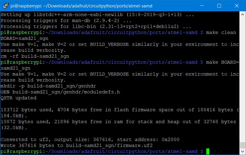
make BOARD=samd21_sgn
And after all of that… it compiled the firmware in about 5 minutes.
You can find the ‘firmware.uf2’ file under ‘build-samd21_sgn’
Circuit Python SAMD21 SGN Board Firmware
Here’s the firmware.uf2 file: firmware.uf2
for future reference: https://github.com/ladyada/uf2-samd21
Reloading new Circuit Python
Next, we need to upload this firmware.uf2 to our board.
I hit the reset button twice, which restores the original bootloader.
Then I can copy and past the firmware.uf2 file to the folder that was formerly CIRCUITPY.
You should then be able to upload a blink example, and it should start blinking.
working with neopixels and ciruitpython
The next thing is that I wanted the neopixels to work. I switched back to a windows computer for this step, but it’ll work in Linux too as long as you know your way around the usb device.
create a “lib” folder in the top level of the CIRCUITPY folder ( the main folder of your circuit python board)
Then download the adafruit-circuit-python-bundle-7.x-mpy-20220512.zip from https://circuitpython.org/libraries (this code was compiled by me on May 12th, 2022. I don’t know how future versions will work, keep this in mind.)
Unzip the file, and go into the “lib” folder.
Copy “neopixel.mpy” and “adafruit_pixelbuf.mpy” to the ‘lib’ folder on your CIRCUITPY board.
Then you can save this file as ‘code.py’ to your board. (simply write it in notepad or whatever and save it to the storage device “CIRCUITPY”.)
SAMD21 Circuit Python Blink for RGBW boards. If you need to change this to RGB, please refer to this reference: https://learn.adafruit.com/circuitpython-essentials/circuitpython-neopixel
import board
import digitalio
import time
import neopixel

led = digitalio.DigitalInOut(board.PA23)
led.direction = digitalio.Direction.OUTPUT
# set up for RGBW neopixels
pixels = neopixel.NeoPixel(board.PA27, 1, brightness=0.3, pixel_order=(1, 0, 2, 3))

while True:
    led.value = True
    pixels.fill((255, 0, 0, 0))
    pixels.show()
    time.sleep(0.5)
    led.value = False
    pixels.fill((0, 255, 0, 0))
    pixels.show()
    time.sleep(0.3)
    pixels.fill((0, 0, 0, 120))
    pixels.show()
    led.value = True
    time.sleep(0.5)
    pixels.fill((0, 0, 255, 0))
    pixels.show()
    led.value = False
    time.sleep(0.5)
It should start blinking.
Friday 5/13
Unfortunately didn’t have a chance to go in to CPCC today. Spent a lot of time today on documentation and catching up on things.
Update: Apparently Jenny and Cori were there and I missed seeing them. darn it.
Encoder problems
Also worked on trying to get rotary encoders to work with SAMD11 Board. I had no luck.
I made a circuit board that has both a pull up resistor (because of the rotary encoder’s signal was very low) and a current limiting resistor (that should protect the SAMD’s from current spikes). The board can be seen at the top of this page.
However, I used 1k resistors for all of the resistors, which I think I may have inadvertently created a voltage divider or something?
I put my crappy oscope on the inputs and outputs of the resistor board. On the side leading to the rotary encoder, I got exactly what I had hoped for, a much higher signal.
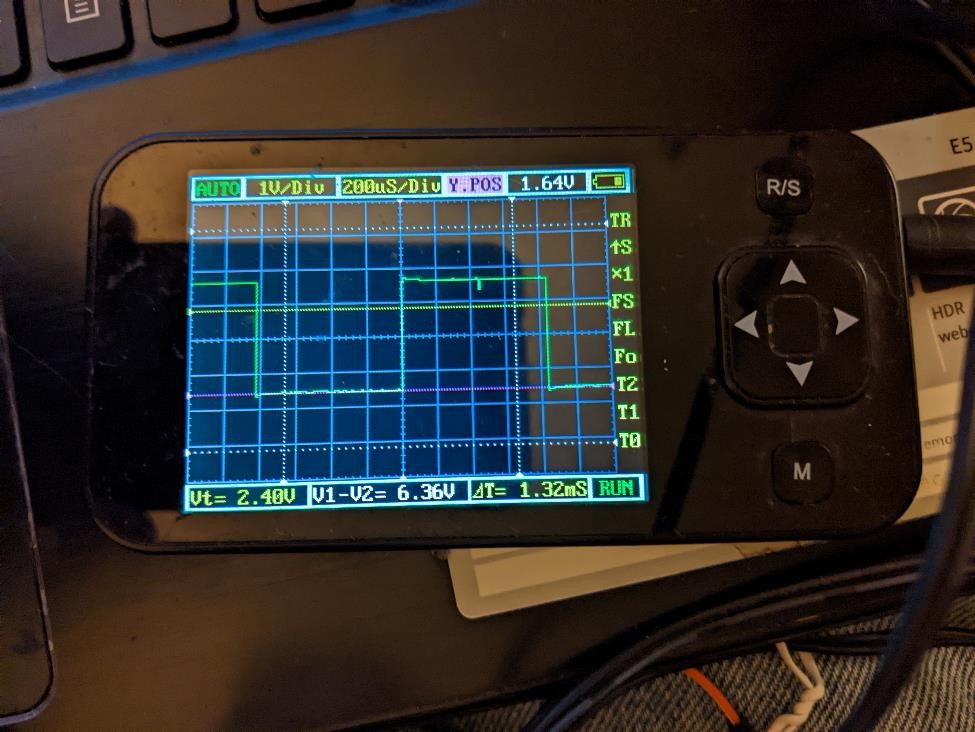
However, on the other side of the board, I’m seeing the signal which is maybe a signal of 0.5v peak to peak.
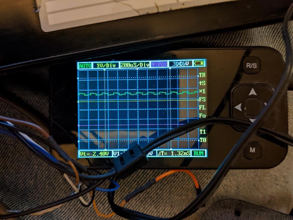
Right now I can’t even get any of the encoders to be picked up (using interrupts or polling) with the SAMD11 boards. I’m hoping this is because the signal is so low.
Saturday 5/14
Spent too much damn time working on the encoder trying to get it to work
Sunday 5/15
Started working on this week’s project, was told the embroidery machine was down, so started working on a 5 axis part.
Monday 5/16
Was in meetings most of the day, really didn’t get much accomplished. Fought with Fusion360 trying to get it to do 4 axis on a 5 axis. Wayyy too long to get this problem solved. It’s a dumb Fusion360 bug.
Tuesday 5/17
Fought with Fusion360 some more. Had to re-find Center of Rotation on Haas VF4, which is a lemon, finally made a part.