11. Output Devices
March 30 2022
This week we worked on creating output devices
![]()
Starting out with Neopixels
I dug a bit and found more information about what’s actually going on with the communication of neopixels: https://developer.electricimp.com/resources/neopixels
and:
https://wp.josh.com/2014/05/13/ws2812-neopixels-are-not-so-finicky-once-you-get-to-know-them/
I had created a number of neopixel boards in the preceding weeks, so I wanted to go further with getting more “data” out (that is, have more information provided) by the leds, other than just fancy colors.
I started here: https://learn.adafruit.com/adafruit-neopixel-uberguide/neomatrix-library
and I downloaded and installed these two libraries in the Arduino IDE.
The Adafruit NeoMatrix library
https://github.com/adafruit/Adafruit_NeoMatrix/archive/master.zip
and the Adafruit GFX library
https://github.com/adafruit/Adafruit-GFX-Library/archive/master.zip
And I had found this color code chart to help with choosing neopixel colors: https://www.rapidtables.com/web/color/RGB_Color.html
However, I discovered that since I wasn’t using the Adafruit_Neopixel.h library, but rather the version made for the ATtiny412, I was getting compilation errors, and I was starting to get into dependency hell. No thanks.
So I went back and looked for other, simpler examples. And… I didn’t really find anything that I found all that useful for trying to make a matrix like display, at least anything that I could understand and adapt given the time constraints.
![]()
Turquoise Wave
This is code for my 16 Neopixel Attiny412 that fills in each pixel, first vertically, while making each pixel more of a greenish tint, and then clearing each pixel horizontally. This is practice with for loops and better understanding how to control individual neopixels.
//https://github.com/adafruit/Adafruit_NeoPixel/blob/master/examples/strandtest/strandtest.ino
//and
//https://create.arduino.cc/projecthub/robocircuits/neopixel-tutorial-1ccfb9
// NeoPixel Ring simple sketch (c) 2013 Shae Erisson
// Released under the GPLv3 license to match the rest of the
// Adafruit NeoPixel library

#include <tinyNeoPixel.h>
// NeoPixel Ring simple sketch (c) 2013 Shae Erisson
// Released under the GPLv3 license to match the rest of the
// Adafruit NeoPixel library

// Which pin on the Arduino is connected to the NeoPixels?
#define PIN        4 // Garrett Attiny Neopixel Board

// How many NeoPixels are attached to the Arduino?
#define NUMPIXELS 16 // only 1 on og board

// When setting up the NeoPixel library, we tell it how many pixels,
// and which pin to use to send signals. Note that for older NeoPixel
// strips you might need to change the third parameter -- see the
// strandtest example for more information on possible values.
tinyNeoPixel pixels(NUMPIXELS, PIN, NEO_GRB + NEO_KHZ800);

#define DELAYVAL 100 // Time (in milliseconds) to pause between pixels

uint16_t i, j;
uint8_t n = 0;

void setup() {
  pixels.begin(); // INITIALIZE NeoPixel strip object (REQUIRED)
  pixels.setBrightness(25); // about 1/4 brightness
}

void loop() {
  pixels.clear(); // Set all pixel colors to 'off'
  // delay(DELAYVAL);
  // pixels.Color() takes RGB values, from 0,0,0 up to 255,255,255
  for(j=0; j < pixels.numPixels()/4; j++) {
     for(i=n; i < pixels.numPixels(); i = (i+4)) {
        pixels.setPixelColor(i, pixels.Color(0, (i*15+20) & 255, 20+(i*2)));
        delay(DELAYVAL);  //change DELAYVAL for speed increase/decrease
        pixels.show();
     }

  n++;  //keep track of how many times we cycle through everything. increment by one.
  }

  // this clears each pixel in it's turn.
  for(i=0; i < pixels.numPixels(); i++) {
     pixels.setPixelColor(i, pixels.Color(0, 0, 0));
     delay(DELAYVAL);
     pixels.show();
  }

  // this resets the pattern after 4 times.
  if (n == 4)
  {
    n = 0;
  }
}
Looking at the signals
This was my first test, at home, with a less than ideal setup.
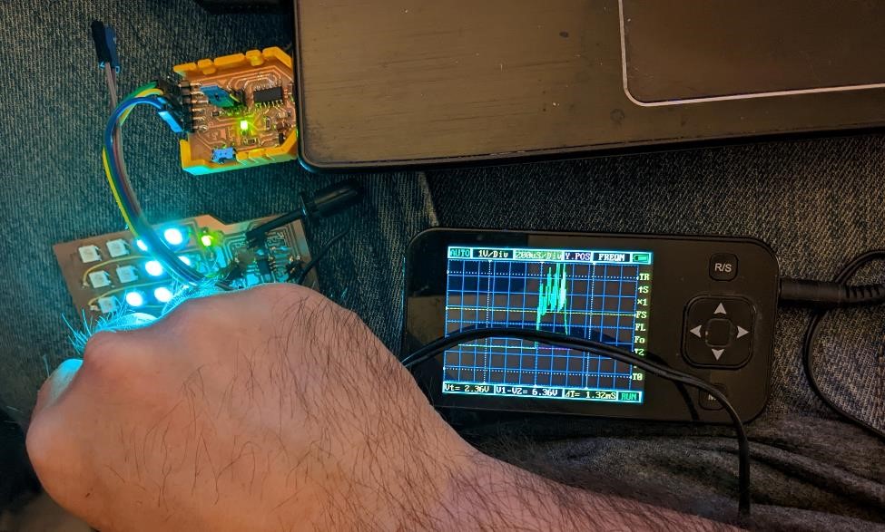
I learned some interesting things about Neopixels from trying them out with the O-scope.
What I observed on the first Neopixel’s data line was a large pulses (of what must have been serial data?). But as we went down and tested each neopixel, the pulse got shorter and shorter. And finally at the last Neopixel, there was no more pulse.
I found this interesting, and I theorized that it must be a serial data, and that the Neopixel’s must be somehow smart enough to only send the data needed for the neopixel’s after it, and not the entire data packet. Again, these are all assumptions, and we understand the limits of our knowledge in this area. But at the very least, it was a cool little thing to notice.
Later on, I took at look at some of the above referenced Neopixel pages and the data sheet and from my understanding, it looks like these assumptions were correct.
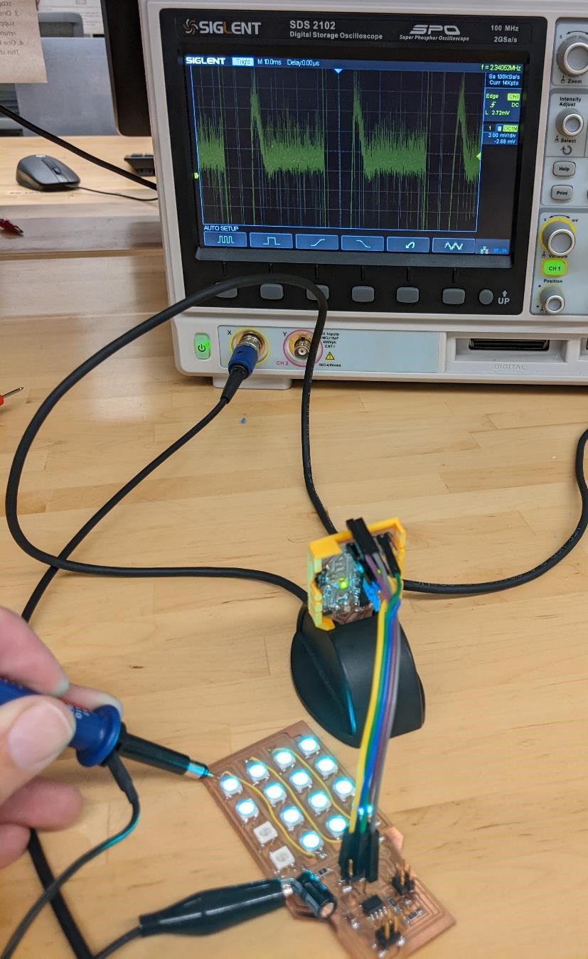
I did try to find the same data using a real O-scope later on, and noticed the same pattern, though it was bit more difficult to see on a “nice” oscilloscope rather than the cheaper, smaller one. I’d say this is probably user error.
Later on at the Fablab CPCC…
Power Output
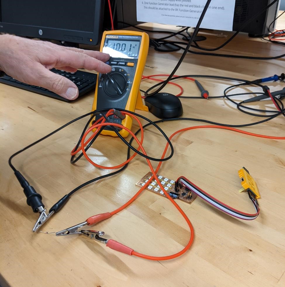
Later, Denny helped me with a multimeter to figure out the power consumption of this board.
(Images to be added soon)
We discovered that while running the above code (“Turquoise Wave” which is a low output blue wave that turns each LED on till they’re all on, and then turns each off, one at a time.)
This board was powered with 5v.
The current use was between 15mA at the lowest light level and 20ma with all neopixels on. We “Averaged” this out (just based on arverage).
So the Voltage (5v) multiplied by the current (17mA) equals 85mW of power consumption.
This turned out to be a power output of 85mW’s.
Adafruit doesn’t play well with ATtiny 412 and SAMD11C
One of the things I discovered this week is that having software support matters more than what hardware you’re using. I think it’s one of the things that has made the Arduino and Raspberry Pi popular. Knowing this now, I would have stuck with older Atmel 328 chips just I can expect there to be software support for them.
I tried to use the Adafruit NeoMatrix library with my Neopixels, and no go. Just errors with the libraries.
I tried to use the Adafruit_LEDbackpack library with a 8x8 LED matrix and I2C, and it kept complaining about SPI not being declared properly in the library. Again, no luck. I tried this on both a SAMD11C board and an ATtiny412 board.
And while this is input based, not output based, I ran into issues trying to compile the ADXL343 library from Adafruit for the SAMD11C and again, no luck.
I’ll design the boards. I’ll make the boards. I’m not writing a library for output devices in one week.
I’m just fed up with this. I’d rather use 10 year technology that I know works than relatively new chips with all the bells and whistles that have no support and thus are useless to me, a non-professional, no-electronics experience indivdual.
This week was a rather unsuccessful week. That’s just how it goes sometimes.
Files
![]()
![]()
Files for milling
![]()
![]()
Group Project
See our Week 11 - Output Group Project for more on this week’s group project.
I learned quite a bit about electronics this week. While I knew what Ohm’s law was, I honestly had no real practical use for it, nor had I really ever even used it outside of the classroom when I was in High School. For me it was just some magical formula that must have been important for everyone in electronics to always be using it, but I had no real understanding of.
But thankfully, Denny Leak was very patient with me and taught me quite a bit about electronic theory, but in a practical way, this week.
The first thing he did was to show me the way that Ohm’s law worked, by simply using a resistor and measuring the current through a 1k Ohm resistor powered by a 10v power supply. And doing the math of Ohm’s Law, I (current) = V (voltage) / R (resistance), that if we put 10v through a 1k ohm resistor so that I = 10v / 1000 ohms, that would be 0.01A (or 10mA).
And when we actually did this experiment, this is exactly what we discovered.
And when hooking up my neopixel board to the entire system, we also discovered a similar setup, that my board requires 85mA to run it’s current “wave” program.
But I now have a much better understanding of Ohm’s law, how to use it, and how to measure current in simple microcontrollers. There are still questions I have of shunt resistors and such when it comes to more powerful devices, but I’ll work on that later.
References and Resources
I did find some interesting resources, many listed above.
Attiny 412 and I2C: http://www.technoblogy.com/show?2QYB
How to scan I2C https://create.arduino.cc/projecthub/abdularbi17/how-to-scan-i2c-address-in-arduino-eaadda