Touch Probe Project
This was going to be a part of my final project, but on the suggestion of Neil and others, I dropped it from the final project. I include some of the information about it here for historical and design purposes.
Touch Probe
Rough Sketch
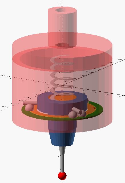
This is a rough outline of the basics of a touch probe. Created using OpenSCAD. Really ugly OpenSCAD code for this part can be found here: touch probe
Design - Touch Probe
This touch probe is based on the very early design of touch probes. It uses three sets of two ball bearings arranged 120 degrees from each other, with a metal rod resting the sets of balls. The rods are part of an insulating piece that also holds the probe tip at the bottom. This piece is held against the ball bearings by a low force spring. When at rest, these rods resting on two ball bearings (with each set connected to one another) completes a circuit. If the probe tip/stylus is moved, it will lift a metal rod, and the circuit is broken indicating a “touch.”
You can buy a touch probe for CNC mills for around $200. However, I wish to build my own for this project. I believe it is possible to build an accurate and repeatable touch probe, but it typically is necessary to have the high accuracy and surface finish of machined parts. Using 3d printers makes the creation of a touch probe more difficult (though certainly not impossible).
Touch Probe will have a 3d printed Main Body and Lid, a PCB “base plate” to hold six ¼” steel ball bearings (steel must be solderable, this is hard than it seems with ball bearings if they’re chromed, also due to high surface finish as well as high temperature sink. There is a special type of solder to help with this issue.)
The PCB can be easily and precisely milled to hold the ball bearings and to allow electrical connections to the bearings, as well as out to electronics. Spring (with adjustment screw at top) will provide tension to keep steel conductive rods between ball bearings unless a force is applied to probe tip. Probe tip will have three set screws in bottom of main case, that will hold up the pcb plate holding the bearings to allow for centering of probe tip. The three rod insulator and probe stylus/tip holder will be machined or 3d printed, and then an off the shelf ruby tipped probe stylus will be installed.
The electronics of the probe will consist of a simple de-bouncing circuit, a 5v led, and possibly 2 buttons to allow for control of the software (ie, one button to turn on probing, one to turn it off, or to cancel an inadvertent touch.)
Notes and challenges for touch probe:
- Like the arm itself, trying to make this reliable, repeatable, precise, and accurate are key, but may be difficult to reach goals that are sub 0.002” (0.050 mm).
- The three rod style probes are known to register “touches” with inconsistent pressure based on the direction that the touch probe tip is pushed. This is the nature of the system. Calibration helps with this. (see this paper for a reference and more information on strain gauges used in probes: https://resources.renishaw.com/en/details/technical-note-renishaws-strain-gauge-probing-technology--130 )
- Will need a way to zero and center the touch probe tip. “Easy” with a turning spindle and high accuracy dial test indicator. (Easy as in setup is easy, dialing it in, not so much.)
- Will need a way to calibrate the touch probe. A typical Ball Gauge on a mount, same as cartesian CMM may work well enough.
- Need to watch out for bouncing button issues of contacts – may need a debounce button setup https://docs.arduino.cc/built-in-examples/digital/Debounce
- Will need a 5v power supply for LED for contact notice. Helpful ui.
- If I add buttons, will need to add electronics, wiring for these buttons as well.
- Will want to shrink size dramatically, allow for larger maneuverability and ability to measure objects. This design used easy to source 1/4” ball bearings and 1/8” steel dowel rods, may want to switch to smaller diameter balls and rods.
Other design
- The plate for ball bearings holder for probe can be created as a pcb.
Off the shelf parts
For the Touch Probe:
- 1/8” diameter, 1” long dowel pins - 6
- ¼” ball bearings (non-chrome plated, 52200 steel may be best.)- 12
- ¾” diameter, 1” low force spring - 1
- Renishaw Probe Stylus (A -5000 – whatever) - 1
- Assorted hardware, set screws, nuts/bolts
Touch Probe Prior Art
Touch probe for small and diy CNC machines are common projects. I had previously created a touch probe, and so was aware of many of the designs already out there. These are some of the many resources available, and from which I have gotten information and ideas on how to design and construct my touch probe.
-
http://fadedbits.com/2011/02/touchprobe/
This is the probe that I’ve essentially based my entire design around. I think this is a very well designed and constructed probe.
-
https://www.instructables.com/CNC-Manual-Touch-Probe/
This is another design that was incredibly helpful. Very detailed instructions and gave me many ideas on the actual manufacturing. This also helped with the simple electronics and led. More information here: https://www.homemadetools.net/forum/homemade-renishaw-style-touch-probe-73121
-
https://lowpower.io/blog/introduccion-al-3d-touch-probe-para-cnc/
More information here: https://hackaday.io/project/168349-3d-touch-probe Where I stole the idea for the PCB ball bearing plate. This link also has links to other great videos on touch probes.
-
https://lukse.lt/uzrasai/2015-05-precise-steel-touch-probe-for-cnc-machines-routers/
I enjoy the design aesthetic.
-
https://forum.v1engineering.com/t/home-made-3d-digitizing-probe/18278/8
New to me, but very interesting design.
-
https://www.youtube.com/watch?v=_ZDlyLI_jbc
I love the clear case and LED
-
https://forum.duet3d.com/topic/8685/3d-scanning-a-2-coin-with-3d-printer-and-diy-touch-probe
This is just something different to throw in here. Showing using a tiny probe and 3d printer for a more “scanning” probe style setup.
A smaller probe using piezo’s: https://www.youtube.com/watch?v=xUk5MslH_nk&t=163s