Work log - Week 19 - June 1, 2022
Latest Versions of Software can be found here at the top.
New version of software for processing (pde file) can be found here
And
Here’s the latest version of the SAMD21 board encoder code (ino file)
(Ironically I’m not using git for this code, doing it the old fashioned way.)
Wednesday 6/1
The first few minuts of the class review were quite interesting, Neil was talking about internships and apprenticeships and working with companies who are interested in these skillsets.
https://finalprojects.fabacademy.org/#/schedule/2022
In class, went over Final projects we’ve gone over before; multiple times. Told “just make it work,” without any actul teaching, instruction, guidance. I could have actually been working on my project instead of class. Would have been more helpful.
For putting the Final Project slides and documents up on your website
“Not just with mkdocs. Also some html gitlab configurations require to have the documents not on the root,, but on the directory where your index is…” You may need to put the slide/videos in the “docs” folder.
From nueval “Prepare drafts of your summary slide (presentation.png, 1920x1080) and video clip (presentation.mp4, 1080p HTML5, 1 minute long) and put them in your root directory.” This is the exact thing needed, including file names.
Links
http://archive.fabacademy.org/fabacademy2017/fablabamsterdam/students/60/finalprojectpage.html
http://archive.fabacademy.org/archives/2017/fablabcci/students/411/
https://fabacademy.org/2022/labs/ulb/students/sylvain-denis/assignments/week09/#group-assignment
Murphy’s Law: https://authorchrisedwards.com/2021/05/17/1246/
Later
Spent much of today working on minor things, lots of documentation and filling in holes in past weeks. This took way too much time. Also had to do “real” work for much of the day.
Started learning more about polar coordinates and working on my programming skills trying to put the software together.
I was helped greatly by this video from Coding Train: https://www.youtube.com/watch?v=xXjRlEr7AGk, as mentioned in last week’s worklog
And I worked on the basic, 2d processing program that captured the data and showed a 2d model of the arm.
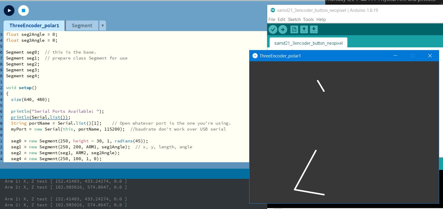
THe line in the top center indicated the rotation, and the lines on the bottom indicated the z and x positions (as they are.)
Thursday 6/2
Point Cloud Data
Time to start learning how to save this data in a point cloud data format…
There are so many different ones. I need one that is simple and can be easily converted to other formats.
For right now, if I can just save it as x, y, z coordinates, that’ll be good enough.
Some resources for this: https://info.vercator.com/blog/what-are-the-most-common-3d-point-cloud-file-formats-and-how-to-solve-interoperability-issues
So far it looks like I may use one of the following: OBJ, PLY, or PCD
Working on Trig
This was helpful video on trig and robotic arms: https://www.youtube.com/watch?v=NRgNDlVtmz0
Code for SAMD21 Board and 3 encoders.
Includes a button, minor neopixel support (just changes color when button is pushed.)
It’s not elegant, and it’s not the prettiest thing, but it works (mostly.)
// https://forum.arduino.cc/t/rotary-encoder-using-interrupts/469066/10
// This only sends data if the button on the board is pushed.
#include "Arduino.h"
#include <Adafruit_NeoPixel.h>
const byte encoderPinA = 4; //outputA digital pin4
const byte encoderPinB = 5; //outoutB digital pin5
const byte encoderPinC = 8; //outputC digital pin8
const byte encoderPinD = 9; //outoutD digital pin9
const byte encoderPinE = 19; //outputE digital pin19
const byte encoderPinF = 22; //outoutF digital pin22
volatile int count = 0;
int protectedCount = 0;
int previousCount = 0;
volatile int count2 = 0;
int protectedCount2 = 0;
int previousCount2 = 0;
volatile int count3 = 0;
int protectedCount3 = 0;
int previousCount3 = 0;
int buttonState = 1;
#define BUTTON_PIN 7
#define NEOPIXEL_PIN 27 // sgn SAMD21 Board
int LED_PIN = 23; // normal led pin
#define NUMPIXELS 1 // only 1 on board
// #define readA bitRead(PIND,2) // faster than digitalRead() For UNO
// #define readB bitRead(PIND,3) // faster than digitalRead()
#define readA digitalRead(encoderPinA)
#define readB digitalRead(encoderPinB)
#define readC digitalRead(encoderPinC)
#define readD digitalRead(encoderPinD)
#define readE digitalRead(encoderPinE)
#define readF digitalRead(encoderPinF)
//#define STATES_PER_REV1 4000
//#define STATES_PER_REV2 8000
Adafruit_NeoPixel pixels(NUMPIXELS, NEOPIXEL_PIN, NEO_RGBW + NEO_KHZ800); // RGBW neopixel
void setup() {
delay(10);
SerialUSB.begin(0);
delay(20);
pinMode(encoderPinA, INPUT);
pinMode(encoderPinB, INPUT);
pinMode(encoderPinC, INPUT);
pinMode(encoderPinD, INPUT);
pinMode(encoderPinE, INPUT);
pinMode(encoderPinF, INPUT);
delay(20);
attachInterrupt(digitalPinToInterrupt(encoderPinA), isrA, CHANGE);
attachInterrupt(digitalPinToInterrupt(encoderPinB), isrB, CHANGE);
attachInterrupt(digitalPinToInterrupt(encoderPinC), isrC, CHANGE);
attachInterrupt(digitalPinToInterrupt(encoderPinD), isrD, CHANGE);
attachInterrupt(digitalPinToInterrupt(encoderPinE), isrE, CHANGE);
attachInterrupt(digitalPinToInterrupt(encoderPinF), isrF, CHANGE);
delay(20);
pinMode(BUTTON_PIN, INPUT_PULLUP);
pinMode(LED_PIN, OUTPUT);
pixels.begin(); // INITIALIZE NeoPixel strip object (REQUIRED)
pixels.setBrightness(35); // about 1/3 brightness
pixels.show(); //turn off pixels
}
void loop() {
noInterrupts();
protectedCount = count;
protectedCount2 = count2;
protectedCount3 = count3;
interrupts();
buttonState = digitalRead(BUTTON_PIN); // read button pin
//send data over USB serial
SerialUSB.print(protectedCount);
SerialUSB.print(", ");
SerialUSB.print(protectedCount2);
SerialUSB.print(", ");
SerialUSB.print(protectedCount3);
SerialUSB.print(", ");
SerialUSB.println(buttonState);
pixels.clear(); //clear pixels, prepare for next color
if (buttonState == 0) { // if button pressed, turn on normal LED/neopixel to white
digitalWrite(LED_PIN, HIGH);
pixels.clear();
pixels.setPixelColor(0, pixels.Color(0, 0, 0, 250));
pixels.show(); // Send the updated pixel colors to the hardware.
} else {
digitalWrite(LED_PIN, LOW);
pixels.clear();
pixels.setPixelColor(0, pixels.Color(240, 0, 80, 0));
pixels.show(); // Send the updated pixel colors to the hardware.
}
delay(40); //so Processing can keep up.
previousCount = protectedCount;
previousCount2 = protectedCount2;
previousCount3 = protectedCount3;
}
void isrA() {
if(readB != readA) {
count ++;
} else {
count --;
}
}
void isrB() {
if (readA == readB) {
count ++;
} else {
count --;
}
}
void isrC() {
if(readD != readC) {
count2 ++;
} else {
count2 --;
}
}
void isrD() {
if (readC == readD) {
count2 ++;
} else {
count2 --;
}
}
void isrE() {
if(readF != readE) {
count3 ++;
} else {
count3 --;
}
}
void isrF() {
if (readE == readF) {
count3 ++;
} else {
count3 --;
}
}
```
### Physical Arm and pinouts.
UPDATE: THE BELOW IS OUTDATED AND HAS BEEN CHANGED
First arm (middle) is pins 4,5, segment 1 in Processing.
Second Arm (end effector) is pins 8,9, segment 2 in Processing
Rotary Axis is pins 19,22, segment 3 in Processing.
Button is pin 7
When data is sent to Processing, it is sent in the following order:
First Arm, Second Arm, Rotary Base, Button.
Don't know if it makes sense to put it all in that order, but it is what it is.
### This was awesome - 3d Arm modeling in Processing
This is exactly what I was looking for, and has been very helpful. (Hope the link works, it's got Kanji in it. It's been breaking mkdocs.)
[Nekodigi link](https://nekodigi.hatenablog.com/entry/2020/01/20/%E3%80%90Processing%E3%80%91ForwardKinematics%E3%81%A7%E3%83%AD%E3%83%9C%E3%83%83%E3%83%88%E3%82%A2%E3%83%BC%E3%83%A0%E3%82%92%E5%8B%95%E3%81%8B%E3%81%99)
Also found this video on forward kinematics very helpful: <https://www.youtube.com/watch?v=NRgNDlVtmz0>
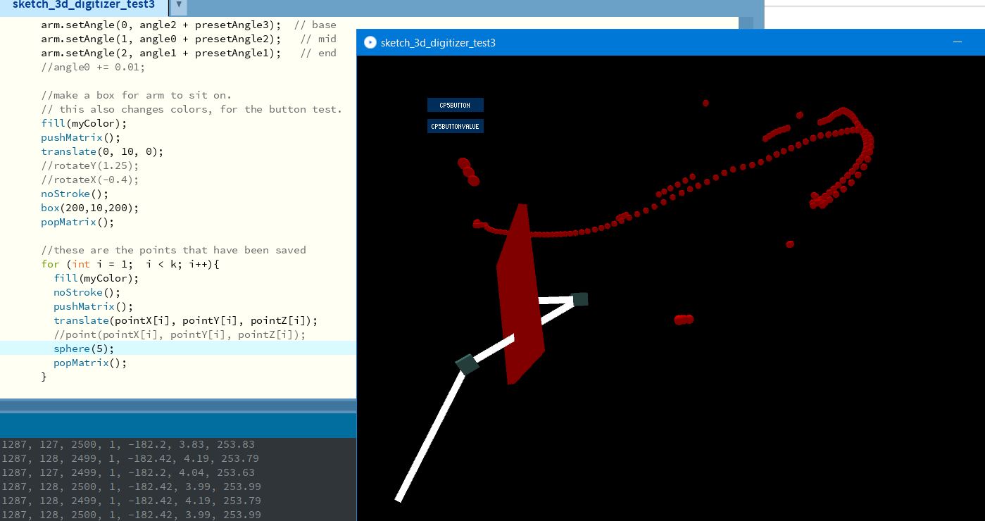
### And the Processing Code for a 3d arm based off the data from my rotary encoders
It may not look like it, but this is in 3d.
{: width="600" }
import processing.serial.*; // import library to handle serial port
float BASE = 100; // Base height in mm float ARM1 = 150; // Arm Segment 1 length in mm float ARM2 = 150; // Arm Segment 2 length in mm
float STATES_PER_REV = 2000; //Encoder half of number of counts per revolution. Why half?
Serial myPort; // Create object from Serial class String val; // Data received from the serial port
String[] encoders; // arrays to hold encoder data temporarily
int seg1Value = 0; // direct value from encoders int seg2Value = 0; int seg3Value = 0;
int button_state = 0;
Arm arm; // call the Arm Class
float angle0; // Prepare the angle variables
float angle1;
float angle2;
float previousAngle0; // Prepare the angle variables
float previousAngle1;
float previousAngle2;
void setup() { //frameRate(60); size(1000, 680, P3D);
println(“Serial Ports Available: “); println(Serial.list()); String portName = Serial.list()[1]; // Open whatever port is the one you’re using. myPort = new Serial(this, portName, 115200); //baudrate don’t work over USB serial
strokeWeight(10); arm = new Arm(new PVector(0, 0)); arm.addBone(BASE, 0); arm.addBone(ARM1, 2); arm.addBone(ARM2, 2);
myPort.bufferUntil(‘\n’);
}
void draw(){ background(0); lights(); if ( myPort.available() > 0) { // If data is available, val = myPort.readStringUntil(‘\n’); // read it and store it in val if(val != null) { // because processing likes to shit itself with nulls when reading serial. //println(val); // print the value we’re receiving from serial port
    encoders = trim(splitTokens(val, ","));  //split on comma

    seg1Value = int(encoders[0]);
    seg2Value = int(encoders[1]);
    seg3Value = int(encoders[2]);
    button_state = int(encoders[3]);
    /*
    print(seg1Value);  // for testing, as always.
    print(", ");
    print(seg2Value);
    print(", ");
    print(seg3Value);
    print(", ");
    print(button_state);
    println(" ");
    */
  }
}
    angle0 = seg1Value * PI * 2 / (STATES_PER_REV * 4);  // * 4 due to different encoders
    angle1 = seg2Value * PI * 2 / (STATES_PER_REV * 4);
    angle2 = seg3Value * PI * 2 / (STATES_PER_REV * 4);  //turn into degrees
    print(angle0);  // for testing, as always.
    print(", ");
    print(angle1);
    print(", ");
    print(angle2);
    println(" ");


    //float angle1 = (float)mouseX/500;
    //float angle2 = (float)mouseY/500;
    translate(width/2, height - 50);
    arm.show();
    arm.setAngle(0, angle2);  // base
    arm.setAngle(1, angle0);   // mid
    arm.setAngle(2, angle1);   // end
    //angle0 += 0.01;
}
class Arm {
ArrayList
void addBone(float len, int type){ if(bones.isEmpty()){ bones.add(new Bone(len, type)); } else { bones.add(new Bone(bones.get(bones.size()-1), len, type)); } }
void setAngle(int index, float angle){ bones.get(index).angle = angle; }
void show(){ pushMatrix(); translate(pos); for (Bone bone : bones){ bone.show(); } popMatrix(); } }
class Bone { Bone parent; int type; // 0 ==yaw, 1 = pitch, 2 = roll float len; float angle;
Bone(float len, int type){ this.len = len; this.type = type; }
Bone(Bone bone, float len, int type){ this.parent = bone; this.len = len; this.type = type; }
void show(){ noStroke(); box(20); if(type == 0){ rotateY(angle); } else if (type == 1) { rotateX(angle); } else if (type == 2) { rotateZ(angle); } stroke(255); line(0, 0, 0, 0, -len, 0); translate(0, -len, 0); noStroke(); //box(20); } }
void translate(PVector p) { rotateX(p.x); rotateY(p.y); rotateZ(p.z); }
void line(PVector a, PVector b){ line(a.x, a.y, a.z, b.x, b.y, b.z); } ```
Friday 6/3
Had to spend time on chores, spent time hanging out with neighbors.
But I got a lot done on programming tonight.
Right now, this software is useless if it doesn’t receive serial data. I should fix that, but it’s not like it’d be useful without the data anyways. But right now it’ll just crash. Should have it so it doesn’t do that.
new version of software for processing (pde file) can be found here
For the program, it now:
- displays the arm location in 3d
- gets the location of the tip and rotary encoders from the board
- get and store point location when the button is clicked
- display the saved points as dots
- changes colors a bit
- 3d camera, so you can rotate around the space
- includes buttons to change colors, save (save not working yet.)
- and a few other things.
Like always, writing out a list like this seems underwhelming, but it took a lot of time to get here.
Saturday 6/4
Processing Program
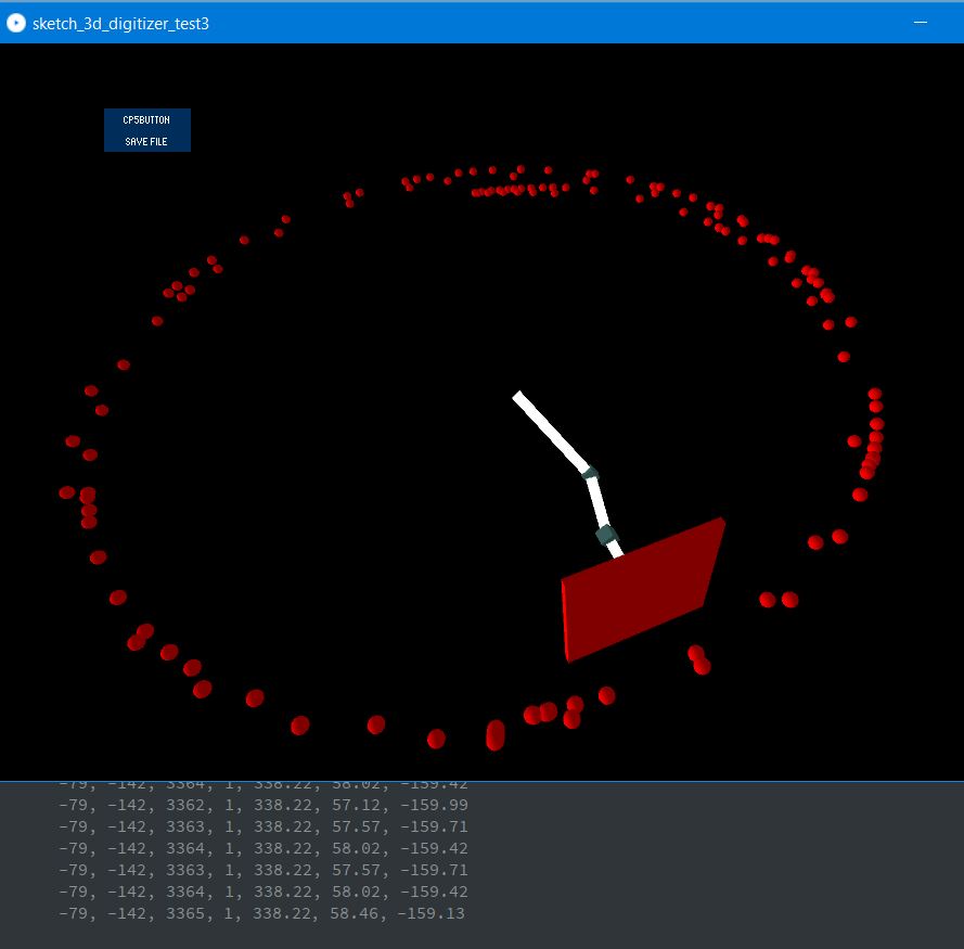
Kept working on it, managed to get the file output to work. It had to do with the button not working as intended. Used a switch case code example found on the controlp5 website and this helped solve the issue.
It outputs a CSV (Comma Seperated Values) file with the point number as well as the tip location in X, Y and Z.
newer version of software for processing (pde file) can be found here
I’m almost done with the minimum viable product for this software.
There’s not too much I need to do except for one main issue, getting the data point and the 3d model to align correctly. This is a bit of an issue, and frankly it’ll be a lot easier once I get the final system built (as that will have the correct arm length, base height, and starting arm positions/angles.)
But I would like to be able to clear points. At least have a clear last point button. Maybe a few other button options. But making progress.
UPDATES:
I managed to add a clear last point button, and it works. Shockingly. Had to jump through some strange hoops (dealing with arrays and erasing data off arrays in Processing isn’t exactly straightforward.)
I’ve made some other changes, mostly fixing mistakes, not so much added features
- I did add a gnomon for X, Y, Z, axis. Made me discover that the arm model is on it’s side, so that explains why I needed to rotate the points by 90 degrees to make them look correct. I’ll fix this later, if I have a chance
- Add the button for removing last point
- Can save data now.
- put helper parts of the code in their own functions and cleaned up code.
- I was having the hardest time getting the ANGLE PRESET functions to work, and then I realized, everything is done with radians, but the angle preset was in degrees. I added the radians() function and that immediately fixed that problem. That took too long to fix.
- When I fixed the above, I also realized that I was sending the wrong presets to the wrong encoders, and fixed this.
new version of software for processing (pde file) can be found here
Encoder board code and notes about programming
And here’s an earlier version of the SAMD21 board encoder code
It now does some of the trig internally, given the length and starting position of the arms and sends X, Y, and Z data along with raw encoder data to the Processing sketch.
I also learned not to use Pin 8, which is a NMI (non-maskable interrupt, you can’t turn it off.) interrupt, and gave me bad readings for my encoders. (the above code probably still has pin 8 and 9 for an encoder. I used pins 9 and 14 instead.) This bug alone took me about an hour to chase down. But it’s not like I can sit there and go “oh yeah, I can live with half the resolution I was expecting from my encoders.”
Once I moved the pins around, and got off of pin 8, my rotary encoders started behaving as they should. I had to make a number of changes to get this board to still send accurate information. I discovered a number of changes I needed to make. (these were less “mistakes”, since I knew most of these were issues, but I did discover a few mistakes while working on this part.)
Changes included:
- Correcting the pinouts so the right encoder was hooked up properly
- Making sure that the correct encoder was hooked up so that it was reading positive in the right direction.
- Making sure each encoder was sending data to the right variable for the trig functions (they weren’t)
- Cleaning up some old code that was no longer necessary
- Changing the Preset angles to be useful and to be attached to correct encoders (this was a mistake I discovered.)
- And actually taking into account the preset angles, adding them to the encoder angles, which I had forgotton to do as well. So even though they were for the wrong encoders, they weren’t being calculated anyways. Also made sure they were being read as Radians, not degrees.
- Fixing all the trig code. There were a number of problems here getting the right data to the right part of the trig formulas. This should be fixed now. (hopefully.)
- have basic LED display when data is being transmitted.
- move small delay function to after updates of variables, hopefully be less likely to promote inaccuracy.
And here’s an older version of the SAMD21 board encoder code created at 6-4-22 10pm
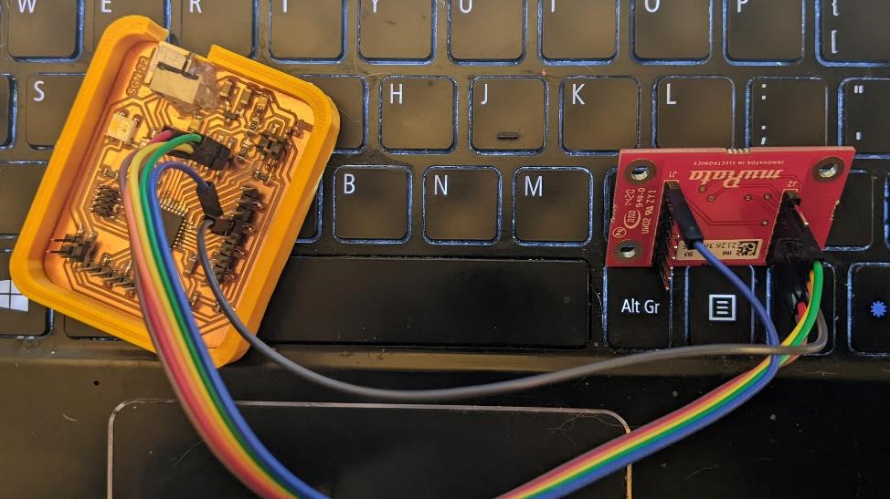
Also gave a quick test to a Murata SCL3300 inclinometer.
I used a Murata SCL3300 test board to help with measuring angles. This was an alternative method to get information for the arm location that I have yet had a chance to work on.
It worked pretty well over SPI. I was using the arduino SCL3300 library written by David Armstrongfor it found here
Right now I’m using a secondary board to read the information off of this. I’d like to be able to hook it up to the mainboard, but right now I’m using the SPI pins for their interrupts. This gives me more reason to re-design the board to pull out the other two “hidden” interrupts.
Sunday 6/5
List of things to do: - create a button housing - create a foot control for button - create a new board, freeing up interrupts (for instance, one interrupt pin is being used for the led, another is the one pin that isn’t connected. I’ll free these up for 2 more interrupt pins for another encoder.) - if I have time (I won’t) create one logic level converter board with 6/8 channels instead of just 2. It will ease cable distribution a bit. - work on final “final” design for base, including start point - work on final “final” design for end effector - clan up all the code and make it more consistent both internally and between arduino and processing.
Latest prototype:
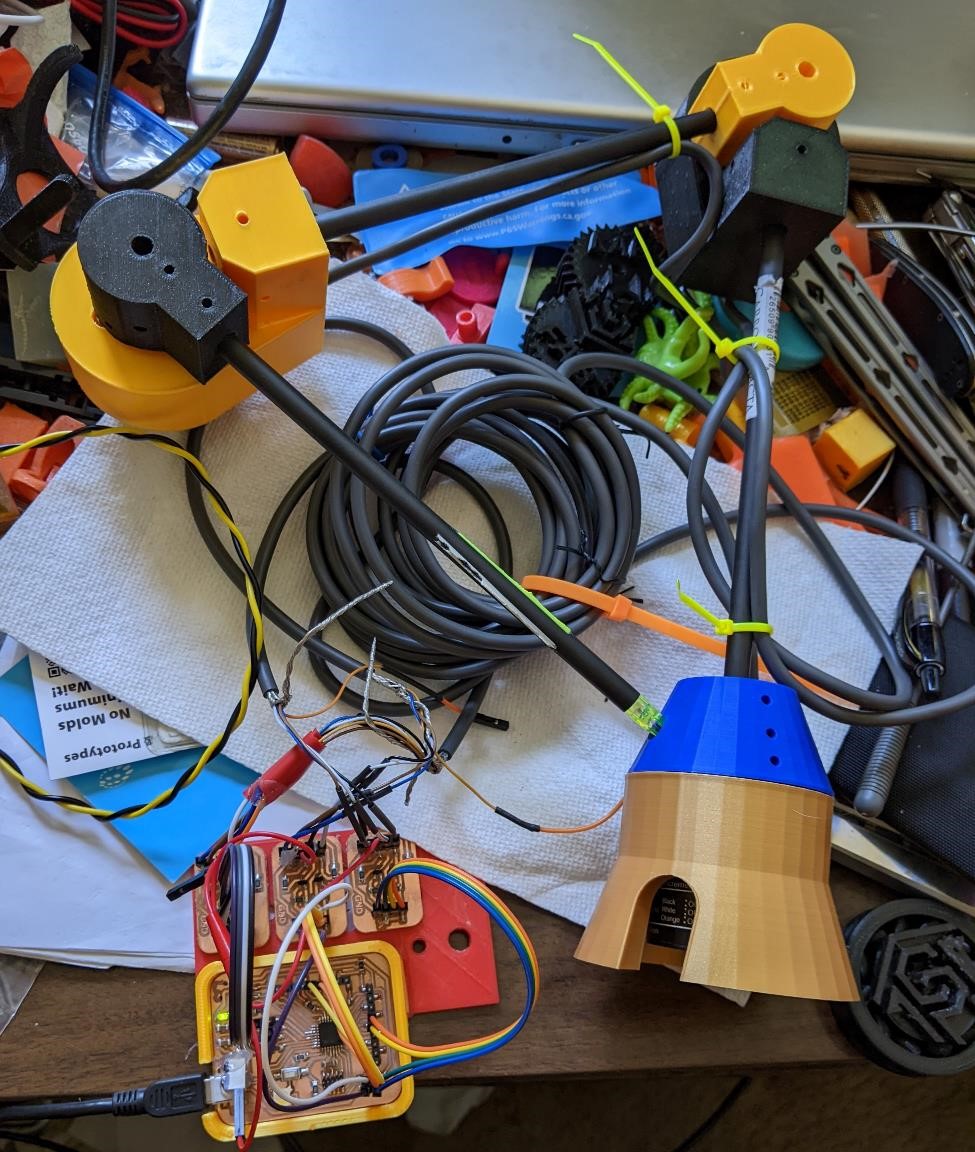
A number of OpenSCAD files I’ve created for this project
Not all of these pertain directly to the arm, but they are all related in one way or another. Either as cases for the boards, pieces to hold some of the “test equipment” I’m using for calibration, or the early test rig I’ve used.
SCL3300 case for 7.65mm arrow shaft
SCL3300 case for 22mm carbon fiber tubing
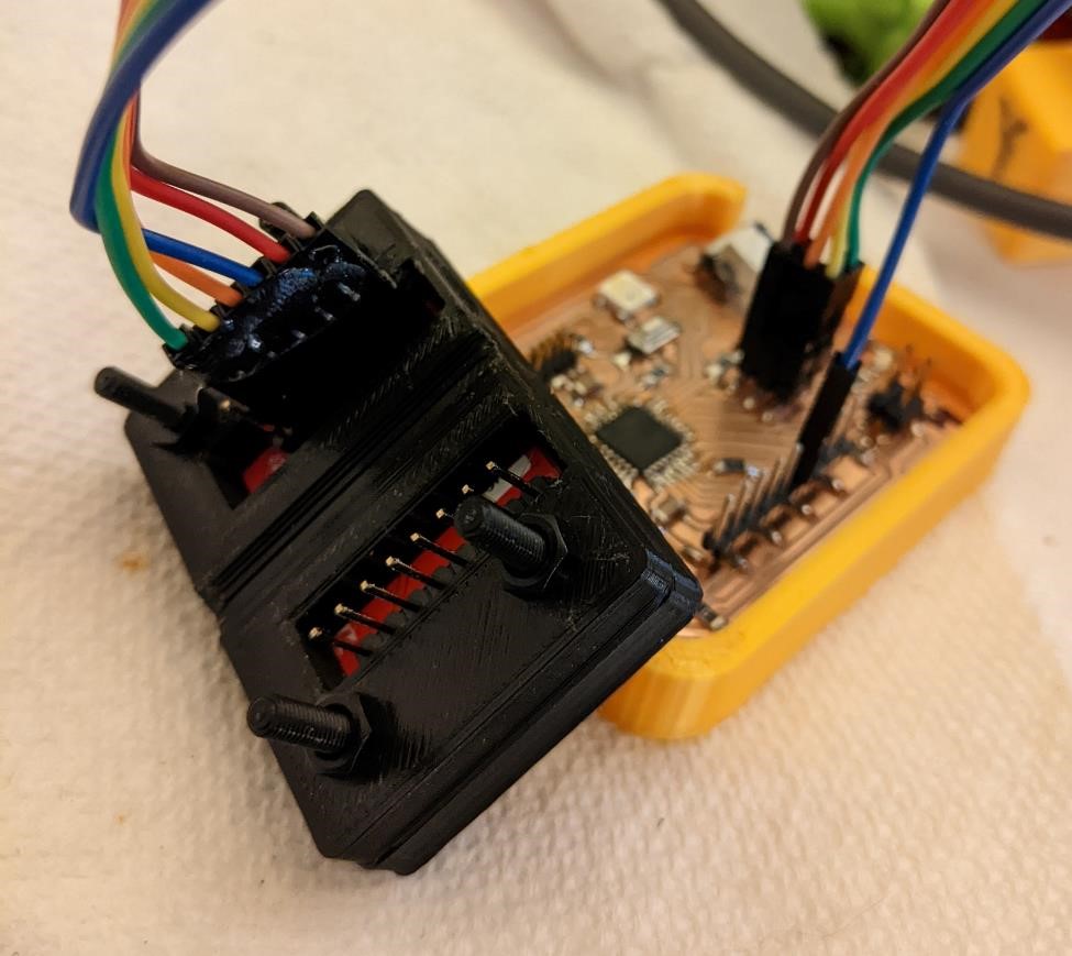
sgn SAMD21 case and logic level converters board
sgn SAMD21 case and logic level converters board v2
3d design and printing
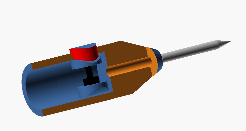
Tonight, I made the probe stylus holder with button.
This button has a small smd tactile switch glued beneath it. I then have two wires connected of course, designed to go through the arm tubing, and then there is a 3d printed plastic piece glued in underneat to support the button. It actually works pretty well. This was just a throw away idea. I’m amazed it worked so well.

Also made a case to fit around the test rig to hold an inclinometer for calibration.
And continued with some refinements of the final design. I thinned out the encoder holders just a smidge (mainly to decrease printing time.)
Next
One thing I want to start working on, though it’s going to be very difficult for me, and I’m sure I won’t finish, is a self-calibration system.
If I give the rough dimensions for the angles and arms, I’d like to use an inclinometer to get more precise angles for each segment of the arm. I’d then like to take this info, input it in the angle presets (that tells the board what the actual angle is, not the estimated/roughly measured angle.)
Then, given a calibration tool, such as a 1-2-3 block (preciously ground block of exactly 1 inch by 2 inches by 3 inches.) or a calibration sphere (a preciously ground sphere of exacting coordinates, such as 0.74999 inches.) I can then touch off on these example parts, and calibrate the tool using these known measurements to get it to be more accurate.