14. Networking
April 27 2022
This week we worked on creating networks.
I’ve made plenty of boards during this class, I’ve certainly got enough to create a network.
I’ve designed a new board (see Week 13) that has pullup resistors for both the input section as well as the i2c interface. But haven’t had the chance to produce it yet, but I’ve the old boards will work for testing.
I want to see if I can create a “network” over the i2c bus. I’m not sure how well it will work, but i’m thinking it’ll be interesting. I’ll have to figure out how to have these boards act like an i2c device, take the data from the rotary encoders and forward it to whatever the final control will be. A number of hurdles to leap. Uf I can just get two boards to talk over i2c, that’ll be a great starting point.
Fake it till you make it - i2c device.
I’m going to have to make a device have a i2c address, and communicate over i2c.
I started with the search engine, and immediately came across this page https://www.electronics-lab.com/build-i2c-sensor/ which uses an Attiny85 with a light sensor acting as an i2c device.
And I came across this from another FabAcademy link: https://www.instructables.com/Arduino-I2C-and-Multiple-Slaves/
Thankfully, the Arduino IDE has a lot of support just for this. It uses the Wire.h library.
This library takes care of much of the heavy lifting, and very much like the Serial library, makes it fairly easy to communicate over i2c. For this, I’m using the tinyMegacore Wire library (which is supposed to be a direct close for Attiny processors.)
I’ll be giving one device an i2c address, treating it as receiver, and one device will be treated as a transmitter. They’ll communicate over the i2c ports (SDA and SCL) and hopefully one will received the information transmitted by the other.
Notes about i2c
i2c devices need pullup resistors. I used 10k on my boards, just because… (probably too much, but whatever.)
i2c is not like serial, where you cross the lines (RX connects to TX and vice versa for the other two wires). With i2c, don’t cross the streams. SDA goes to SDA. SCL goes to SCL.
There needs to be one master and one slave (or now-called secondary). The master tells the secondary devices what to do. You’ve got to have a master device somewhere in the communication system or you will not get information.
The i2c have addresses. These are hexadecimal and might appear as something like “0x41” or “0x13”, “0x2E”, etc.
Devices usually come from the factory with a fixed address. Some devices may have an alternative address so that they do not collide with another device, but you’ll usually have to do something to make this work (for instance, connecting a pin on the device to GND or VCC.) Some can be changed with a simple tweak of code (on the device).
Here’s a list of addresses for typical sensors and their i2c addresses from Adafruit: https://learn.adafruit.com/i2c-addresses/the-list. And there are ways to use multiples of the same sensors, though you have to be research this to make sure.
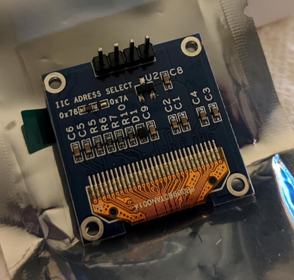
Some devices you can change their i2c address, in the following case by moving a resistor from one pad to another.
(And see Week 12 for more information on finding out your devices i2c address.)
Because I’m using the Attiny412 and megaTinycore, this document is specifically about the attiny412 and i2c (“wire” in arduino): https://github.com/SpenceKonde/megaTinyCore/blob/master/megaavr/libraries/Wire/README.md (this is not the only i2c library, but it’s one that is very often used in Arduino code.)
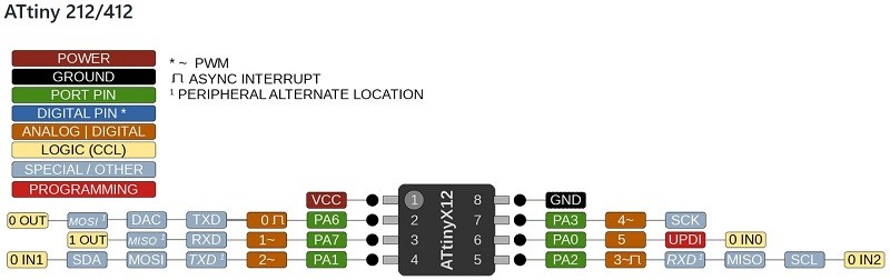
The 8 pin tiny uses PA2 (SCL), PA1 (SDA).
And the typical attiny412 reference:
Not Enough Memory
When I started on this, I ran into a simple, but unsolveable issue. There is not enough memory in the Attin412 to run the Wire library in some instances. And I was unable to get the Wire library and Neopixel library to work together, also because of a limited amount of memory.
The biggest issue is that if I used code, such as from the above instructables link, it would fail to compile. However, if I used code from the megaTinycore example library, it worked. While the code was different, on the face it seemed like it was doing the same thing. Of course, I’m no programming expert (or even novice) so I understand there are a lot of things that could be going on under the hood causing this issue, but because of these small subtle differences, it made it hard for me to get the code to compile if I made changes.
The Code is small enough that I’m going to include it below as an addendum, see the end of this page.
![]()
UPDATE - SAMD11
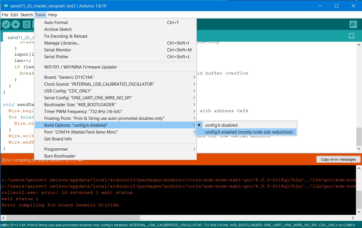
Found away to help with this on the SAMD11 at least. It won’t solve all the issues, and of course it doesn’t benefit the attiny412 at all, but I’ve gotten a SAMD11 with both Adafruit_neopixel.h and Wire.H to compile. The trick is to go under “Tools” -> “Build Options” -> and select “config.h enabled.” This helps shrink the code (generally about 5%, which is just barely enough.)
The below code in the image doesn’t compile with config.h disabled (it said it overflowed flash by 176 bytes of max 12288 bytes.), but enable it and the code compiles. (at 95%, or 11792 bytes)
Wiring.
I’ve got to be careful not to flip the 5v and GND wires when making these connections. I’m usually pretty good about adding notations to my boards, but I’m not perfect. I also need to make sure that I’m switching between SAMD11 and Attiny412, I’m powering them both with 3.3v.
The other thing is that I need to make sure to connect SDA/SCL correctly, though it’ll be quick to fix this, and won’t burn anything out.
Finally, since I’m also using serial communications to collect and see data, I have to make sure that I connect the serial cables correctly as well. And this means to remember to connect RX from one board to TX on the other, and the same with the other pair of TX/RX.
Basically it’s a lot of crappy little cables going everywhere, and it becomes a rats nest very quickly.
Need better cables - Did it
Because I would like to have more than 2 of these boards connected, I’m going to want to make some custom cables that allow for keeping these all daisy chained. Won’t be tooo difficult, just have to make sure that I keep the board designs stable, don’t flip anything (like 5v and GND, not that I’ve done that before…) and have the right physical cable connections (like a 4 pin IDC. I’ve come to hate Dupont cables, the cheap ones become garbage after just a few uses and have intermittent connections, making it a nightmare to debug this stuff. “Is it my code or do I just have a bad wiring connection?”)
A lot of writing for a cable, but it’s something I don’t want to overlook. I donn’t want to have more issues because of bad wiring, just bad design, code, boards, and the normal things I mess up.
Update: Made some cables using IDC connectors.
I took some 8 conductor ribbon cable, sliced it in half and crimped on the 4 pin IDC connectors we had. I used a vice to crimp these, but a) vises area awesome. b) vices are fun. c) it works really well.
One thing to note is that these connectors have offset “teeth” that grab each strand of the wire. You need to take note of which is which, and the fact that these connectors are keyed (but your male header cables may not be, so be careful!). So keep track of which wire is connected to which tooth of the cable connector.
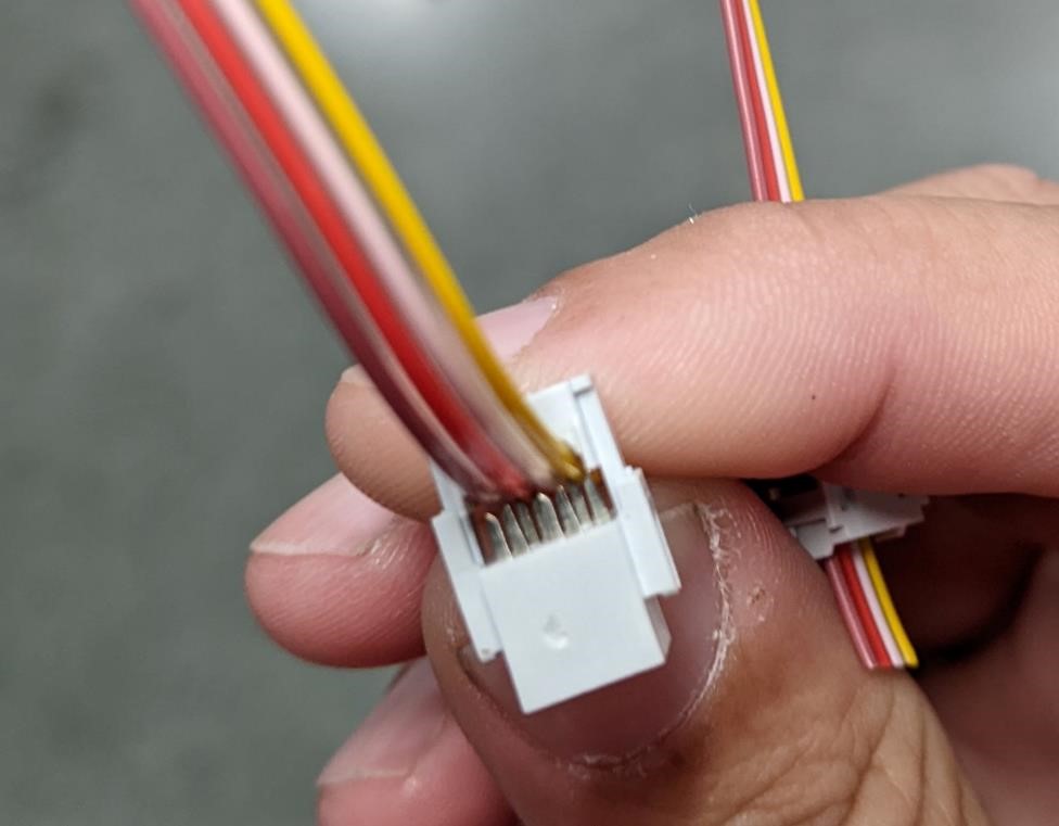
For this part, they were all connecting to i2c (so don’t have to worry about flipping cables like with serial (rx and tx)). And they will provide 5v and GND to each succeeding (secding) board.
These things really made connecting boards way easier. I wish I had made these cables much earlier. It also makes me wish I had planned out every board to use IDC connectors (especially the keying). I’ll start designing using these going forward. They do have constraints (height and footprint on board being biggest).
Reading Serial Data
I’m having data transmitted over i2c, but I have no way of seeing the i2c network currently. I’ll be hooking up a programmer as a serial device (that will read and transmit serial data, as well as power) that I can then see on the Arduino Serial Monitor.
As always, make sure that your programmer (that’s been programmed to be a serial reader, using 8N1, is set to the same baudrate as the program itself. If you use Adam Harris programmer serial reader program, you’ll need to change the serial portion to the above 8N1, and it uses 57600 baudrate.)
The Attiny412 is capable of having one serial port, but it can use two different sets of pins. For this Attiny412 board, I’ve been using physical pins 2 and 3 as my input for sensors (and I leave physical pins 5 and 6 available for the i2c network.) And this is why often, when setting up the Serial communications, you’ll see “Serial.swap(1)” in the code. This is telling the attiny412 which set of pins to use for serial communications. But of course, this secondary set is the same two pins used for i2c communication.
For this setup, I’m using the normal (physical pins 2 and 3) pins for the Serial communications and using physical pins 5 and 6 for i2c. Yes, this is a bit confusing. It took me too long to figure out the “Serial.swap(1)” trick.
And of course, using an Attiny412 with an i2c hookup, serial, and leaving open the UPDI pin for programming, uses up every single pin except for 1.
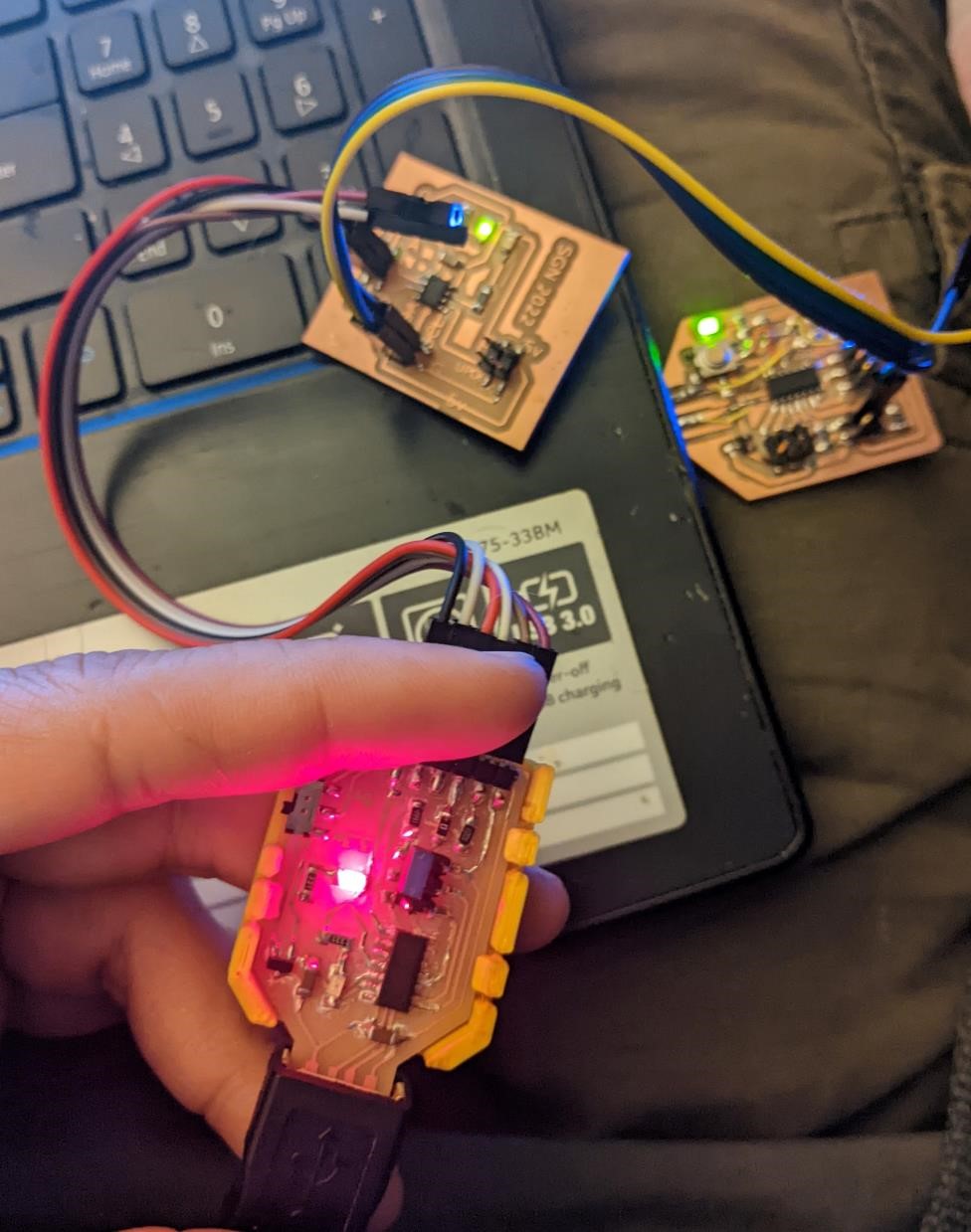
Creating an i2c network - Success!
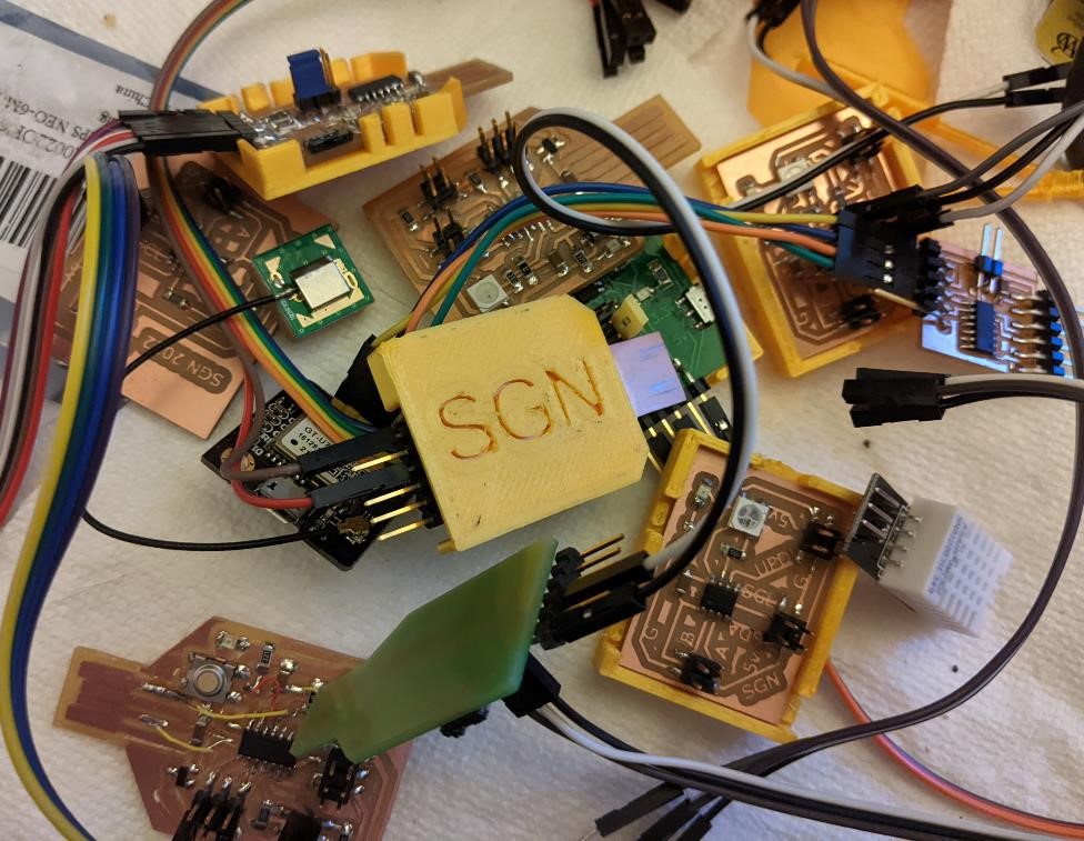
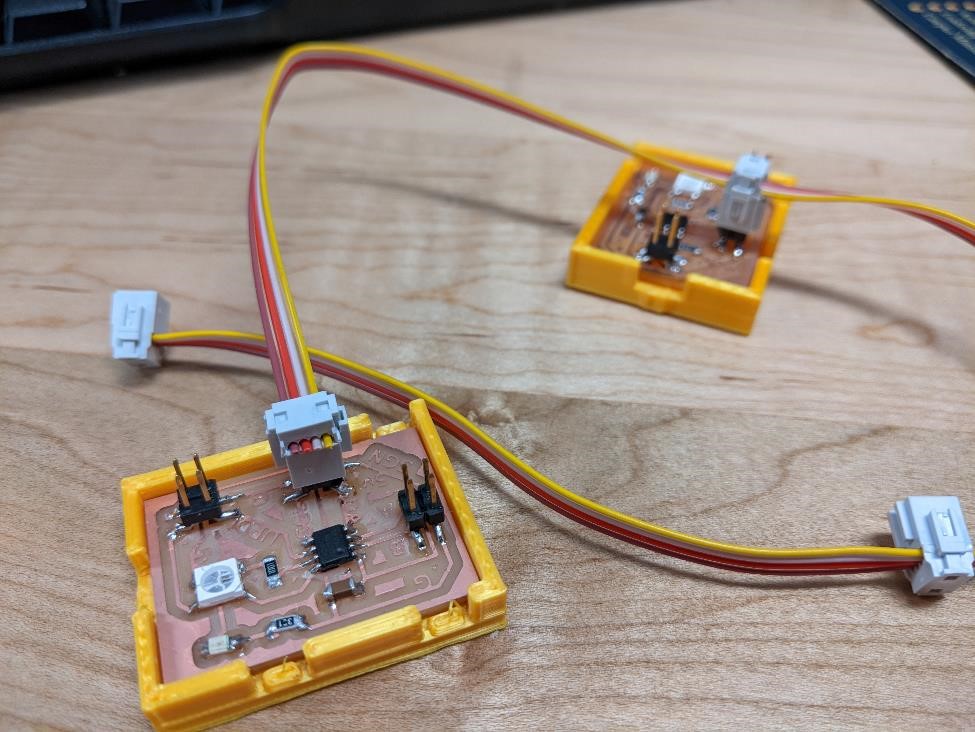
I was able to create an i2c network.
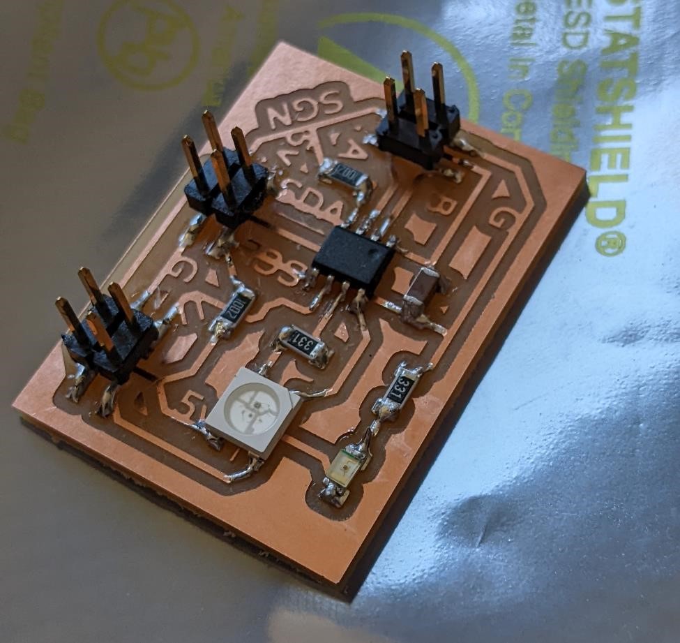
I used two attiny412 boards (one was an older version, which did not have SDA/SCL pull up resistors, but as I only need them on one device, this worked.) (board v1 on the left, v3 on the right. Difference between these is replacement of led with neopixel and addition of i2c pullup resistors.)
These two boards were programmed with a “master write” and a “slave read” program respectively.
The i2c address given to the slave board was “0x54”
I’m having some issues with getting the LED to turn off, I think it’s partly because for testing, I’m just sending the “testing” message every 100 microseconds, and my code for turning the LED off “digitalWrite(led, LOW);” is in the wrong place. But I think I can fix this.
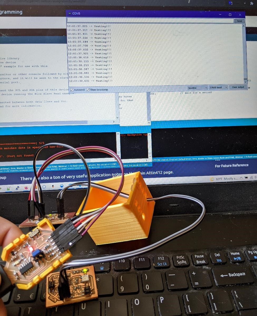
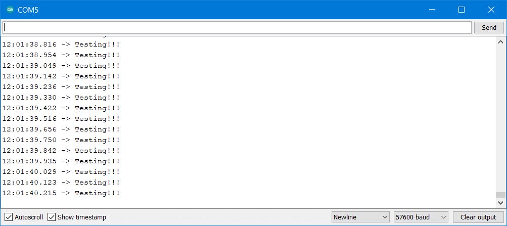
However, on the Serial Monitor, I’m receiving the data from the master, via the secondary, and out through the serial port of the board into the Arduino IDE serial monitor.
Master Code Network Test
I heavily modified the code from the megaTinycore Wire library examples. First written by MX682X
The code for the master is simply sending a “test” signal. It’s about as simple as it could get.
#include <Wire.h>                // This is the Arduino i2c library,
                                // this "#include" tells the program to use it.

void setup() {
    Wire.begin();                       // initialize Wire Library (handles i2c), this library
                                        // does all the heavy lifting for us.
}

void loop() {                       // Main part of program, but it just calls a function
    sendDataWire();                 // call a function to send the data over I2C
}

void sendDataWire() {
  Wire.beginTransmission(0x54);     // prepare transmission to slave with address 0x54
  Wire.write("Testing!!!");         // Write this data ("testing!") to the wire buffer
  Wire.write("\r\n");               // add new line and carriage return for the Serial monitor
  Wire.endTransmission();           // finish transmission
  delay(300);                       // wait a third of a second, go to main loop.
}
Secondary Code Network Test
The slave code is heavily modified from the example library as well (first written by MX682X), and added a “blink” code to blink the led when an i2c message is received.
Note that I am not using the “Serial.swap(1) I would normally use. In this case, the serial pins are physical pins 2 (TX) and 3 (RX).
#include <Wire.h>

int led = 4;  //simple sgn attiny412 v1 led pin

#define MySerial Serial           // This is using the "serial" library (built in)
                                  // and gives it a name, "MySerial." We'll call "MySerial"

void setup() {                     // This prepares the program, only runs once.
  pinMode(led, OUTPUT);             // Prepares the pin of chip for output, names it "led"
  Wire.begin(0x54);                 // join i2c bus with address 0x54
  Wire.onReceive(receiveDataWire);  // give the Wire library the name of the function
                                    // that will be called on a master write event.
                                    // When the chip receives i2c data, it sends it to
                                    // the "receiveDataWire" function below.
  MySerial.begin(57600);            // Opens up Serial port at 57600 baud for Serial Monitor
}

void loop() {                      // Main part of program, but it doesn't do anything!
  delay(100);                      // well, it delays...
                                   // because everything really happens in setup above.
}

// function that executes whenever data is received from master
// this function is registered as an event, see setup()

void receiveDataWire(int16_t numBytes) {      // the Wire library tells us how many bytes
  for (uint8_t i = 0; i < numBytes; i++) {    // were received so we can for loop for that
    char c = Wire.read();                     // amount and read the received data
    MySerial.write(c);                         // to print it to the Serial Monitor
    digitalWrite(led, HIGH);                  // turn on LED
  }
  digitalWrite(led, LOW);                      // out of for loop, turn off led.
}
Blink over i2c network
Next I wanted to make the LED blink, using the i2c network. I’ll have the master unit send a byte of the LED state as either on or off. The slave unit will then turn it’s LED on or off based on the data received. It’ll also output a message over the serial port stating what the state of the LED is. For this test case, I simply had the master board cycle through LED on and off every half second for testing purposes.
And amazingly, it worked.
And the serial monitor outputting the commands received over i2c.
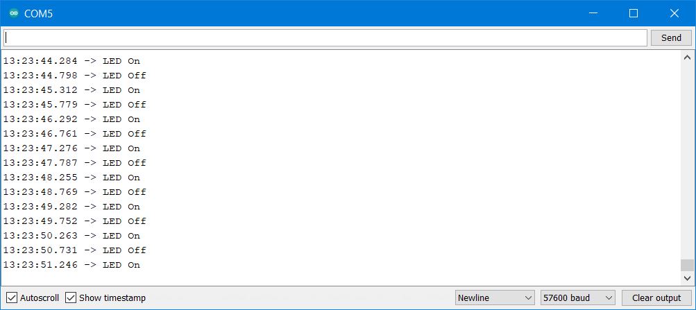
Here’s a short video, showing two attiny412 boards (one master, one slave), a programming board providing the power and serial interface, and the arduino ide serial monitor showing the activity being reported by the secondary board.
Master LED Blink Test i2c Code
I want to note in the below code that the “led_state” isn’t actually telling the other board to turn the led on or off, it’s just simply sending a “1” or “0.” The other board will determine what to do with that data. This “led_state” variable is really just a mnemonic so that you, the programmer, have an idea of what the variable will be used for on the other end of the connection.
#include <Wire.h>

byte led_state;                      // a variable, storing the led "on" or "off"

void setup() {
  Wire.begin();                       // initialize i2c system
}

void loop() {
  led_state = 1;                  // value of "1" will be set.
  sendDataWire();                 // call the function to send the data ("1") over I2C
  delay(500);                     // wait half a second
  led_state = 0;                  // change value of data to "0"
  sendDataWire();                 // fall the function to send data.
  delay(500);
}

void sendDataWire() {              // This is where it actually uses the i2c system to send data
  Wire.beginTransmission(0x54);    // prepare transmission to slave with address 0x54
  Wire.write(led_state);           // Write the received data to the bus buffer
  //Wire.write("\r\n");               // add new line and carriage return for the Serial monitor
  Wire.endTransmission();           // finish transmission
}
Secondary LED Blink i2c Code
#include <Wire.h>                 // This does a lot. Handles hard work of i2c connection.

int led = 4;                      // the pin that the LED is connected too.

#define MySerial Serial           // This is using the "serial" library (built in)
                                  // and gives it a name, "MySerial." We'll call "MySerial"

void setup() {
  pinMode(led, OUTPUT);             // turns the led pin to output, to turn led on/off
  Wire.begin(0x54);                 // join i2c bus with address 0x54
  Wire.onReceive(receiveDataWire);  // give the Wire library the name of the function
                                    // that will be called on a master write event
  MySerial.begin(57600);
}

void loop() {
  delay(100);                   // Doesn't do anything, main action starts in setup
}


void receiveDataWire(int16_t numBytes) {      // receive data over i2c in 16bit int
    byte led_state = Wire.read();             // get data from i2c, variable "led_state"
    if ( led_state == 1) {                    // if it's 1, do the below:
       digitalWrite(led, HIGH);               // Turn the pin for the led on High (led on)
       MySerial.write("LED On");              // send data out over serial saying "Led on"
       MySerial.write("\r\n");                // Writes a newline to serial monitor
    }
    else {                                    //but if it's not a 1...
       digitalWrite(led, LOW);                // send a low to the led pin, turn led off.
       MySerial.write("LED Off");             // and send this text to serial monitor
       MySerial.write("\r\n");
    }
}
What are all of these “int”, “uint8” and “int16_t” things? See here: https://www.nongnu.org/avr-libc/user-manual/group__avr__stdint.html
And now a SAMD11 board
And after that worked (yay), I then used a SAMD11 board I have built to send commands (via the USB serial connection of the SAMD11) to turn an LED on and OFF on an attiny412 board. I powered the attiny412 via a programming board at 3.3v (or directly connected to attiny412 board since it will run off 3.3v), so I didn’t have to worry about power and logic mismatches.
But this worked. (the above secondary code was kept the same for the attiny412 board.)
I could turn the LED on by sending a “1” via the Arduino serial monitor, and turned the led off by sending a “0.” It’s a very complicated, very computationally powerful, very low watt light switch. My parents are very proud.
#include <Wire.h>                  // include the i2c library

String readString;         // this is a variable for text
byte I2C_OnOff;

#define MySerial SerialUSB   // Our serial port is now over USB
                            // This is a built in component.

void setup() {
  Wire.begin();                       // initialize i2c system
  MySerial.begin(0);                  // turn on USB serial system
}

void loop() {
   if (MySerial.available() > 0) {    // if the serial is on...

    delay(2);                       // wait a split second
        char c = MySerial.read();   // get the data from serial port.
    readString += c;                // the data is named "readString"
  if (readString == "1")            // if data says "1"..
  {
    I2C_OnOff = 1;                    // turn on the LED
  }
  else if (readString == "0")        // if the data is a zero...
  {
    I2C_OnOff = 0;                   // turn off led
  }
  if (readString.length() > 0)       // if it's received any data...
  {
    MySerial.println(readString);    // print that data to ther serial usb port.
    readString = "";                 // erase the data, to prepare for next data input
  }
  Wire.beginTransmission(0x54);   // send the data to i2c address 0x54
  Wire.write(I2C_OnOff);          // write data to i2c of variable "I2C_OnOff"
  Wire.endTransmission();         //End of Transmission
  }
}
Multiple boards.
New Attiny-whatever board
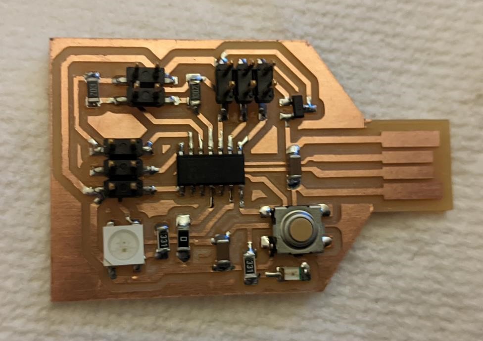
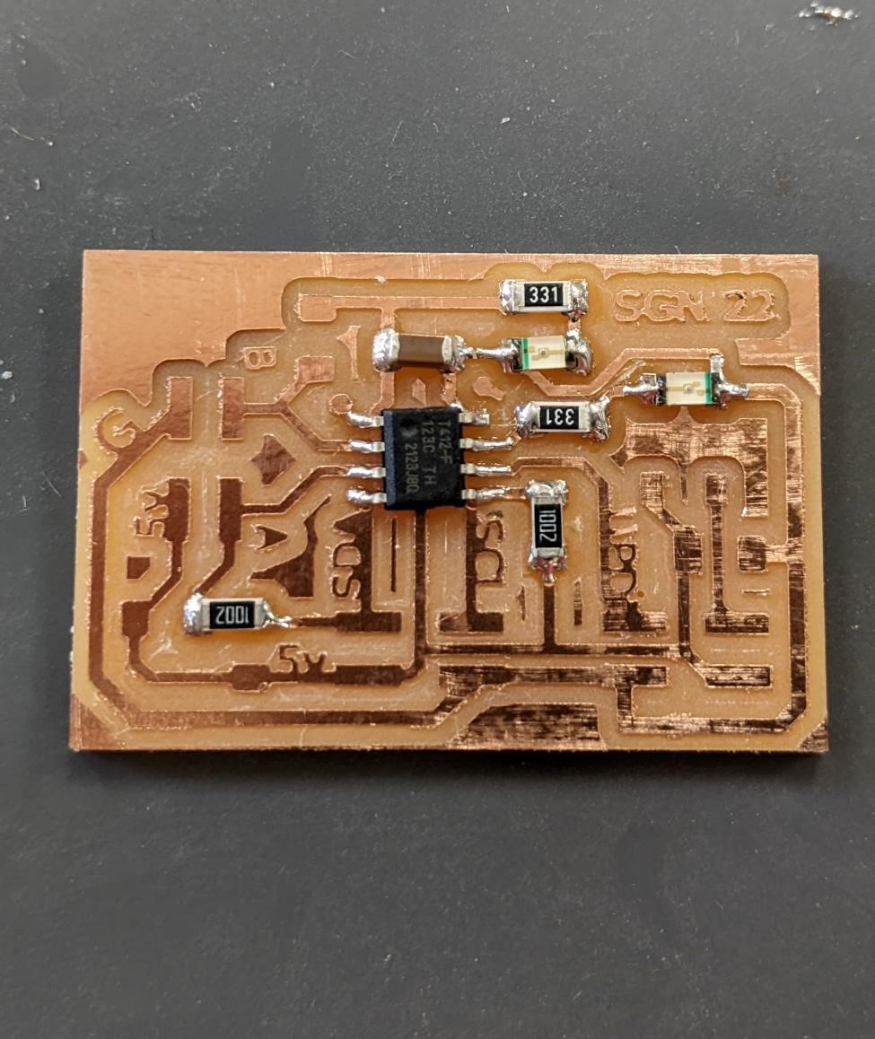
I kept changing my attiny412 based board. I added two 1k pullup resistors to it, as well as the ability to use a normal smd led or a neopixel (I really didn’t do anything for this, it’s inherent in the neopixel design)
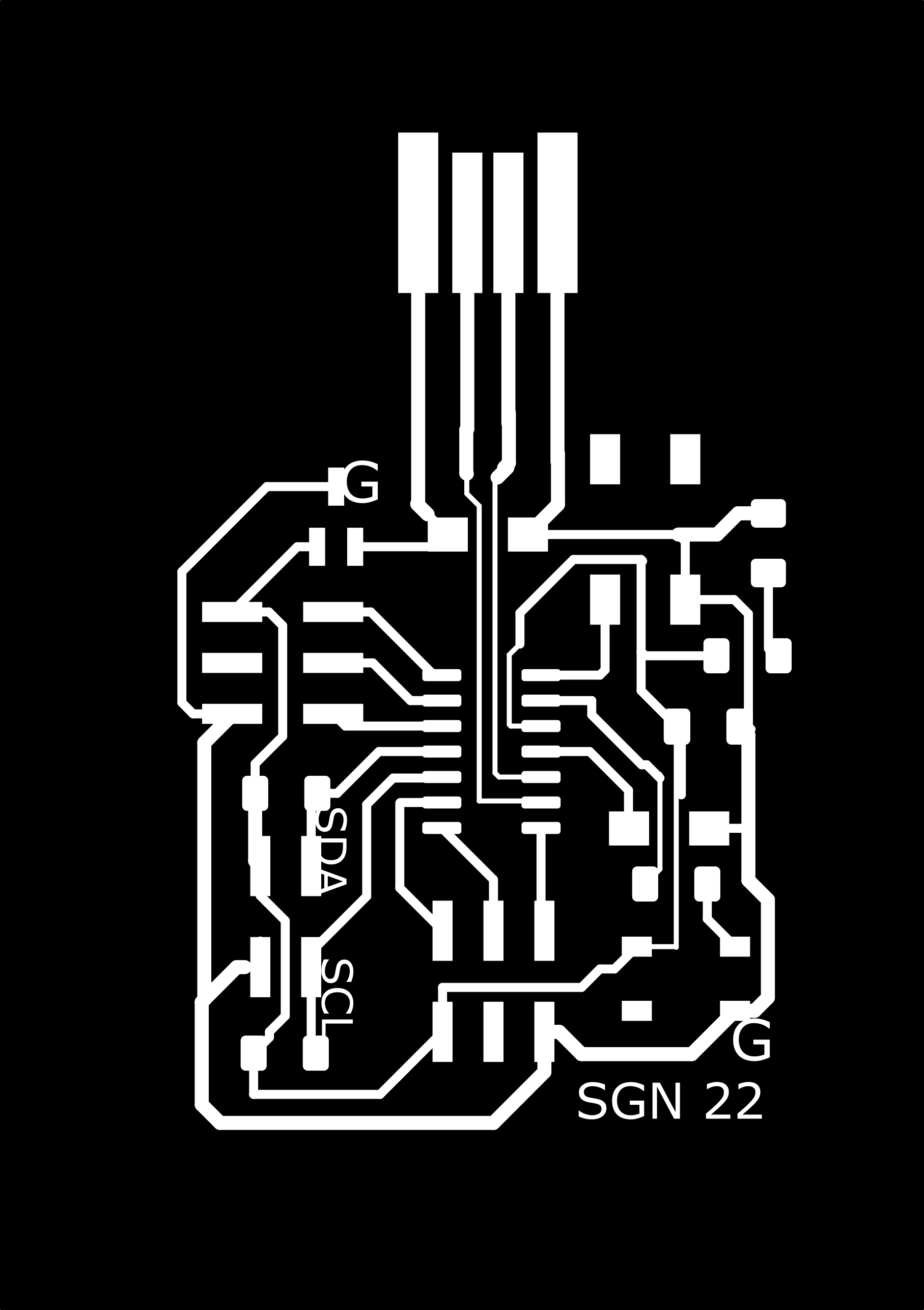
There is a problem with this design that I need to fix. One of the board traces get’s too close to another, and as such, using a 1/64th endmill, and using Mod’s, it will not cut between these two traces, leaving them connected and that will be an issue. For these two prototypes, I took a exacto blade and sliced between the two parts, cutting the copper. With this modification, the boards worked fine for the basic blink and i2c network tests.
![]()
![]()
(Updated: I had a small mistake in the above board. One of the traces was too close to another and so Mod’s wouldn’t mill a slot between the two. I’ve now updated the board so this should no longer be a problem.)
And here’s version that’s in the process of being stuffed and soldered:
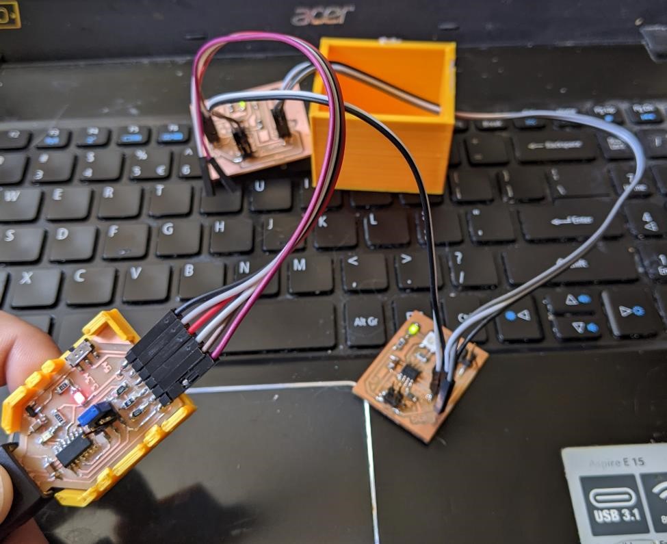
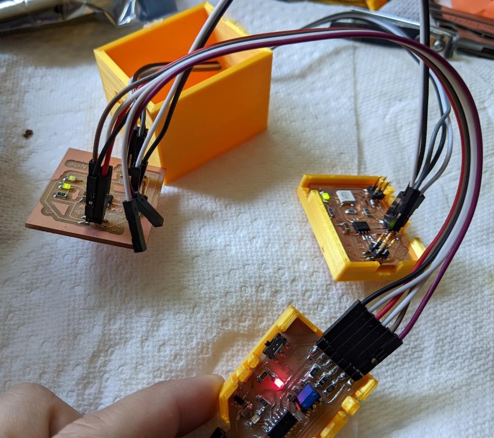
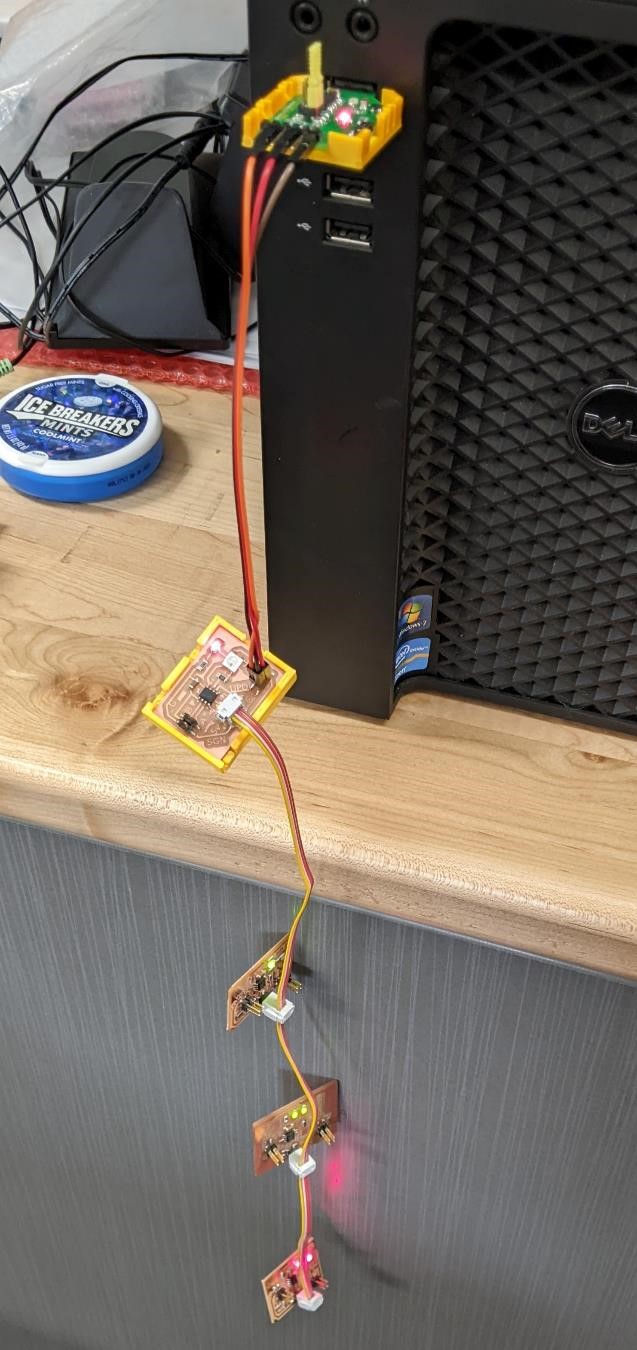
I hooked up two of these new boards with the older versions of the board.
I’ve changed the above code, and I simply copy and pasted the functions of the master for multiple boards (I’ll be adding that program here shortly, I left it at school.)
I also had to change the addresses of the subsequent boards. I used the same slave code for each, but simply incremented the address by 1. Board one was “0x54”, board two was “0x55”, board three was “0x56.”
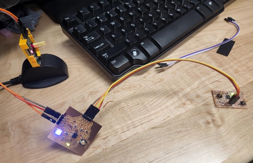
And here’s that image of my network. THe programmer is providing power from the USB. I have a master board that is then sending out commands to the slave boards to turn on and off their led’s.
What’s next
Next I need to get data from these slave boards and send it to the master board. As it is now, it’s a one way communication. I need to have the slaves send data to the master board. I’m planning on hooking up buttons (something simple) and have this data sent to the boards.
I’m probably going to have to move away from the attiny412 and SAMD11 boards. They just don’t have enough memory to accept the normal arduino libraries, and I’m not going to re-write these libraries for these boards. I really wanted to use the neopixels as the output, but again, not enough memory.
I’m going to start looking into the attiny1614 and SAMD21, as well as the granddaddy 328p for replacements.
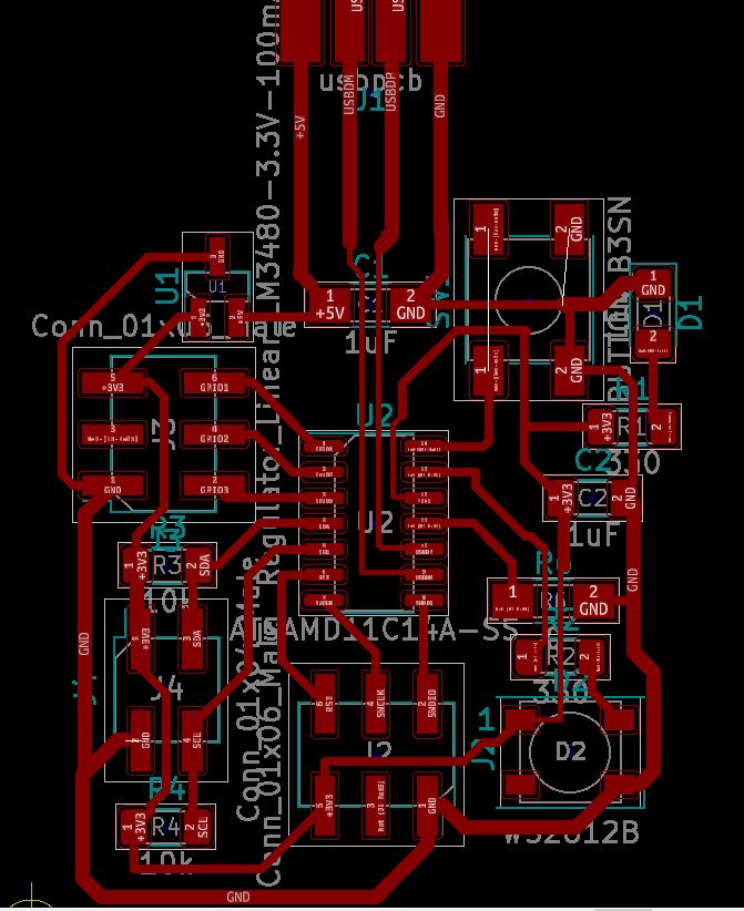
But I did make slight changes to the SAMD11 board. I flipped the power and gnd pins that are connected to i2c simply so that I could use the same above 4 conductor idc cables to transfer power and i2c between the samd11 boards and the attiny boards. (I just changed the lines in Inkscape, because I didn’t have the kicad files with me when I wanted to make these changes.) Updated: I’ve now made the changes to the actual kicad files, updated the PNG’s (the inkscape ones only saved at 100dpi, so they were useless anyways) and I’ve updated the schematic to reflect the change as well.

And the new schematic to go along with it:
Group Project
Cori and I made two very similiar attiny412 based boards, and we networked them using i2c.
You can see more about this on the Week 14 Group Page
We had Cori’s board act as a master (down with the patriarchy!) and Garrett’s act as a slave. Cori’s board then communicated to Garrett’s and had his board do what she told it to do. Very demeaning.
I learned that in the future, if you’re building boards for networking, you need to make sure that the wiring connections are similiar enough to make hooking them up easy (for two boards, it doesn’t matter much, but as you add more boards and sensors, this becomes more important.)
But it worked, and one board told another board to turn it’s led on an off.
Files
As almost always, see above for the code used for this project. Board files can be found in other week’s assignments.
Resources and References
I noticed in the past week, Hackaday has had some interesting articles on i2c. I’ve included them here as references: https://hackaday.com/2022/05/04/the-connector-zoo-i2c-ecosystems/ and https://hackaday.com/2022/05/02/i2c-tap-helps-assign-blame-for-sda-conflicts/ and this older i2c reference from hackaday https://hackaday.com/2016/07/19/what-could-go-wrong-i2c-edition/
https://www.electronics-lab.com/build-i2c-sensor/
And Information about the TinyWireS and TinyWireM libraries https://playground.arduino.cc/Code/USIi2c/
And of course, there’s always someone who’s done this before in FabAcademy: https://fabacademy.org/2021/labs/waag/students/douwe-schmidt/assignments/week13/
https://fabacademy.org/2020/labs/oulu/students/xinhui-hu/Week14_Interface_and_Application.html
http://fab.cba.mit.edu/classes/MAS.863/CBA/people/raechel/week6.html
http://www.technoblogy.com/show?2QYB
Lack of Memory Issues and different code
I don’t know enough to determine what the key difference between these two programs are, and why one would compile and the other would not.
Code from Instructables, WOULD NOT compile:
#include <Wire.h>
String readString;
byte I2C_OnOff;
void setup()
{
  Wire.begin();
  Serial.begin(9600);
  Serial.println("Type On to turn on the LED and Off to shut it down!");
}
void loop()
{
  while (Serial.available())
  {
    delay(2);
    char c = Serial.read();
    readString += c;
  }
  if (readString == "BlueOn" or readString == "BLUEON" or readString == "blueon")
  {
    I2C_OnOff = 1;
  }
  else if (readString == "BlueOff" or readString == "BLUEOFF" or readString == "blueoff")
  {
    I2C_OnOff = 0;
  }
  if (readString.length() > 0)
  {
    Serial.println(readString);
    readString = "";
  }
  Wire.beginTransmission(1);
  Wire.write(I2C_OnOff);
  Wire.endTransmission();
}
Code from the megaTinycore examples, which WOULD compile:
/* Wire Master Write
 * by MX682X
 *
 * Demonstrates use of the New Wire library
 * Writes data to an I2C/TWI slave device
 * Refer to the "Wire Slave Read" example for use with this
 *
 * Enter any data using serial monitor or other console followed by either or
 * both of the line ending characters, and it will be sent to the slave, which
 * should print it out on it's serial port.
 *
 * To use this, you need to connect the SCL and SDA pins of this device to the
 * SCL and SDA pins of a second device running the Wire Slave Read example.
 *
 * Pullup resistors must be connected between both data lines and Vcc.
 * See the Wire library README.md for more information.
 */

#include <Wire.h>

char input[32];
int8_t len = 0;

#define MySerial Serial               // The serial port connected to the to the computer.

void setup() {
  Wire.begin();                       // initialize master
  // MySerial.swap(1);                 // Remember to swap serial pins if you need to do that with your connections.
  MySerial.begin(115200);             // Use 115200 baud - this is the 2020's, and these are modern AVRs.
}

void loop() {
  if (MySerial.available() > 0) {      // as soon as the first byte is received on Serial
    readFromSerial();                 // read the data from the Serial interface
    if (len > 0) {                    // after the while-loop, if there was useful data,
      sendDataWire();                 // send the data over I2C
    }
    len = 0;                          // since the data was sent, the position is 0 again
  }
}

void readFromSerial() {
  while (true) {                      // in an endless while-loop
    while (MySerial.available() == 0);// means we've taken all the bytes in, and are still waiting for a cr/lf.
    char c = MySerial.read();         // read the next char, now that there's one available.
    if (c == '\n' || c == '\r') {     // until a new line or carriage return is found
      break;                          // if so, break the endless while-loop
    }                                 // otherwise
    input[len] = c;                   // save the char
    len++;                            // increment the  position
    if (len > 30) {                   // if there was too much data
      break;                          // break the while-loop to avoid buffer overflow
    }
  }
}

void sendDataWire() {
  Wire.beginTransmission(0x54);     // prepare transmission to slave with address 0x54
  for (uint8_t i = 0; i < len; i++) {
    Wire.write(input[i]);           // Write the received data to the bus buffer
  }
  Wire.write("\r\n");               // add new line and carriage return for the Serial monitor
  Wire.endTransmission();           // finish transmission
}