Work log - Week 1 - January 26, 2022
This is just a way to keep a record of what I’m doing during FabAcademy Spring 2022.
1/23
Starting point - Project Idea
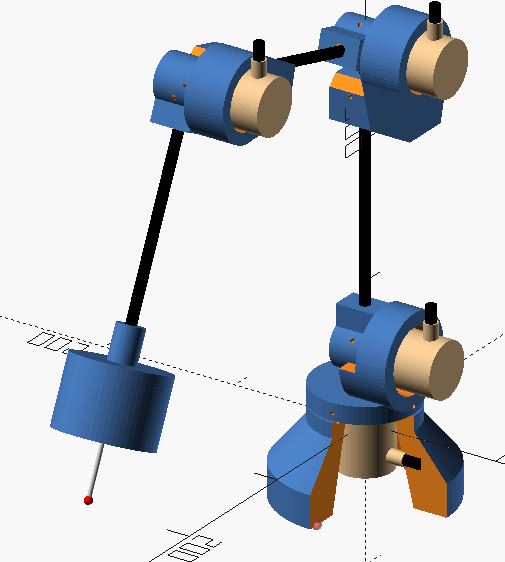
- Started a rough sketch for digitizer arm using OpenSCAD. This is just a rough outline, to help with design.
-
Started looking into rotary encoders, came across these sites:
1/24
- Continued with digitizer arm sketch, started on probe.
- Started looking into electronics necessary to get multiple encoders to talk to Arduino.
-
Came across the following resources:
1/27
- Wrote project document. Realized I’m in over my head.
- Built website.
- Broke VScode and git. I have no idea what happened, Though I think it had something to do with cloning two repo’s from HTTPS.
1/28
- Continued with research, design, and documentation.
Prior Art
-
Looked for prior art. Discovered:
- https://fablab.ruc.dk/diy-digitizer/
-
http://blog.dzl.dk/2018/08/21/3d-digitizer/
- I believe this is just an update on the fab lab project. Which includes a turn table.
- Excellent resource on how he found polar coordinates.
- https://github.com/dzlonline/3D_digitizer2
-
https://www.thingiverse.com/thing:2882172
- I like the way that he added the weight, as well as the large ball bearing around the top of the base. I had previously thought of the bearing, but the weight is a good idea.
-
https://forum.makerforums.info/t/ccm-digitizing-arm-5-axis-faro-arm/78981
- github: https://github.com/BL-Shopwork/CCM-Arm
-
And a whole bunch of other stuff. See Final Project for more…
1/29
Rotary Encoder Research
Spent a lot of time looking into how to connect rotary encoders to receive signals. Found that one Arduino Uno would not be sufficient due to lack of interrupt pins. An Attiny85 for each rotary encoder may be the correct way of doing this. But these will still need to be connected to arduino/computer. I’m continuing to research and learn a lot more about interrupts and quadrature encoders than I ever thought I’d know. See References for more information.
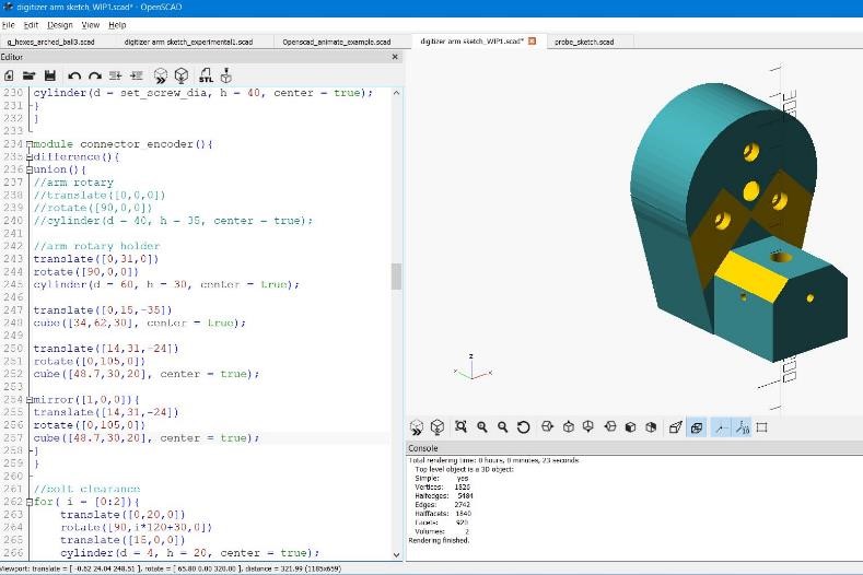
- Continued the design of the digitizing arm. Spent a lot of time modelling and tweaking design in OpenSCAD. Taking the rough sketch and turning it into an actual physical object takes a lot of time. Making a number of small design changes as I get accurate dimensions of parts. Will also have to make a number of test pieces to check clearances/tolerances, etc.
1/30
- Continued research rotary encoders, connecting and programming. Learned about interrupts. Last time I dealt with an interrupt was trying to get a soundcard installed on my PC (dating myself.) ATtiny85 microcontrollers may provide a way to get signals from quadrature rotary encoders to a final device (be that arduino or raspi).
- Continued 3d modelling and designing of arm using OpenSCAD
Designing and Printing Arm Joint
Prepared a prototype connector that will hold the encoder for a print as a fitment test.
• There are little things that I have to decide, for example, which way to print the connector, as the laminations of the FMD print do matter in terms of strength (never mind the problem of accuracy/tolerances and the printability of the part.
• Do I print like this:
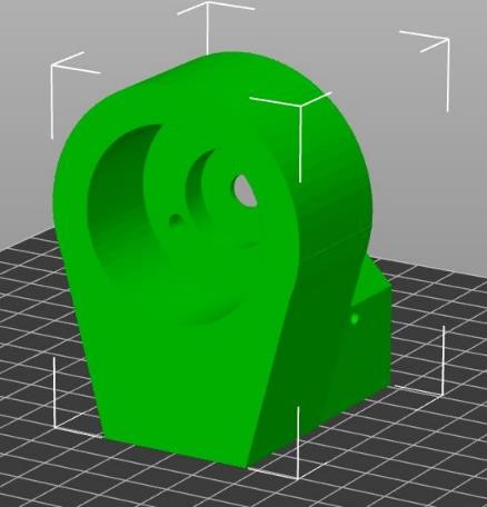
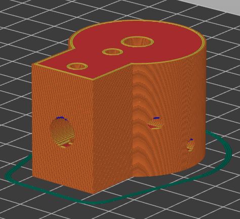
• Or like this (rotated 90 degrees):
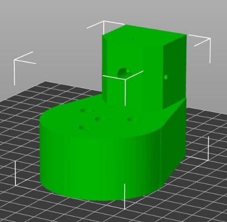
• Each one of these prints has pros and cons. Depending on which dimensions I want to be more correct, which parts I’m allowing larger tolerances, which parts I’m allowing for more inaccuracy of the print, and which way I would like the part to be strongest. In this case, I went with the 2nd image for the first test.
• Sliced the part on Prusa Slicer. Printed it on an Ender 3 in PLA. 30% adaptive cubic infill, 3 top/bottom layers, 3 perimeter layers. About a 3 hour print time.
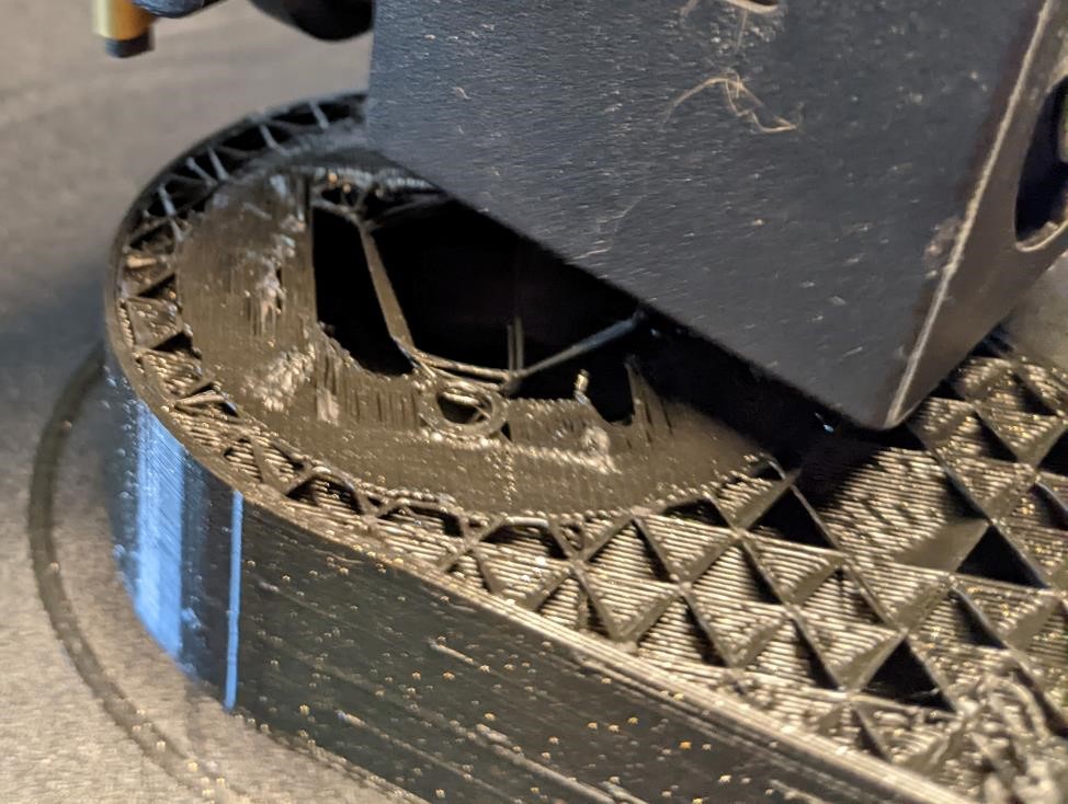
• The part had a couple of issues during printing (I knew this would be the case.) There was a very large, unsupported roof on the part, which being unsupported would not print well. Having experience, I knew the first few layers would be almost spaghetti, but the rest of the layers above it would print fine. And since the layers that would print poorly were not important, I printed the part as is. Here you can see an image showing what these layers looked like. (Why not just print it with supports? Because I’m impatient, and this is a prototype. I didn’t want to wait the extra 1 hour for supports to be printed.)
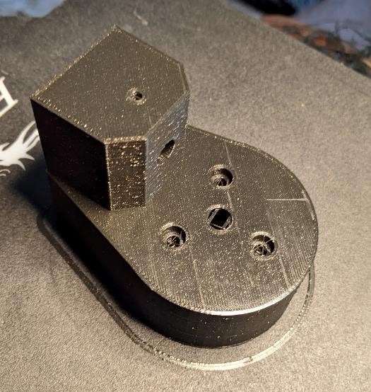
• Here’s what it looks like finished:
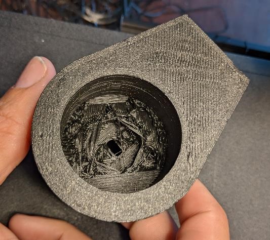
• Here’s what the underside looks like. Not pretty, but a minute with a knife cleans this up well enough to make sure that the fitment is good, that the bolt holes are in the correct location, the counterbores work, etc.
• When finished, the hole for the rod (which was designed as 8 mm, ended up printing 7.85 in X axis, but 8.2mm in Z. These types of inconsistent hole sizes are normal in a consumer level 3d printer. The Carbon Fiber Rod is 7.65mm. I had designed this hole size to be parametric in OpenSCAD, so one quick change to shrink the as-designed size 0.02mm will hopefully make this a tighter fitment.
• The 3mm hole for a 6-32 set screw (yeah mixing units. Yay. But it’s what I have.) is almost perfect. But I’ve done this enough times, that I know 3mm (0.118”) is a good size for self-threading of 6-32 set screws (also 4mm bolts) into 3d printed plastic parts. And of course, these set screws are there as set screws. Their function is to hold parts in place, not for taking huge forces.
- Here’s the corresponding part that will hold the rod and connect to the spindle of the encoder; seen “sliced” on Prusa Slicer.
This came out well. Shrinking the diameter for the rod 0.2mm did the trick to a nice snug fit. Diameter for encoder shaft was just about right on as well.
2/1
Printed Test Parts
Once I printed out the two parts that will connect the rods together and bolted in the Omron rotary encoder. It fit very nicely (even with the horrible surface finish of the 3d print.) The through bolt holes were the correct spacing and size. The counterbores worked perfectly. The set screws worked wonderfully (there are a lot of extra holes for set screws to allow for experimentation.). I installed two un-cut arrow shafts and installed the encoder. The physical fit was great, and the arm motion worked well.
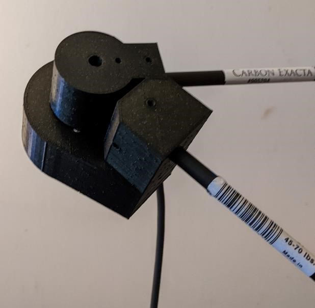
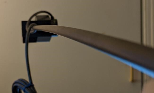
Bent Shaft
One thing I noticed when I was first fitting this unit together was the effect the relatively light weight of the encoder had on a 30” (~750mm) arrow shaft, when the arrow shaft was held at the very end. In the image below you can see the bend. (This behavior was fully expected, I’m just including this here because I think it’s neat and for educational purposes. I didn’t have any way to predict this behavior (I can’t do FEA) and I wanted to get an idea about the stiffness of these shafts before continuing on to a final design.)
- Worked on designing a bearing system for the base of the part in order to support the weight of the entire device on something other than the bearing of the rotary encoder.
Ball Bearings
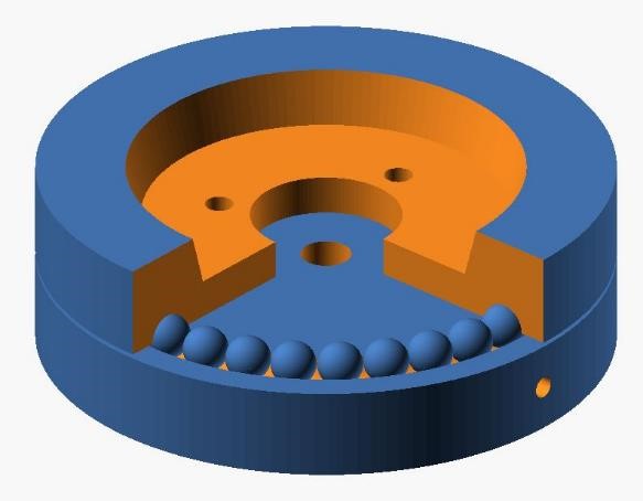
From the get go, I’ve thought that it would be necessary to help stabilize the rotating section of the base and I could not simply rely on the bearing of the encoder. I wanted to try and create a bearing around the outside of the base to see if I could help support it. Frankly, I’m not sure how well this will work. 3d printed bearings are antithetical to actual ball bearings.
I have steel ¼” ball bearings already, and using them on plastic doesn’t seem like such a good idea for longevity. Buying a large bearing designed for this purpose would be much smarter, especially on a project like this that is based around accuracy. But regardless, I’m going to at least give it a try and see how it works. Because why not?
I designed a test piece to start with. The idea is to use ¼” ball bearings that will fit in cut outs within the base and the top rotating part of the base. This is more of a thrust bearing style, but that should be all I need. I modelled it in OpenSCAD and it’s based on the actual base of the arm. I had to change the diameter of the race of the bearing in order to get 32 balls to fit with a minimum of space between each ball.
I have not yet had time to print this and test it.
Early materials list
-
Starting to price out parts and build a more complete materials list.
- 4 Omron style rotary encoders 1000 ppr or better - $30/piece
- About 30 m3 by 8 bolts
- About 10 6-32 set screws
- 2 to 3 arrow shafts (what length will each arm be?)
- 1 roll of PLA filament for 3d printing
- 50 ¼” POM ball bearings
- 4 attiny85’s and necessary support electronics
- 1 AVR and support electronics for a diy arduino.
- 12 ¼” non-chrome plated steel ball bearings (52200 steel.)
- 8 1/8”x 1” dowel pins
-
Started to think about how to test accuracy and precision of arm.