6a. 3D Scanning and printing Group Project
Week 5 - 2/23/22
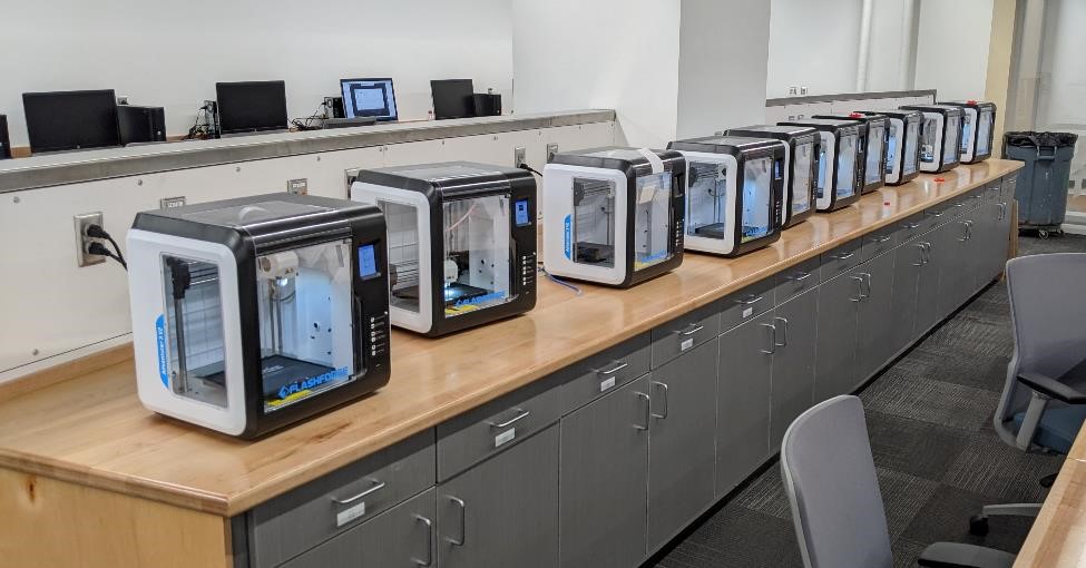
The group assignment was to classify and test our 3d printers’ capabilities.
Testing was done in the CPCC FabLab with Flashforge Adventure 3v2 printers.
FYI: Don’t buy these printers, they suck.
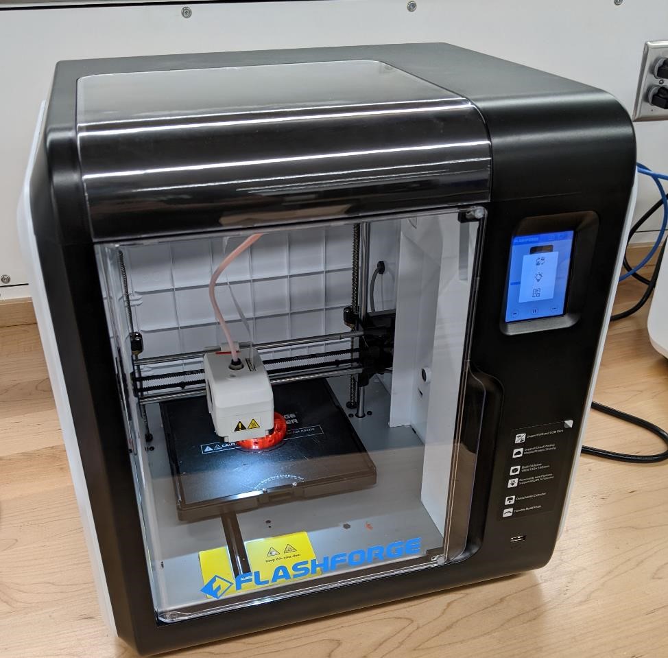
Don’t buy one of these.
The bed size is tiny (6” x 6”). Access to the hot end, extruder, the rest of the printer is non-existent. The bed is “self-leveling” which means it just has some soft springs that allow the bed to be pressed down by the extruder when printing.
These printers also seem to break down fairly quickly. And good luck buying parts for it.
That said, when it prints, it prints fairly well. But printers break, and filament gets jammed. I want a printer that is easy to fix when necessary.
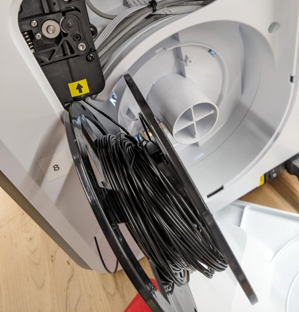
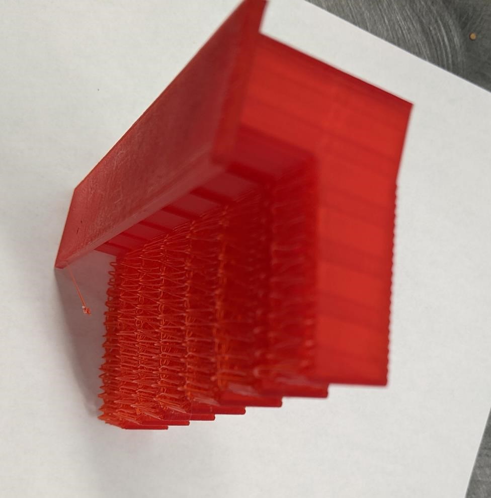
One of the reasons you shouldn’t buy one is that they use a non-standard sized filament spool, and an enclosure, which means you have to rely on the flashforge filament or transfer filament to smaller spools. And when you transfer filament to smaller spools, this happens:
We used about 8 of the flashforge printers to help increase productivity.
The printer filament was a flashforge transparent red PLA, which had absorbed way too much humidity and had become very brittle, causing a large number of failed prints.
The slicer software is the “ForgePrint” software that I believe is a simplified Cura wrapped in a flashforge skin. It too sucks (even though it’s based on Cura which I have no problem with.)
The vast majority of these printes were printed at the flashforge slicer software defaults, with some minor changes. There are exceptions, and they are noted where applicable.
Major Slicer Settings: - No Raft - 15% infill - 0.28 layer height
The images below can be opened in another window at full resolution to better see the data. They contain the default settings used for these tests.


Garrett used Prusa Slicer, but with very similiar settings.
The filament used for these test was Flasforge Red Transparent PLA at the FabLab, and eSun yellow silky PLA on Garrett’s prints.
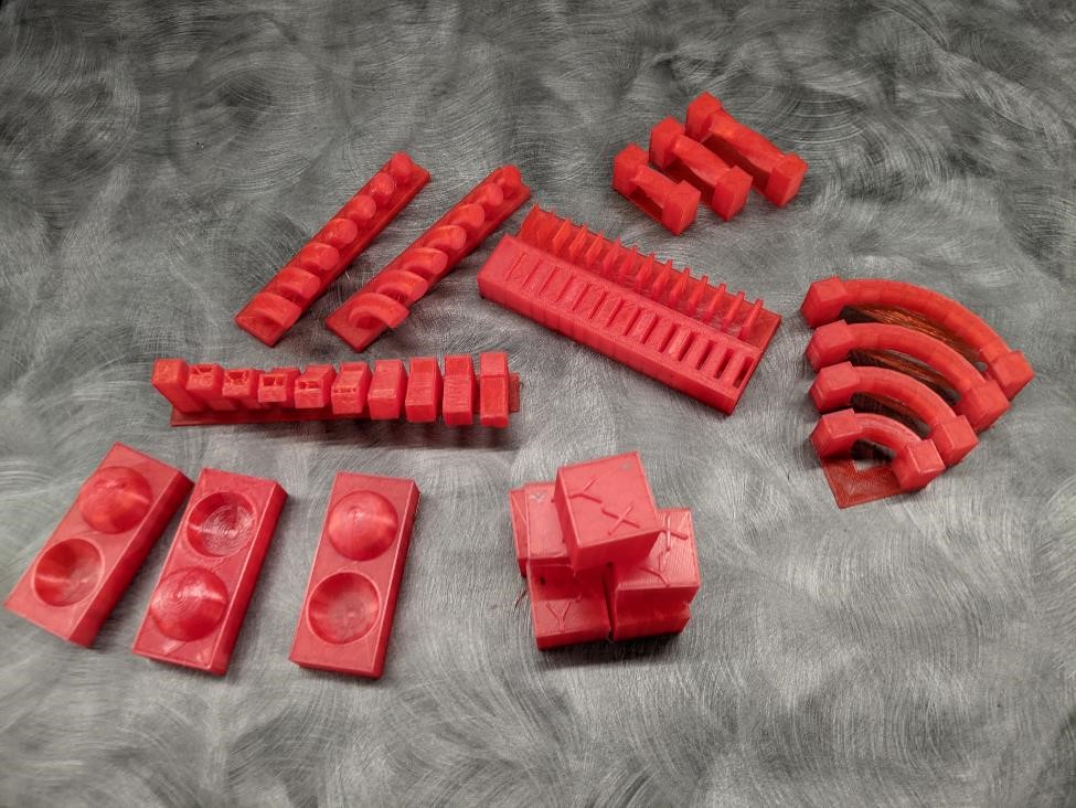
Test Parts
The following is the OpenSCAD code for the test prints.
Overhangs Test
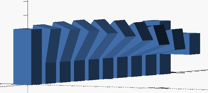
The printed parts worked surprisingly well. Even the 90 degree overhang printed exceptionally well. Sure there was a bit of spaghetti on the underside, but a bare minimum. I think a large amount of the success can be attributed to PLA’s low temperature and glass transition temps, and very high cooling to “freeze” the filament in mid-air.
This was so succesful, I want to see if there is a limit to how long an overhang can be.
The Code:
//sgn feb 2022
//over hangs test for 3d printing

$fn = 32;

angles();

module angles(){

for( n = [0:9]){

//lower part
translate([n * 20 - 7.5,-7.5,0])
cube([15,15,20 + (n * 1.3)]);

//angle
translate([n * 20 - 7.5,-7.5,15])
rotate([n * 10,0,0])
cube([15,15,25]);

//base
translate([n * 20 - 12,-15,-2])
cube([25,25,2]);
}
}
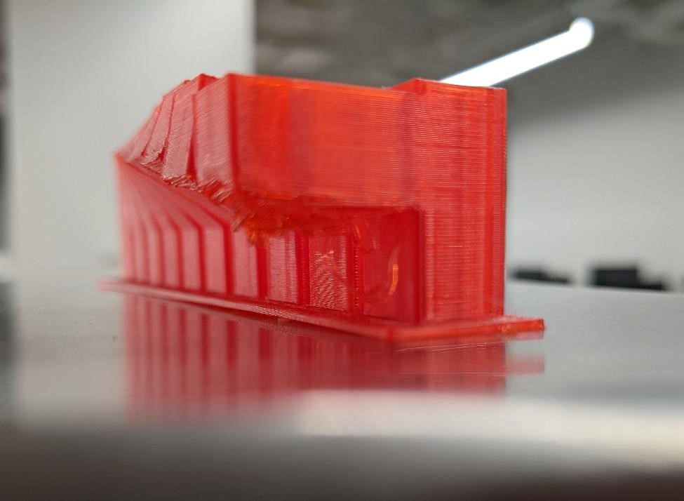
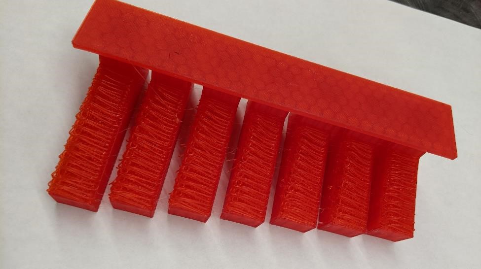
Long Overhangs
This came out nicely, and it shows how important the “weft and weave” of the fialment is when printed. It would be interesting to see how this print would have done if the entire print was rotated 90 degrees (or the undersides of these overhangs could be turned 90 degrees.)
//sgn feb 2022
//over hangs test for 3d printing
// is there a limit to how long an overhang can be?

$fn = 32;

overhangs();

module overhangs(){

for( n = [3:9]){

//lower part
translate([n * 20 - 7.5,-7.5,0])
cube([15,15,30]);

//angle
translate([n * 20 - 7.5,-7.5,15])
rotate([80,0,0])
cube([15,15,25 + (n * 3)]);

//base
translate([n * 20 - 12,-15,-2])
cube([25,25,3]);
}
}
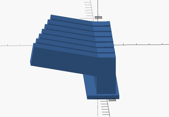
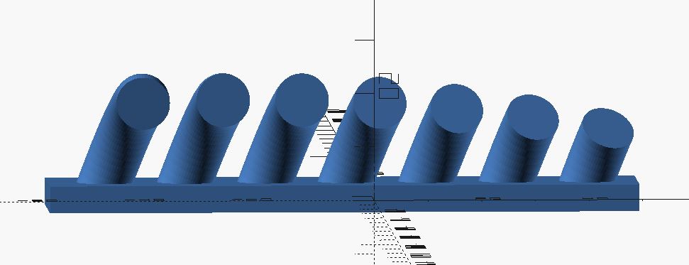
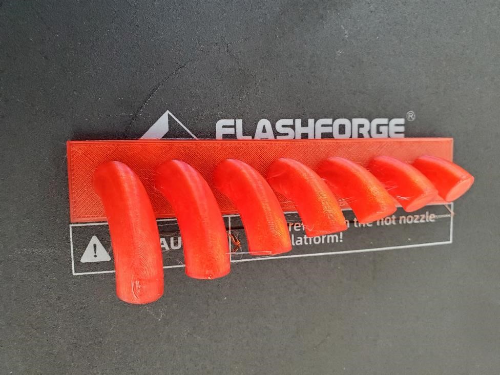
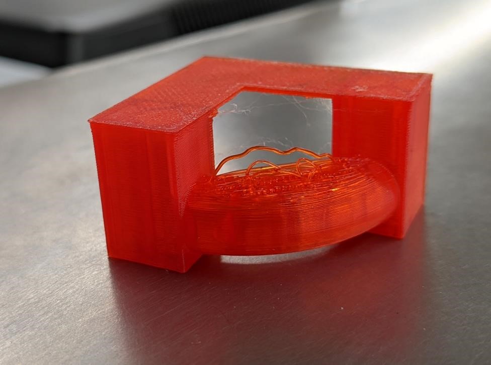
Curved Overhangs
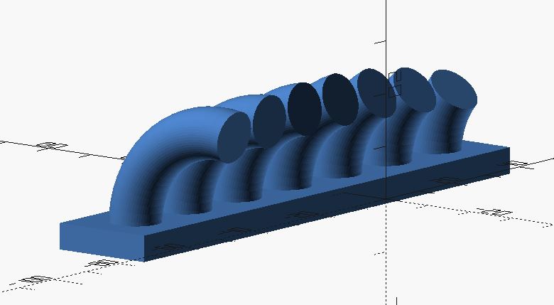
This test shows how exceptionally well printers can do with arches. While like the first test, there was some random strings, the structure survived in tact and continued to print without issue.
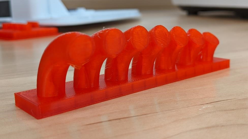
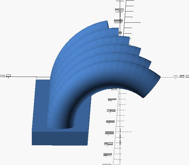
The first test went so well, I changed the n value in the below code to to 8 and 13 (for a much higher overhang that goes past 90 degrees and starts curving back towards the build plate. Surely this should be a printing disaster?)
Preview for the higher overhang test:
//sgn feb 2022
//curved overhangs
//most certainly will fail, but curious how it will fail.

$fn=32;

translate([100,0,0])
rotate([90,0,90])
for( n = [4:10]){

translate([0,0,n*-15])
rotate_extrude(angle=n*10, convexity=10, $fn = 64)
   translate([20, 0]) circle(d = 10);

//base
translate([10,-4,(n*-15)-10])
cube([20,5,20]);
}
Curved Overhangs 2
In retrospect, this test didn’t really test anything. I was wondering if a slight curve off-angle of the overhang would affect the printing quality. The answer is no. Even when you have a test that wasn’t necessary, you learn that it wasn’t necessary.
//sgn feb 2022
//curved overhangs 2
//most certainly will fail, but curious how it will fail.

$fn=32;

translate([100,0,0])
rotate([90,0,90])
for( n = [4:10]){

translate([0,0,n*-15])
rotate([20,0,0])
rotate_extrude(angle=n*10, convexity=10, $fn = 64)
   translate([20, 0]) circle(d = 10);

//base
translate([10,-3,(n*-15)-10])
cube([20,5,20]);
}
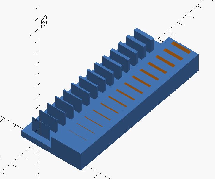
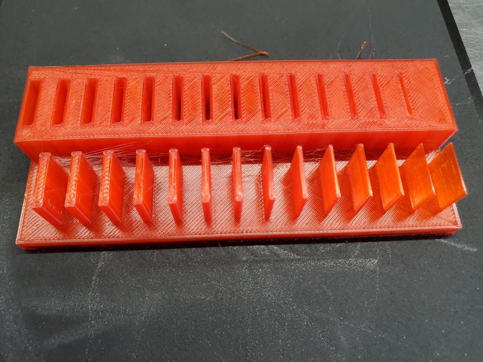
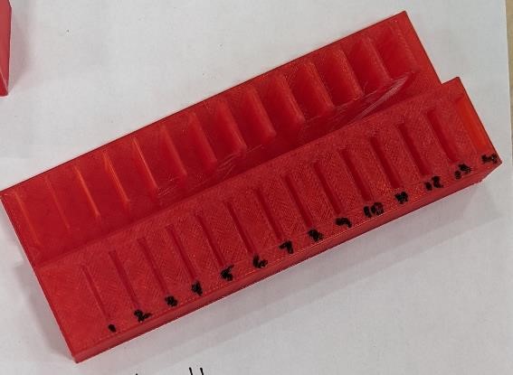
Thin Walls and Pockets
It would have been great to test these prints on an FDM printer as well as a resin printer; however our resin printers are out of action at the moment and we didn’t get a chance to compare and contrast the two printers. This also applied to every other test that would have been interesting to try with both a resin and fdm printers.
Measurements
Using basic metrology tools, we measured the sizes of the slots and walls. For the slots we used shim gages and gage blocks. For the walls we used a set of dial calipers.
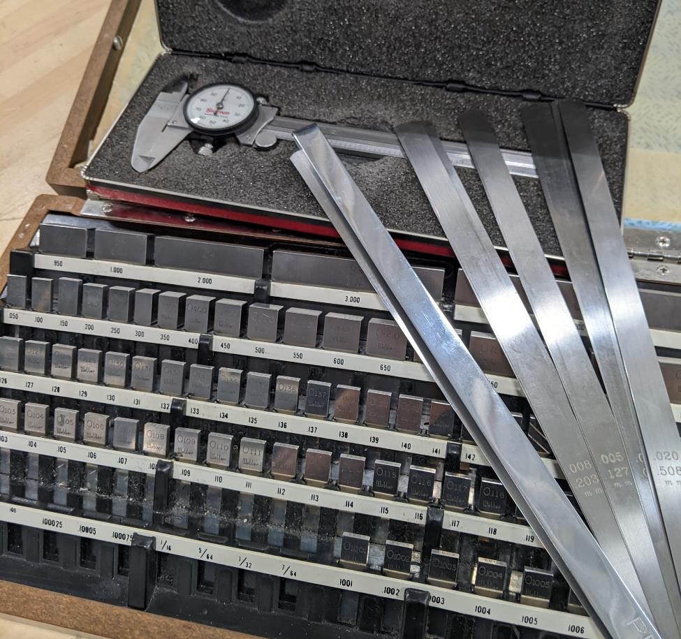
We numbered the walls and slots, starting with the smallest and getting larger.
| Number | Slot Width | Wall Width |
|---|---|---|
| 1 | 0.0015” didn’t fit. | 0.022” |
| 2 | 0.11” | 0.025” |
| 3 | 0.16” | 0.032” |
| 4 | 0.027” | 0.039” |
| 5 | 0.036” | 0.046” |
| 6 | 0.045” | 0.056” |
| 7 | 0.052” | 0.059” |
| 8 | 0.059” | 0.072” |
| 9 | 0.068” | 0.078” |
| 10 | 0.075” | 0.083” |
| 11 | 0.083” | 0.089” |
| 12 | 0.090” | 0.097” |
| 13 | 0.093” | 0.106” |
| 14 | 0.107” | 0.116” |
//sgn feb 2022
//to test printability of thin walls and thin pockets

$fn = 32;

walls();

translate([0,-25,0])
pockets();

module walls(){

for( n = [0:14]){

//cubes
translate([n * 8 - 7.5,-7.5,0])
cube([n * 0.2,15,15]);

//base
translate([n * 8,0,0])
cube([8,25,5], center = true);
}
}

module pockets(){

for( n = [0:14]){
difference(){
//base
translate([n * 8,0,5])
cube([8,25,15], center = true);

//cubes
translate([(n * 8),-7.5,0])
cube([n * 0.2,15,15]);

}
}
}
Surface Finish
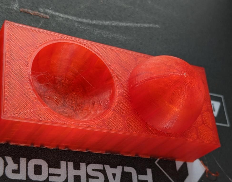
Sphere Test
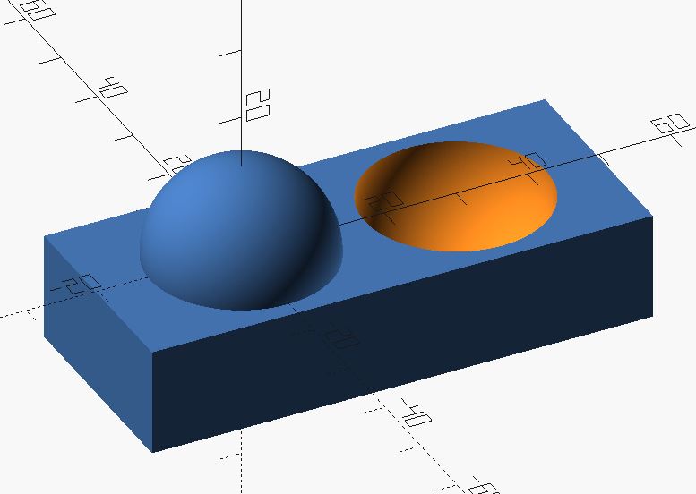
This test will be printed with various layer thickness (and variable layer thickness) and to get a better understanding of how layer height affects the surface, especially as a sphere is one of the best studies to show the affect of layer height and smoothing.
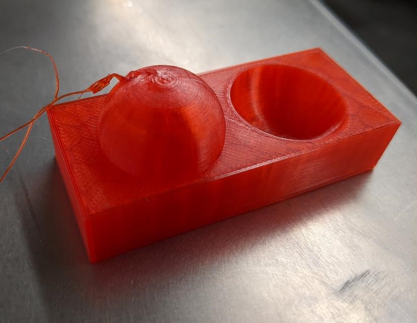
The first print came out very nice. However, Garrett may or may not have accidently told the printer to print again, causing it to jam a hot end into the top of the print. That possibly being the case, the large chunk of plastic missing from the top of the dome should not be held against the part and printer themselves.
Printed with a 0.1mm layer height.
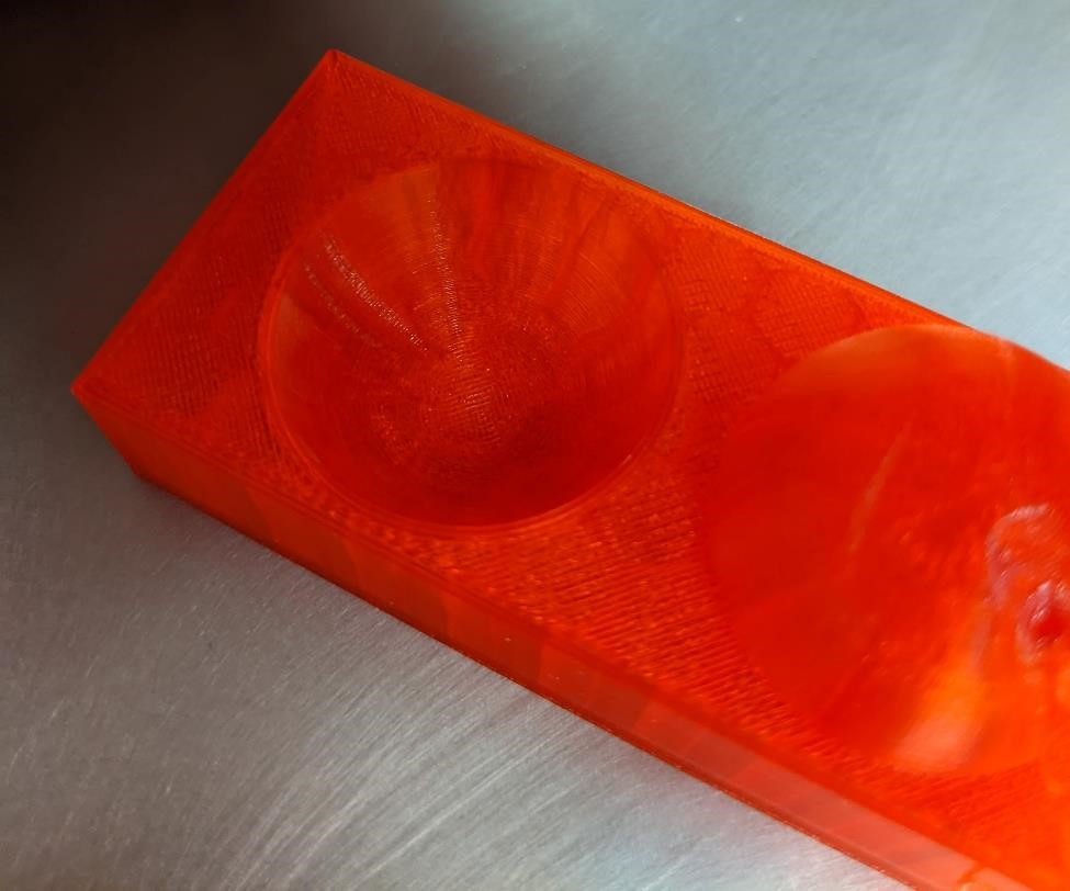
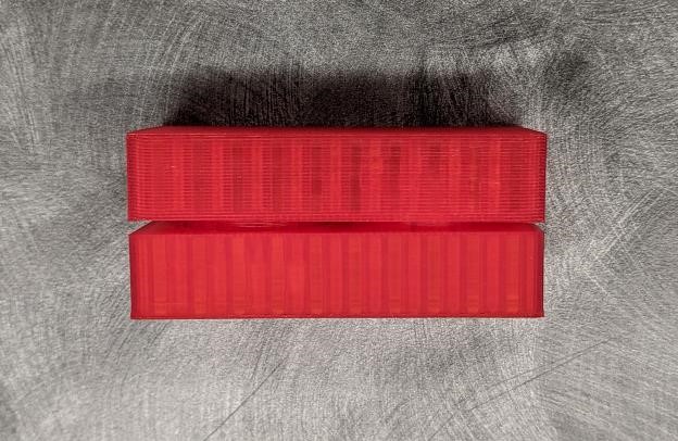
We are printing multiple pieces. One will be 0.10mm layer height. One will be 0.27mm layer height (printer’s default) and One may be variable layer height (though in preview, it appears that this makes no noticeable different, and the printer essentially stays in 0.10mm layer mode for almost the entirety of the print.)


Below are the prints printed with different layer heights. The quality of the surface finish is very noticeable, especially near the top of the hemisphere, and the bottom of the bowl.
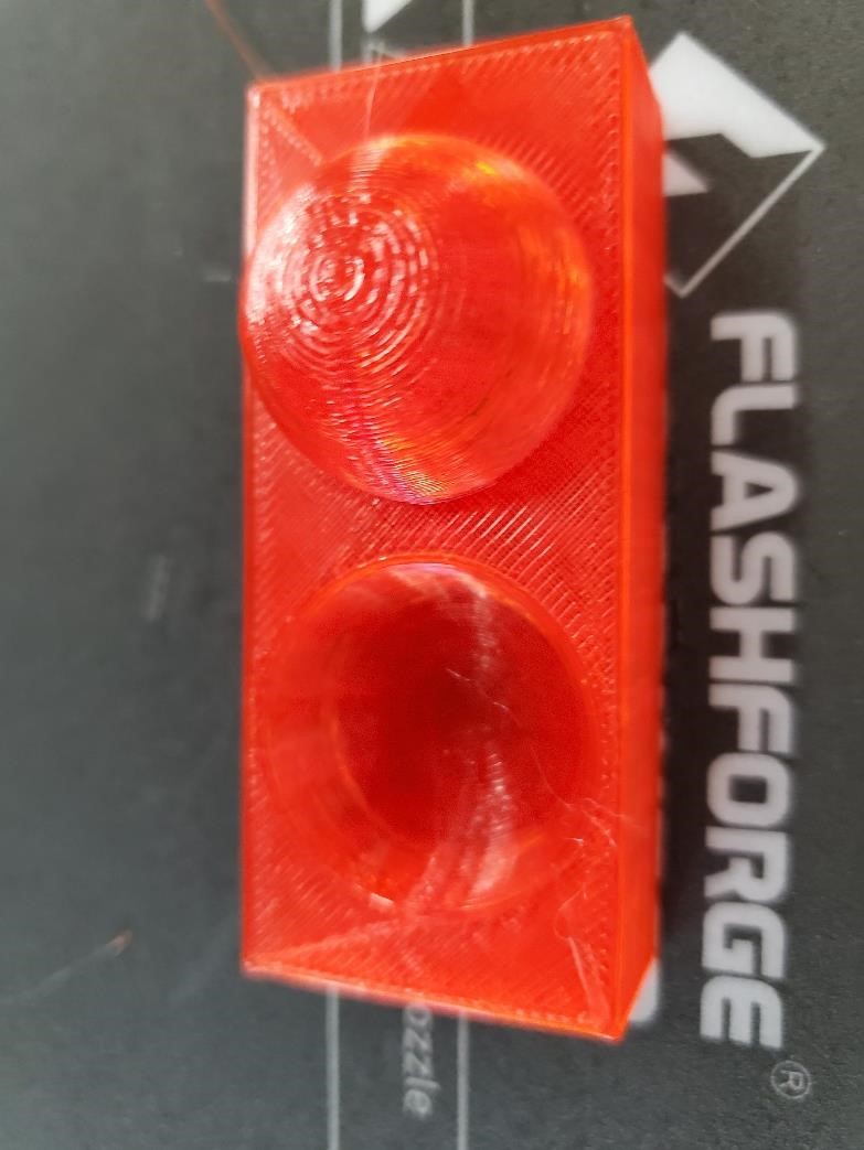
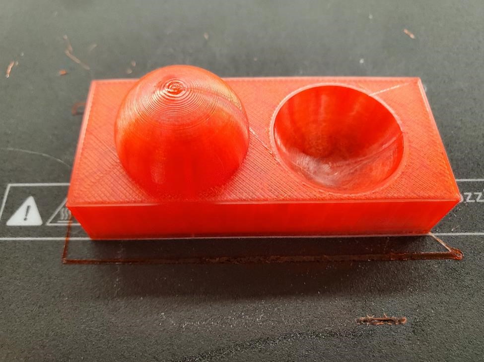
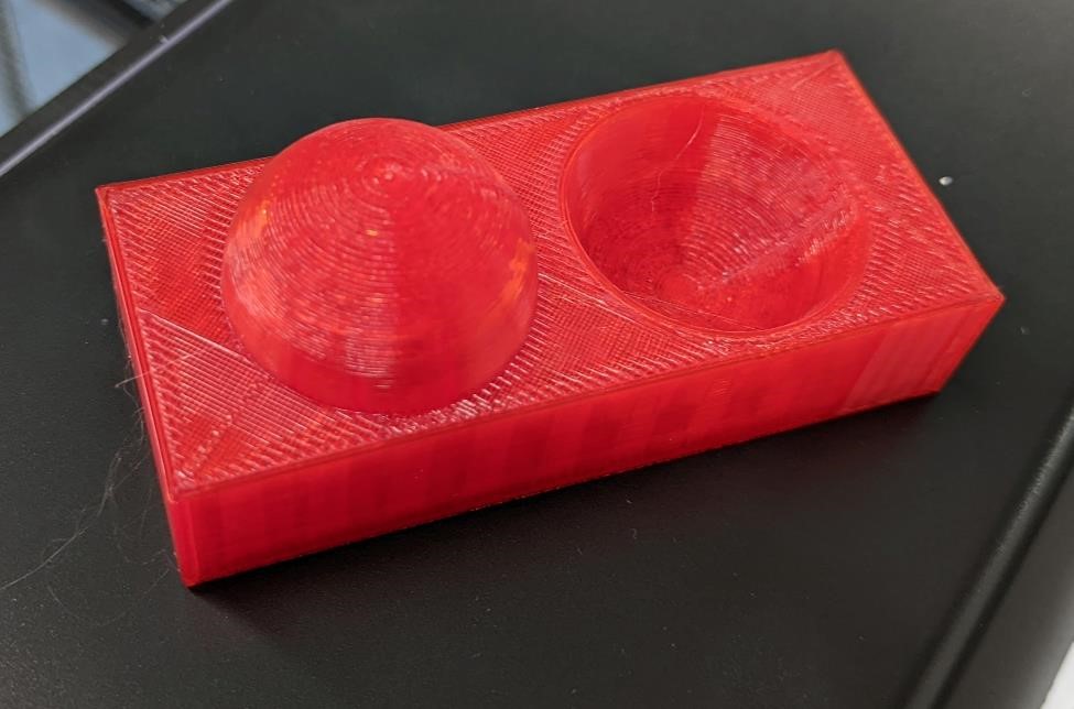
They’re close enough in size, and smooth enough that they almost fit together. This is a pretty good fit given the constraints of 3d printing.
//sgn Feb 2022
// to test surface finish of layer heights

$fn = 128; //256 for stupid high resolution

difference(){
union(){
translate([0,0,0])
sphere(d = 25.4);

translate([15,0,-8])
cube([70,30,15], center = true);
}

translate([30,0,0])
sphere(d = 25.4);
}
Simple Bridge
This was a print that measured how well the printers handled bridging. These printe started with a 2mm gap between the towers, and increased that 10 times. The bridges worked out great.


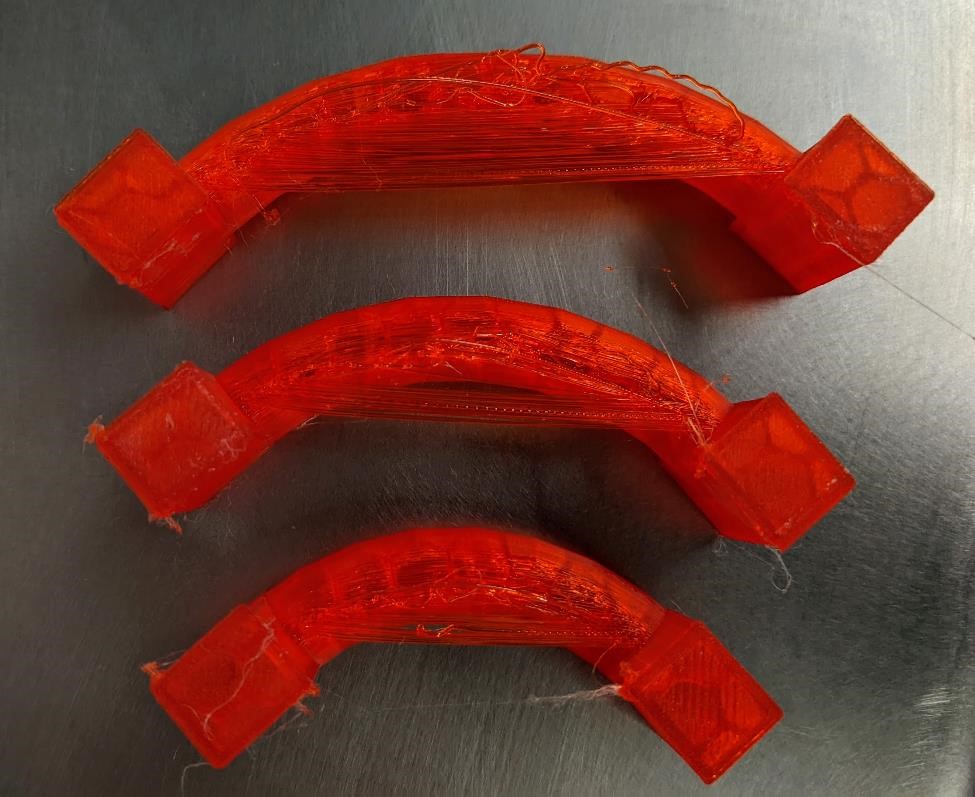
Curved Bridge 1
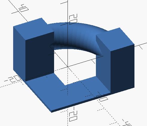
This was an experiment to see how non-linear bridges would work. And while of course the first few layers are linear themselves, I was curious how this would affect the overall print. To my surprise, this printed much better than expected. The below examples are trying to push this to the breaking point.
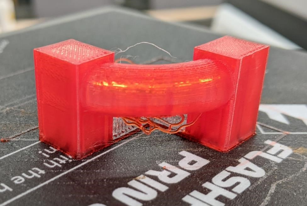
and upside down, which shows you a good view of how the part printed.
//sgn feb 2022
// single curved bridging test
//most certainly will fail, but curious how it will fail.

$fn=32;

rotate_extrude(angle=90, convexity=10, $fn = 64)
   translate([20, 0]) circle(d = 10);

//tower 1
translate([-10,15,-14])
cube([12,10,20]);

//tower 2
translate([15,-6,-14])
cube([10,12,20]);

//thin base
translate([0,-6,-14])
cube([25,12,1]);

translate([-10,-6,-14])
cube([12,25,1]);
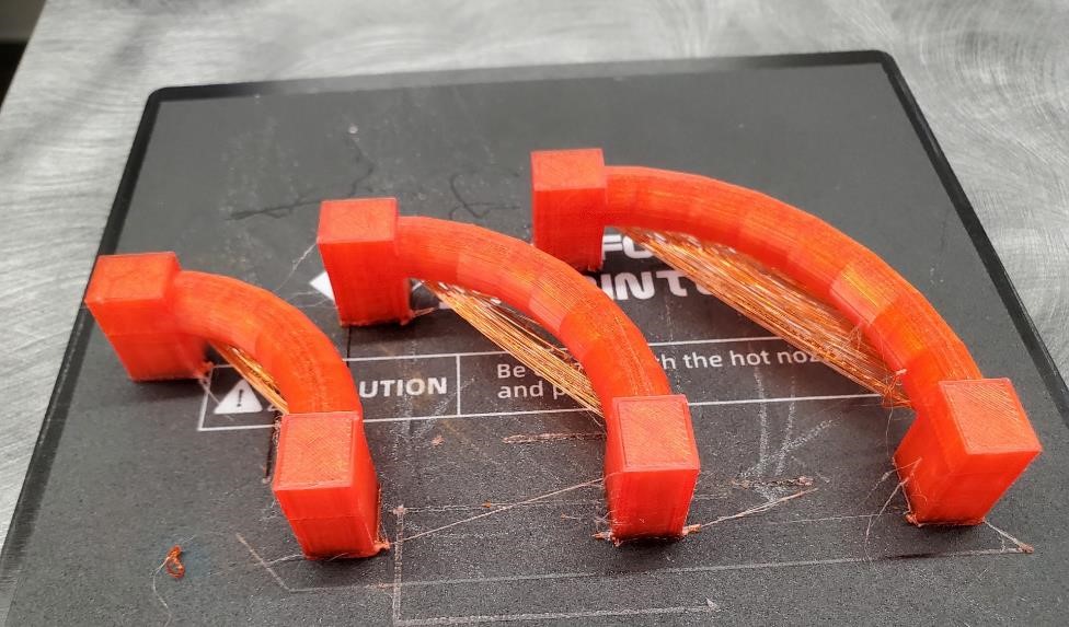
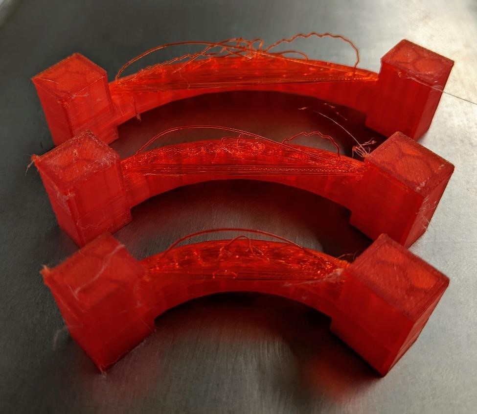
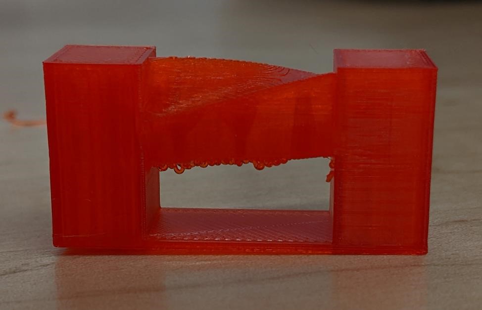
Curved Bridge 2 Test
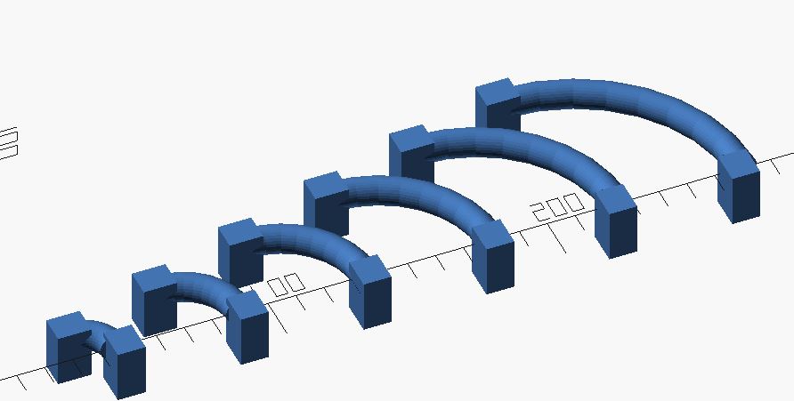
These prints amazed me. It goes to show how well PLA works with good cooling. I’m surprised they didn’t as well as they did. Obviously, the early layers are pulled out (and I wonder how much of the “bridging” options in the slicer had to do with this. This would be worth further investigation.)
But the later layers managed to build themselves on top of the first few layers and resemble the final design.
//sgn feb 2022
// curved bridging test
//most certainly will fail, but curious how it will fail.

$fn=32;

for( n = [1:6]){

translate([n * 35,0,0])
rotate_extrude(angle = 90, convexity=10)
   translate([n * 10, 0]) circle(d = 10);

//tower 1
translate([(n*35)-8,(n*10)-5,-14])
cube([12,10,20]);

//tower 2
translate([(n*34)+(n*11)-5,-10,-14])
cube([10,12,20]);

}
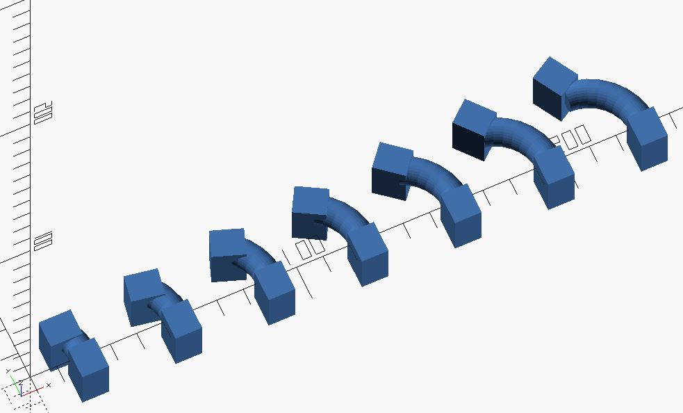
Curved Bridge 3 Test
With the results of the above two curved bridge tests, we didn’t feel the need to test this one as well.
//sgn feb 2022
// curved bridging test
//most certainly will fail, but curious how it will fail.

$fn=32;

for( n = [0:6]){

translate([n * 35,0,0])
rotate_extrude(angle=(30 + (n * 10)), convexity=10)
   translate([20, 0]) circle(d = 10);

//tower 1
translate([(n*32)+10,(n*1.5)+9,-14])
rotate([0,0,15*sin(n*-30)])
cube([12,10,20]);

//tower 2
translate([(n*35)+15,-10,-14])
cube([10,12,20]);

//BASE 1
hull(){
translate([(n*32)+10,(n*1.5)+9,-14])
rotate([0,0,15*sin(n*-30)])
cube([12,10,2]);

//BASE 2
translate([(n*35)+15,-10,-14])
cube([10,12,2]);
}
}
Calibration Cubes
To measure cubes that aren’t just printed perfectly in line with x and y axis.
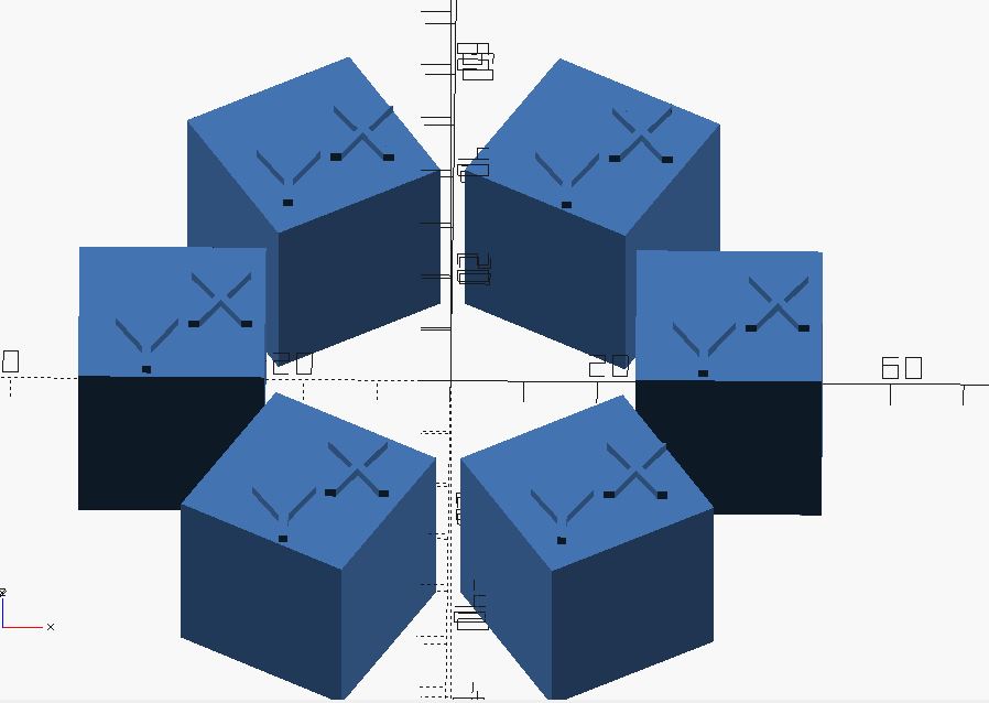
The printed calibration cubes. Good surface finish, good accuracy.
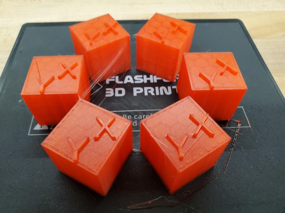
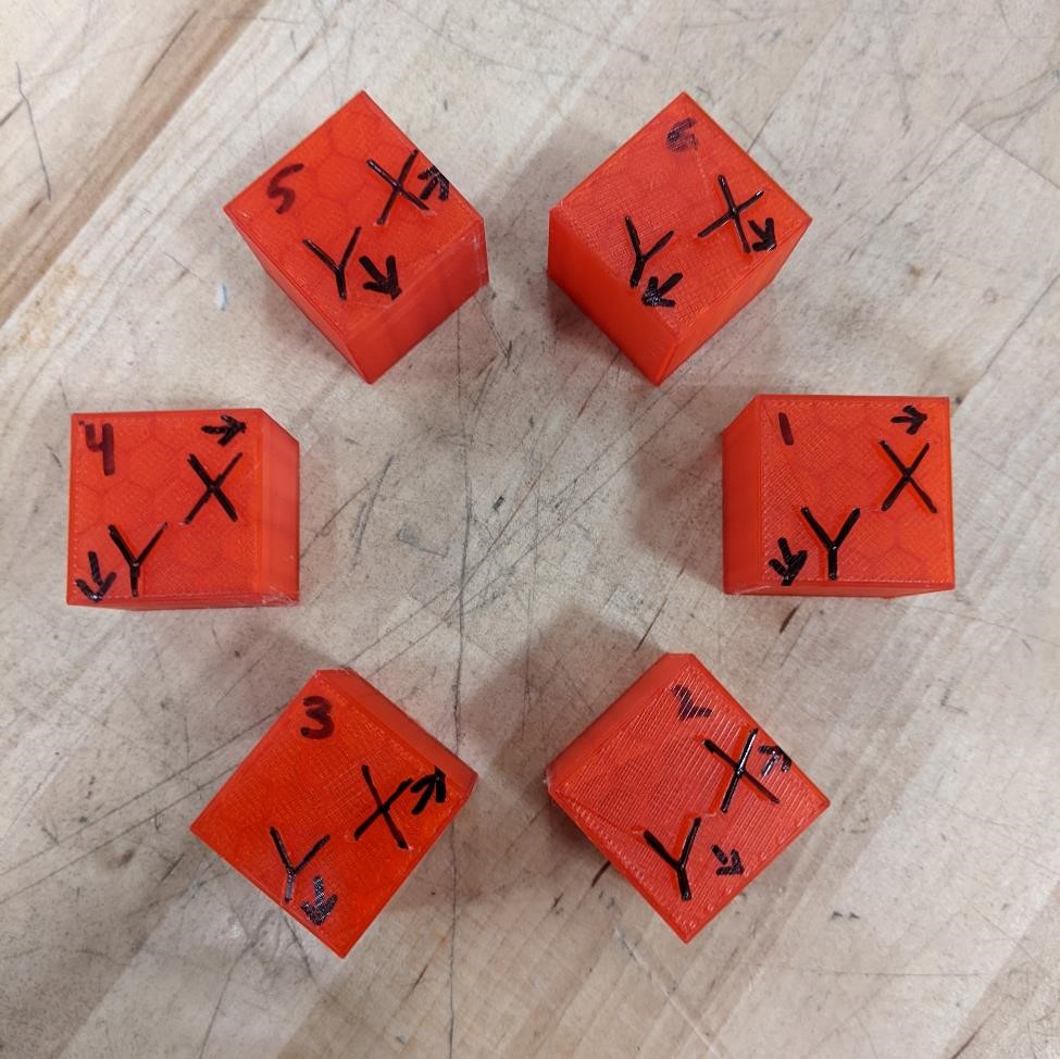
The below is the chart and the measured value for the X and Y dimensions. Because most of these cubes did not print exactly along the X/Y plane, they were arbitrarily given an X/Y designation for eas of measurement/record keeping.
The accuracy of this printer is quite excellent. We hypothesized that once the printer got out of straight line, x/y moves, there would be more inaccuracy, and while this is the case, the differences are so small as to likely be measurement or some other type of error.
| Cube Number | X | Y |
|---|---|---|
| 1 | 1.003” | 1.000” |
| 2 | 1.003” | 1.003” |
| 3 | 1.001” | 1.000” |
| 4 | 1.003” | 1.000” |
| 5 | 1.005” | 1.001” |
| 6 | 1.001” | 0.999” |
//sgn feb 2022
//calibration cubes checking non-xy coordinates
//make sure to align respective x and y axis.

$fn = 32;

calibration_cube();

module calibration_cube(){

for (n = [0:5]){

rotate([0,0,n*60])
translate([38,0,0])
cube([25.4,25.4,25.4], center = true);

//TEXT
//X
rotate([0,0,n*-60])
translate([38,0,10])
rotate([0,0,n*60])
translate([2,-3,0])
linear_extrude(4)
text("X", font = "Liberation Sans");

rotate([0,0,n*-60])
translate([38,0,10])
rotate([0,0,n*60])
translate([-8,-12,0])
linear_extrude(4)
text("Y", font = "Liberation Sans");

}
}
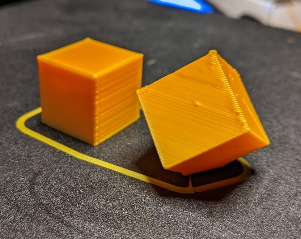
Calibration Cube 2

This is another calibration test looking at dimensions, but seeing how they are affected when not printed along the X, Y, and Z axis. The cubes are designed to be 20mm x 20mm x 20mm. One is the control, and one is printed at rotation of approximately 45, 40, 0.
Obviously, the X, Y, and Z planes do not line up exactly with the second cube. But for the sake of naming, we labelled them with X, Y, and Z, trying to get them in a somewhat similar plane.
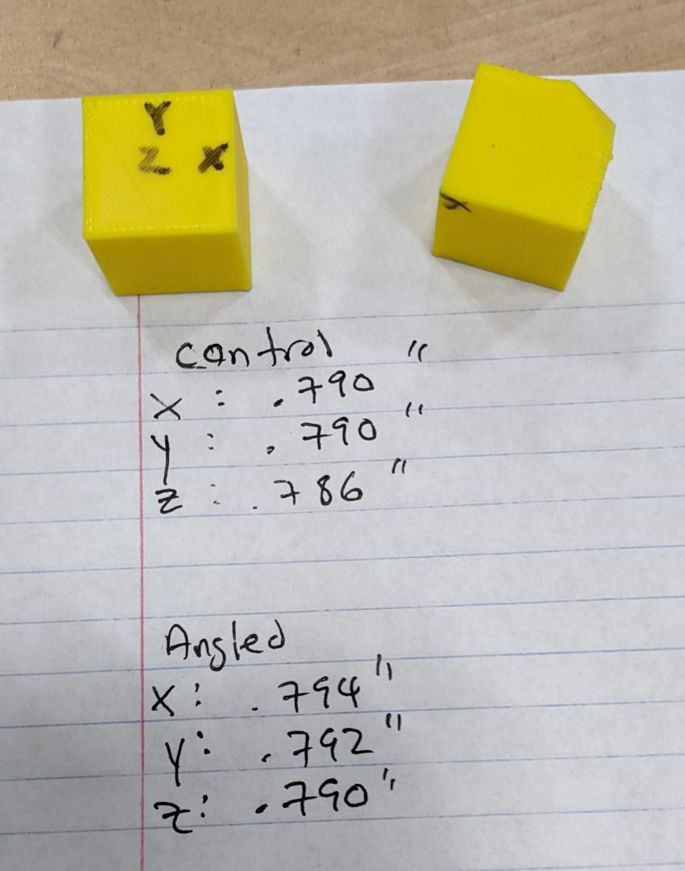
Garrett’s printer
Silk yellow filament
Control Cube
| Dimensions | Measurement |
|---|---|
| X | 20.1 mm |
| Y | 20.3 mm |
| Z | 19.65 mm |
Angled Cube
| Dimensions | Measurement |
|---|---|
| X | 19.9 mm |
| Y | 20.3 mm |
| Z | 20.5 mm |
All things considered, pretty good results. But the Z on this printer could be tuned a bit better, because in this particular case, there is an 0.85mm difference between the two prints.
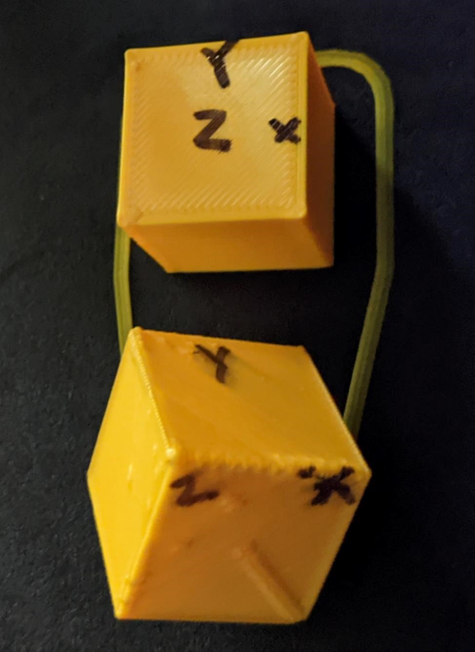
FlashForge Printer
The yellow filament
Control Cube
| Dimensions | Measurement |
|---|---|
| X | 20 mm |
| Y | 20.01 mm |
| Z | 19.96 mm |
Angled Cube
| Dimensions | Measurement |
|---|---|
| X | 20.16 mm |
| Y | 20.11 mm |
| Z | 20.06mm |
The results from the flashforge were much more consistent and much closer together.
//sgn feb 2022
// calibration cube test - non XYZ planar
//includes control

$fn = 32;

difference(){
rotate([45,35,0])
cube([20,20,20], center = true);

translate([0,0,-23])
cube([20,20,20], center = true);
}

//control
translate([0,35,-3])
cube([20,20,20], center = true);
Pin Gage Test
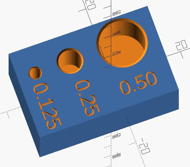
3d printers are notorious for creating undersized holes. I’m going to use this test and pin gages to determine what size holes these will actually print.
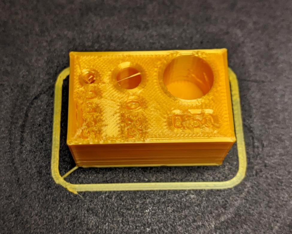
Not the best image, but you can see that already there are some issues with this particular print. There is a large amount of stringing, and some of these strings impinge on the hole. We’ll use a small needle file to try and clean up these strings before testing with the pin gages. It’ll be tricky to try and clean the strings without affecting the actual hole diameter.
One test was done with Garrett’s home printer (silk yellow filament) and one was done with CPCC’s fablab printers (transparent red filament.)
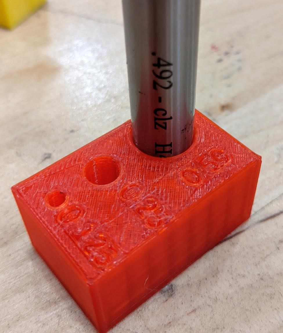
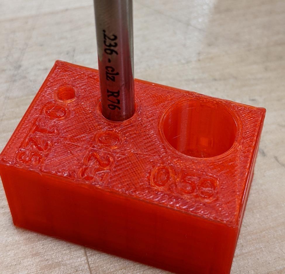
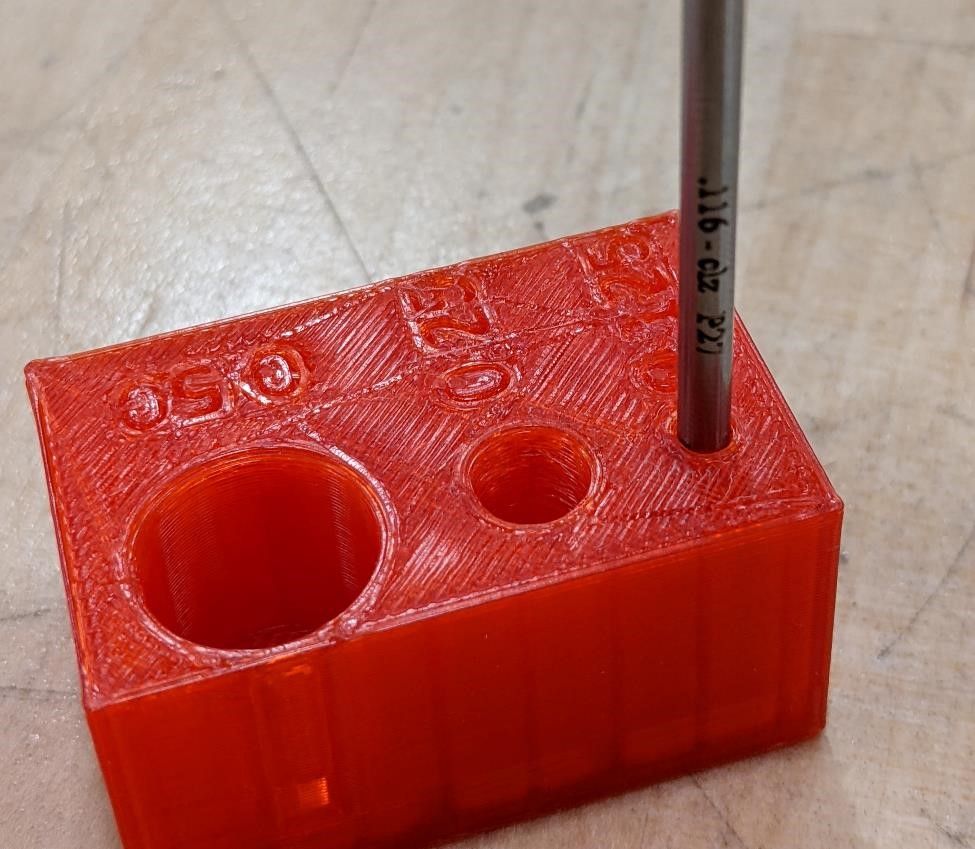
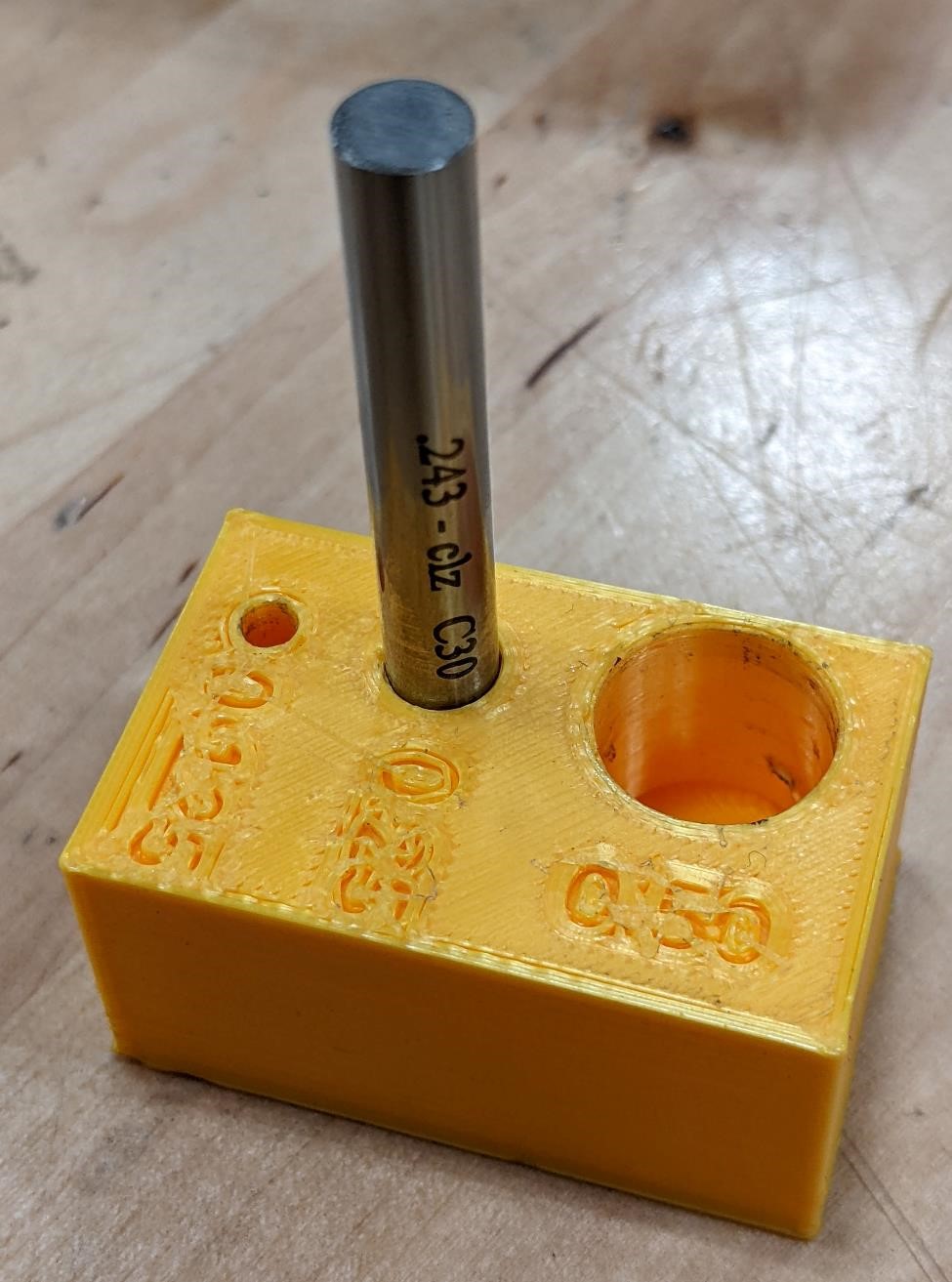
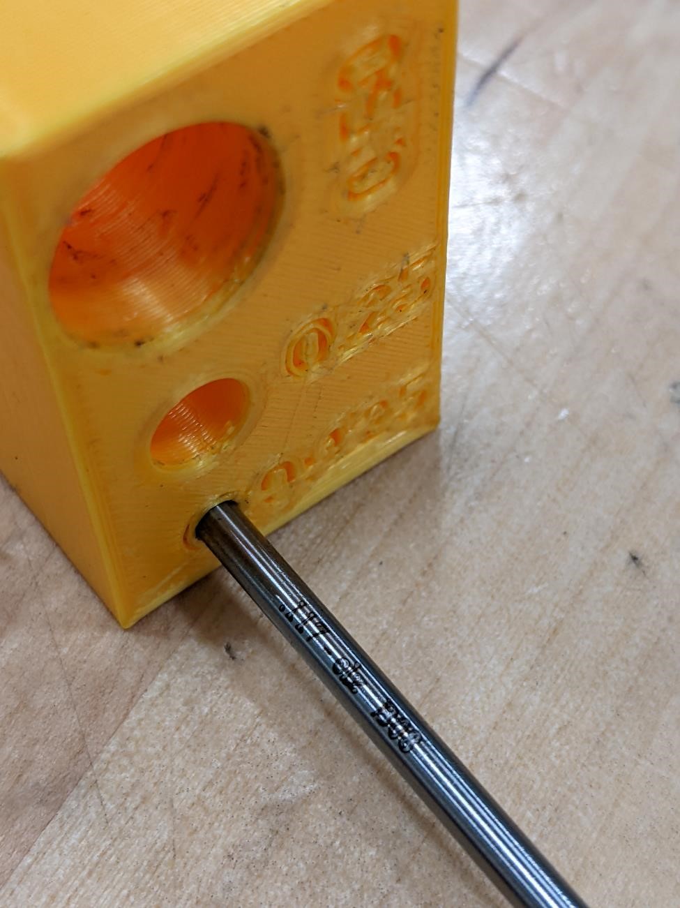
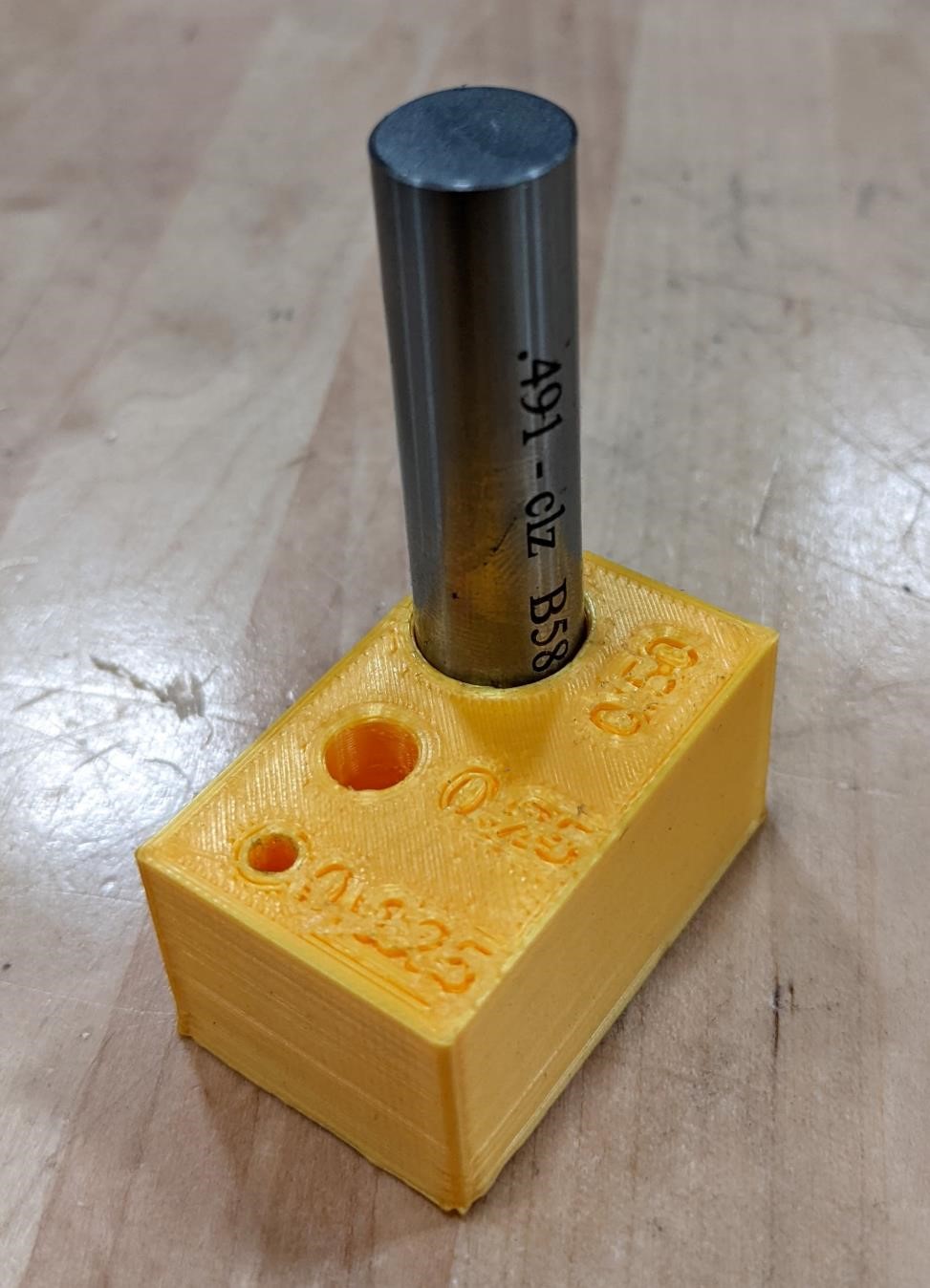
Results
We very briefly cleaned the holes of any loose filament and “strings” and then used pin gages to determine the size of each hole for the two parts we printed (with two different printers and two different filaments.)
| Dimensions | Flashforge | Ender 3 |
|---|---|---|
| 0.125” | 0.116” | 0.117” |
| 0.250” | 0.236” | 0.245” |
| 0.500” | 0.492” | 0.491” |
//sgn feb 2022
//pin gage test for 0.125, 0.25, 0.5

$fn = 64;

difference(){
translate([-5,0,0])
cube([40,25,20], center = true);

//0.125"
translate([-20,5,5])
cylinder(d = 3.17, h = 20, center = true);

//chamfer
translate([-20,5,11])
cylinder(d1 = 3.17, d2 = 6, h = 3, center = true);

//0.25
translate([-10,5,5])
cylinder(d = 6.35, h = 20, center = true);

translate([-10,5,11])
cylinder(d1 = 6.35, d2 = 12, h = 3, center = true);

//0.5
translate([5,5,5])
cylinder(d = 12.7, h = 20, center = true);

translate([5,5,11])
cylinder(d1 = 12.7, d2 = 20, h = 3, center = true);

//TEXT
//0.125
translate([-22,2,9])
rotate([0,0,270])
linear_extrude(4)
text("0.125", size = 4, font = "Liberation Sans");

//0.25
translate([-11,-1,9])
rotate([0,0,270])
linear_extrude(4)
text("0.25", size = 4, font = "Liberation Sans");

//0.50
translate([0,-9,9])
rotate([0,0,0])
linear_extrude(4)
text("0.50", size = 4, font = "Liberation Sans");
}
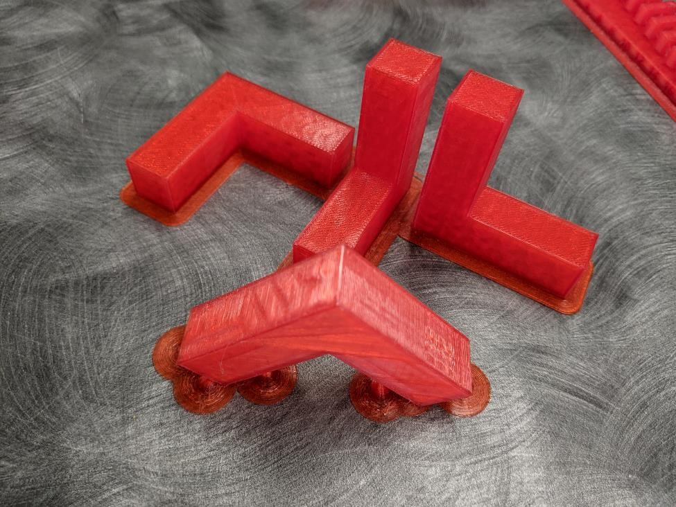
Ansiotropic Test
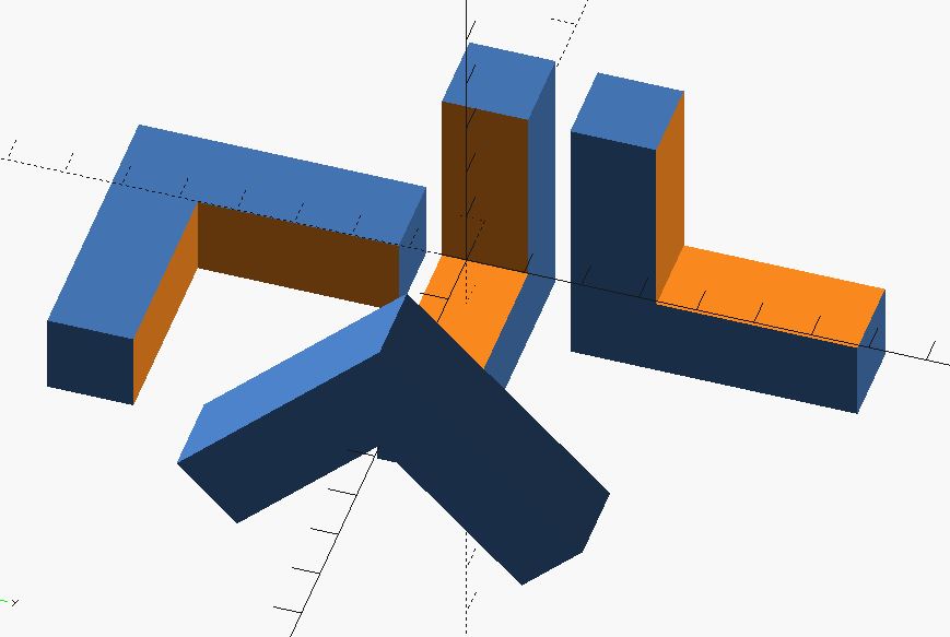
These are simply a set of four 90 degree angles printed in different planes. The idea would be to structurally test these members and see what their physical properties are based on being printed with the same settings on the same printer, how they differ based on their printing direction. Whether or not we have time to actually test these parts… well, that’s another matter.
see: https://www.tetonsim.com/blog/post/introduction-to-anisotropy-of-3d-printed-parts
//sgn feb 2022
//anisotropic test

ell();

translate([-17,40,0])
rotate([0,0,90])
ell();

translate([0,-40,-17.5])
rotate([90,0,90])
ell();

translate([40,0,-14])
rotate([0,135,90])
ell();


module ell(){

difference(){
cube([50,15,50], center = true);

translate([15,0,15])
cube([50,20,50], center = true);

}
}
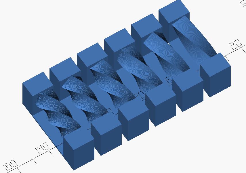
Twisty Bridges
Twisty Bridges 2
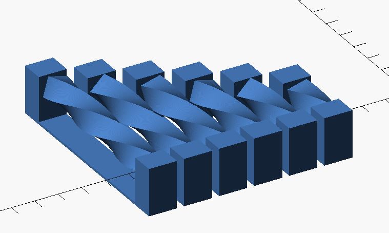
Again, I was expecting these to completely fail, but I was surprised at how fairly successful the print was.
//sgn feb 2022
// weird twisty bridging test
//most certainly will fail, but curious how it will fail.

$fn = 32;

for(n = [2:7]){

translate([0,(n*15)+5,0])
rotate([0,90,0])
linear_extrude(n*10, convexity = 10, 20, twist = n*30, slices = 300, $fn = 4)
circle(d = 12);

//tower 1
translate([-10,n*15,-14])
cube([10,12,20]);

//tower 2
translate([n*10,n*15,-14])
cube([10,12,20]);

//thin base
translate([0,n*15,-14])
cube([n*10,12,1]);
}
Twisty Bridges 3
//sgn feb 2022
// weird twisty bridging test
//most certainly will fail, but curious how it will fail.

$fn = 32;

for(n = [2:7]){

translate([0,(n*17)+5,0])
rotate([0,90,0])
linear_extrude(30, convexity = 10, 20, twist = n*30, slices = 400, $fn = 4)
circle(d = 12);

//tower 1
translate([-10,(n*17)-1,-14])
cube([10,13,20]);

//tower 2
translate([30,(n*17)-1,-14])
cube([10,13,20]);

//thin base
translate([0,(n*17)-1,-14])
cube([30,13,1]);
}
Ball Bearing Test
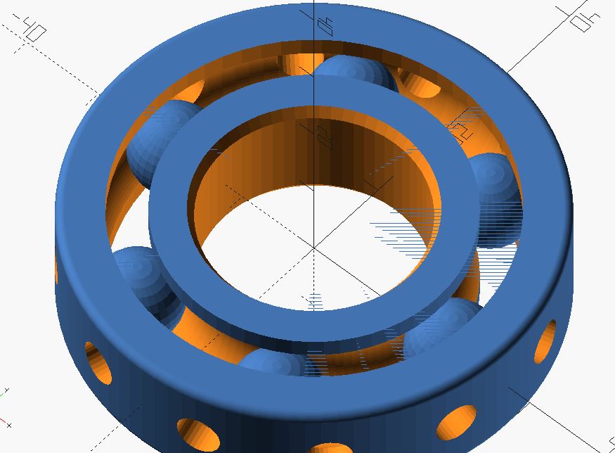
Each ball gets larger by 0.1mm. Want to find “perfect” size of clearance and fit.
One thing I noticed quickly, this printer had a lot of “stringing” ending up with a “hairy” print. It didn’t affect anything, but it’s just an observation.
This print is designed to uses support on plate only.
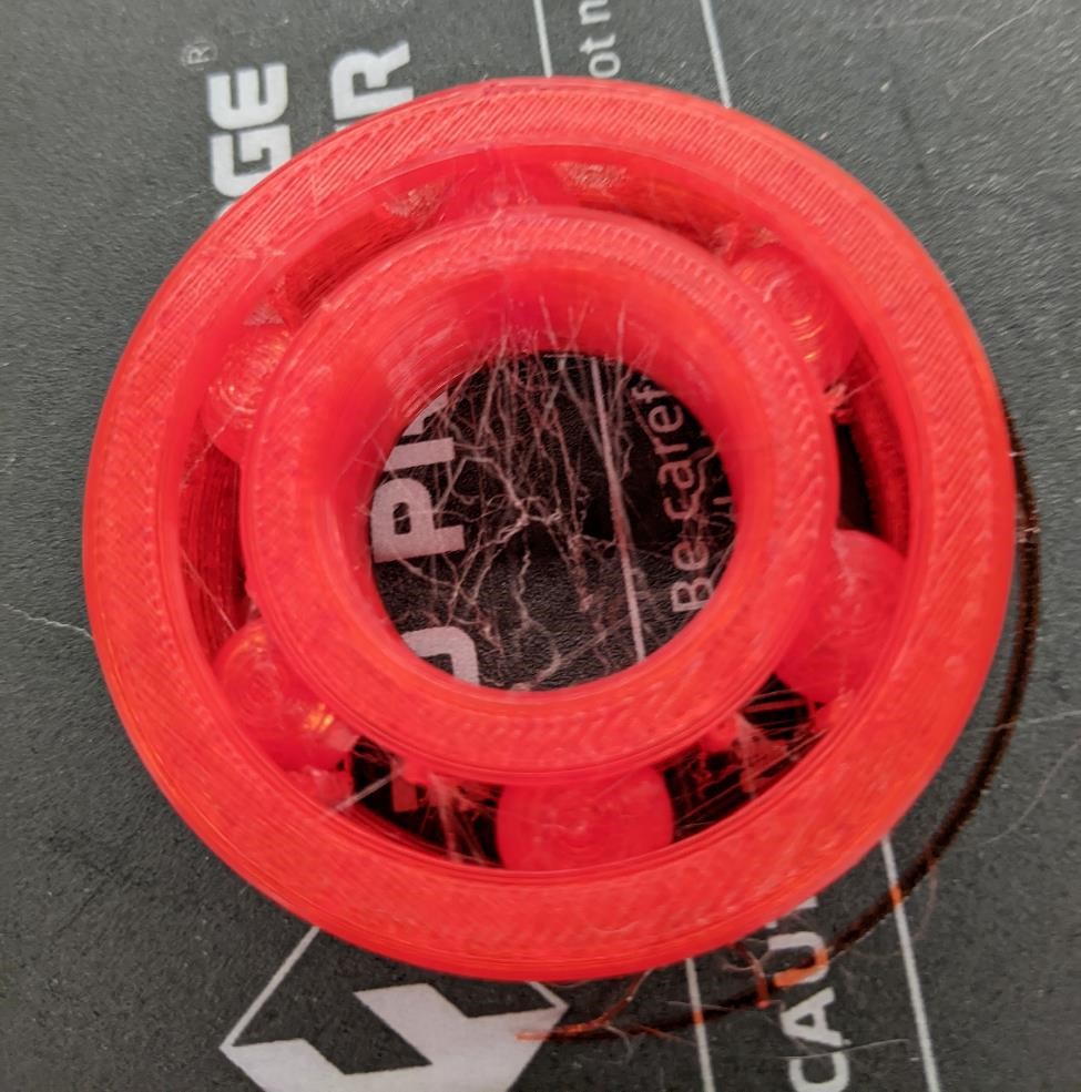
On this test print, only 2 of the balls were able to be dislodged. We will print a new one with a smaller variation (0.05mm instead of 0.1m) to see if that makes a difference.
//printable roller bearing test. Work In Progress.
//Find largest ball bearing that doesn't fuse to wall.
//sgn
//Original - June 2017
//modified feb 2022

//Print with support on build plate only.

//this code was never meant to see the light of day.
//changes to make:
//  parametric - figure out a few relationships
//  add cones (to make more printable, gets rid of some overhangs.)


$fn = 32;

//FOR ROLLER BEARINGS
bearings = 6;  //number of roller bearings
bearing_diam = 9.6;  //diameter of individual bearings
dangle = 60;  //angle of bearings (360/bearings)
rd = 19.35; //diameter of all bearings inside races

//FOR INTERNAL RACE
id = 25;  //internal diameter
id_width = 9.5;
id_top_width = 6;  //extra race size at top
idhe = 14;     //height of id

//FOR EXTERNAL RACE
od = 52;  //outer diameter
odhe = 14;  //height of od
od_bottom_width = 10;  //extra race size on bottom
gap = 13;   ///extra gap distance between races if wanted/needed


final();  //FINAL PRODUCT - USE TO PRINT


module final(){
difference(){
union(){
new_rollers(rd,0,0,bearings, bearing_diam, dangle);


new_inner_race(id, idhe, id_width, id_top_width);


new_outer_race(od, odhe, id, id_width, id_top_width, od_bottom_width, gap);
}
//to flatten bottom of bearings for printing
//translate([0,0,-15.52])  //-15.35
//cylinder(d = 80, h = 5);
}
}


module new_outer_race(od, he, id, id_w, id_tw, od_bw, gap){

difference(){
//cylinder(d = od, h = he, center = true, $fn = 64);
hull(){

cylinder(d = od, h = he - 3, center = true, $fn = 64);

rotate_extrude(convexity = 10, $fn = 100)
translate([0.5*od, (he * 0.5) - 1, 0])
circle(d = 2, $fn = 100);

rotate_extrude(convexity = 10, $fn = 100)
translate([0.5*od, (-he * 0.5) + 1, 0])
circle(d = 2, $fn = 100);
}

scale([1.01,1.01,1.03])
rotate_extrude(convexity = 10, $fn = 100)
translate([rd, 0, 0])
circle(d = 10, $fn = 100);

translate([0,0,-1])
cylinder(d = id + id_w + id_tw+  gap - od_bw, h = he + 2, center = true, $fn = 64);

//THIS OPENS HOLES IN THE OUTER RACE TO SEE BEARINGS

translate([0,0,0])
for (i = [0:11]){


    rotate([0, 90, (i*30)+15]){
    translate([0,0,rd])
    cylinder(d = 5,  h = 20);
}
}
}
}


module new_inner_race(id, he, width, id_top_width){

difference(){
cylinder(d = id + width, h = he, center = true, $fn = 64);

scale([0.99,0.99,1.02])
rotate_extrude(convexity = 10, $fn = 100)
translate([rd, 0, 0])
circle(d = 10, $fn = 100);

translate([0,0,-1])
cylinder(d = id, h = he + 2, center = true, $fn = 64);

translate([0,0,-0.5 * he])
cylinder(d1 = id + 4,  d2 = id -1, h = he - 10, center = true, $fn = 64);

translate([0,0,0.5 * he])
cylinder(d1 = id - 1,  d2 = id + 4, h = he - 10, center = true, $fn = 64);
}
}


module new_rollers(rd,id,od,bearings,bearing_diam, dangle){
//rollers
for (i = [1:bearings]){


    rotate([0, 0, i*dangle]){
    //main body
    translate([rd,0,0])
    sphere(d = bearing_diam + (i * 0.1));
    }

}
}
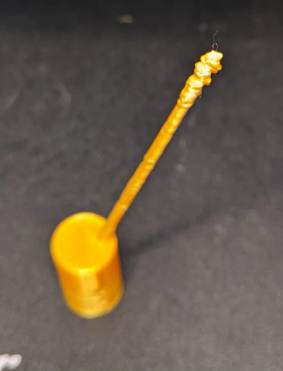
Thin Tall Part test
This was actually an inadvertent test piece. It was a small support for the test piece below. But it goes to shows a good example of one of the difficult parts to print, tall and skinny structures.
In this case, you can see that as the part gets near the top, the quality of the print goes down dramatically. In some prints, especially with materials that require a hotter extruder temperature (like ABS) it can be difficult to not allow too much heat to build up in a print, especially small objects that the print head is going over and over quickly.
We don’t believe this was the case here, but rather it is the height, plus the small structure that allowed this print to start swaying/bending as the print head tried to print too it. And as the material moved more, the quality greatly diminished. In fact, this could be in part fo the failure of the first print below.
The rod is 0.100” (2.5mm) in diameter and is 2.57” tall (65.3mm) when it broke.
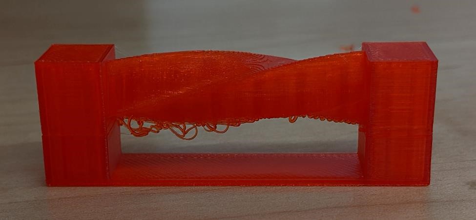
Wave Torture Test
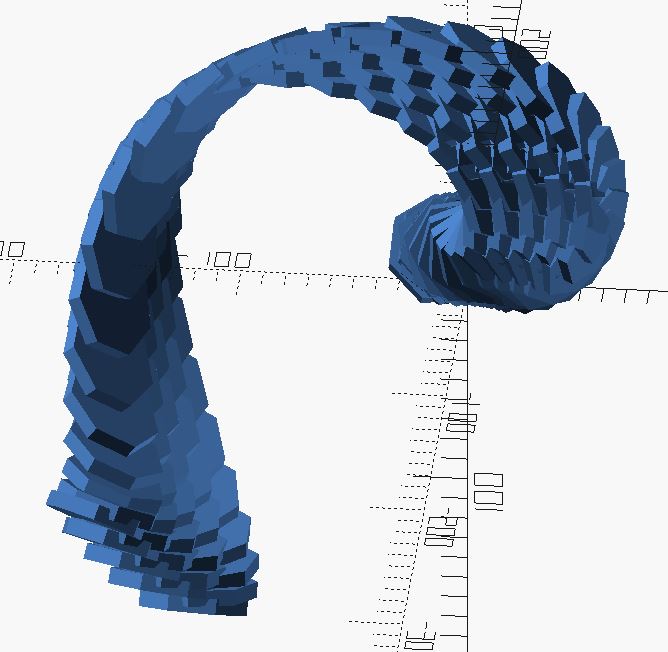
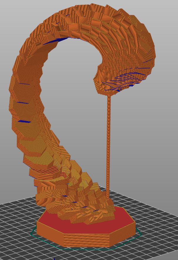
Since the above image was taken, Garrett added supports, as obviously part of the print would literally trying to print in air. However, I tried to minimize the amount of support and the support material (both for speed of print, as well as to test how well the printers handled this minimum amount of support and if they would be successful.)
These tests were printed on Garrett’s personal printer, a well used Ender 3 with eSun silky PLA filament. Sliced with Prusa Slicer. Layer height of 0.28mm, 2 side and top perimeters, 5% adaptive cubic infill.
At first, things went fine.
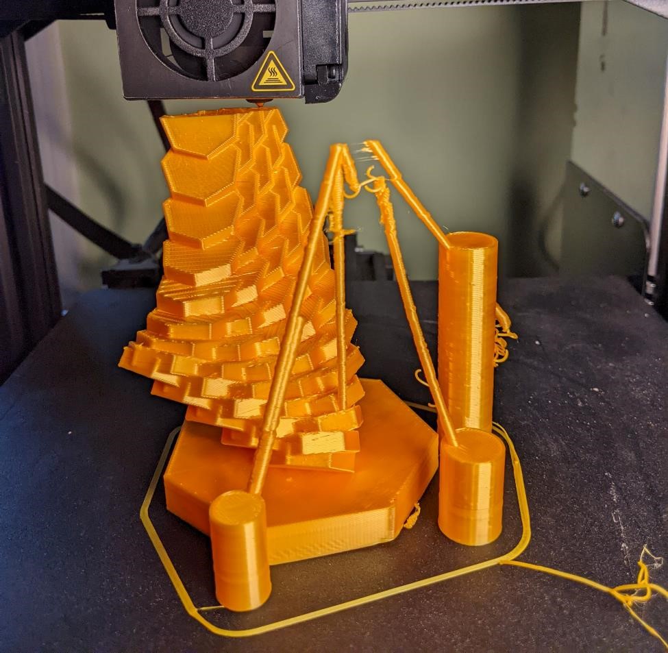
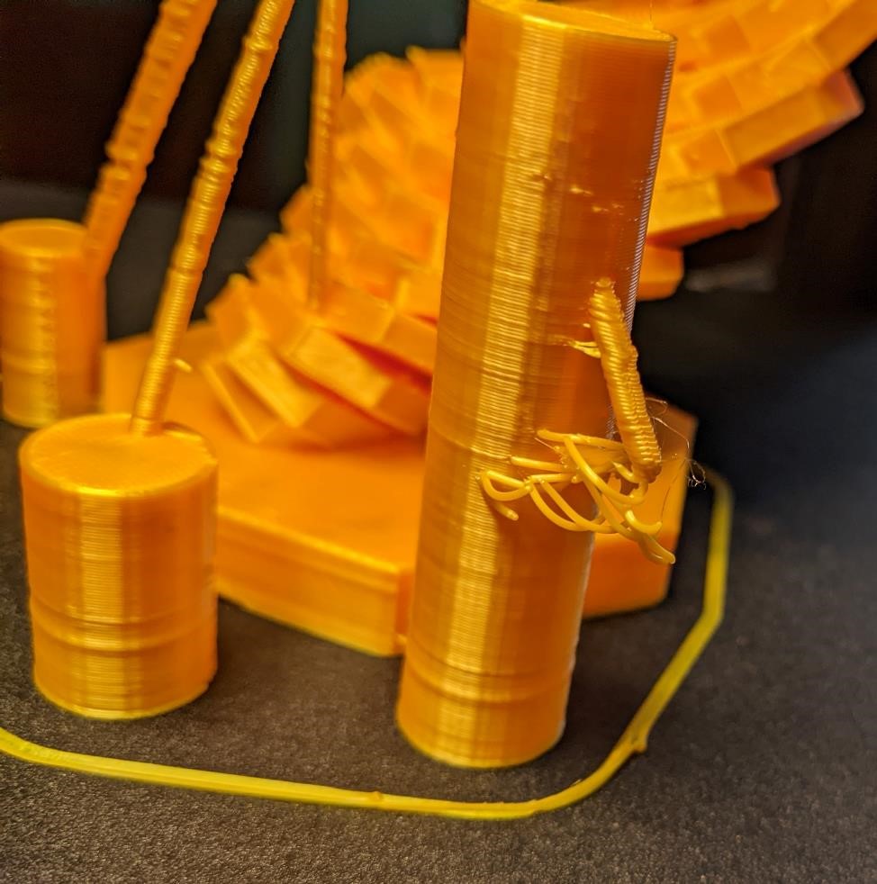
Though in the above photo, you can see that one of the support rods broke near the top. A sign of things to come.
And I found it interesting that a small support rod that I had intentionally left hanging in air managed to actually print halfway decent.
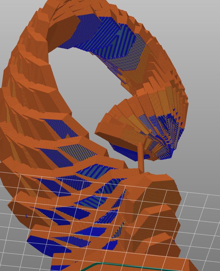
Disaster soon struck.
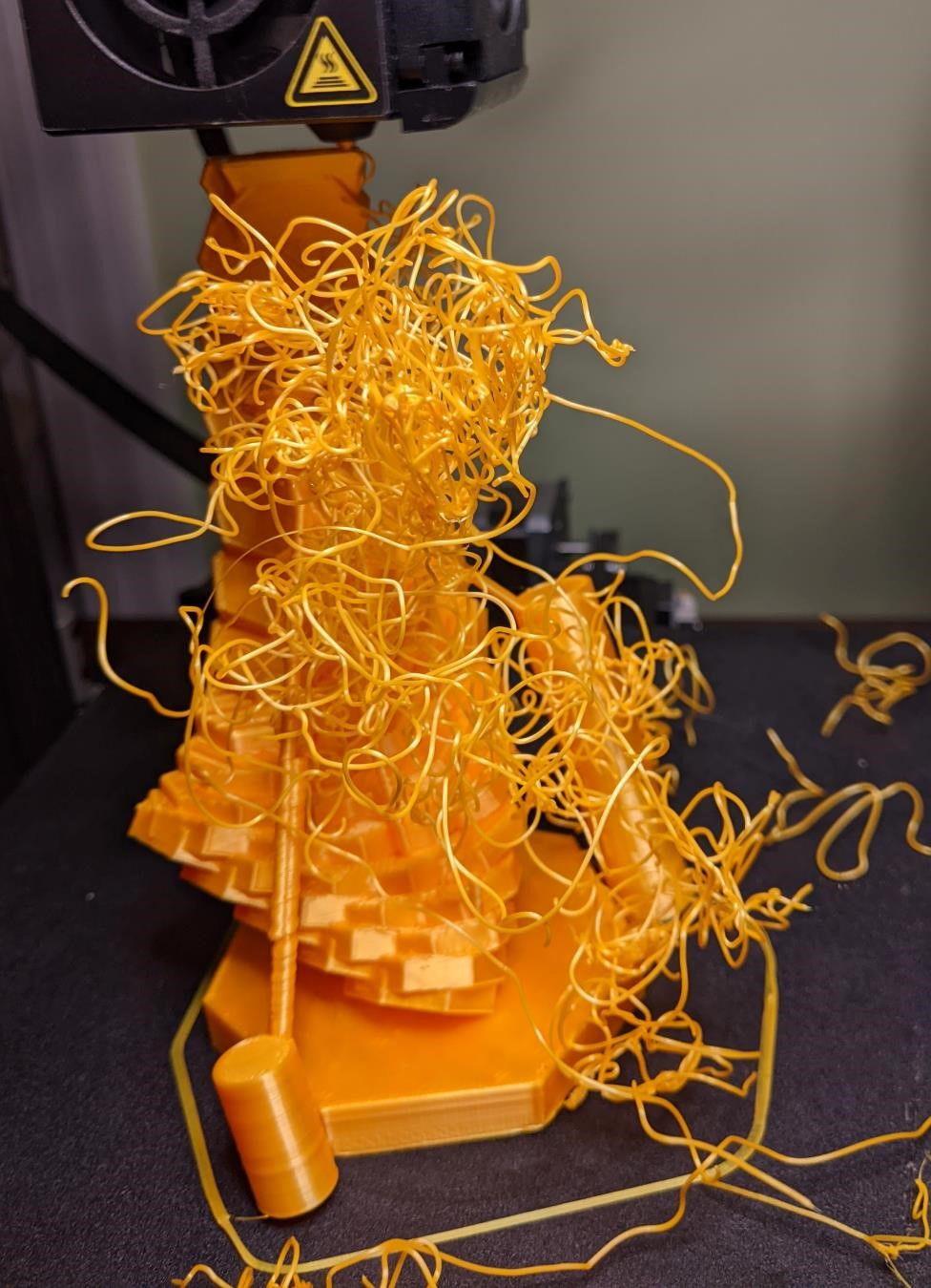
The small cylinders did not have enough adhesion to the bed, and it seems they broke off, leaving the top side of the wave trying to print in air. Garrett left the print going to see what the final outcome would be.
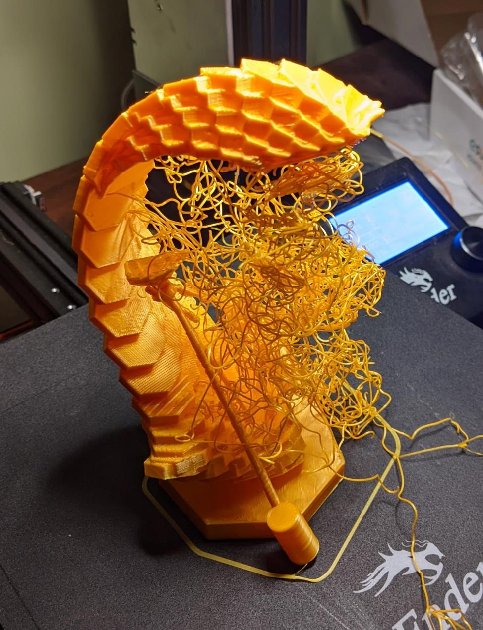
And he tried again. WIth a weird outcome, it seems there was a print shift at the top. Garrett’s not sure what happened…
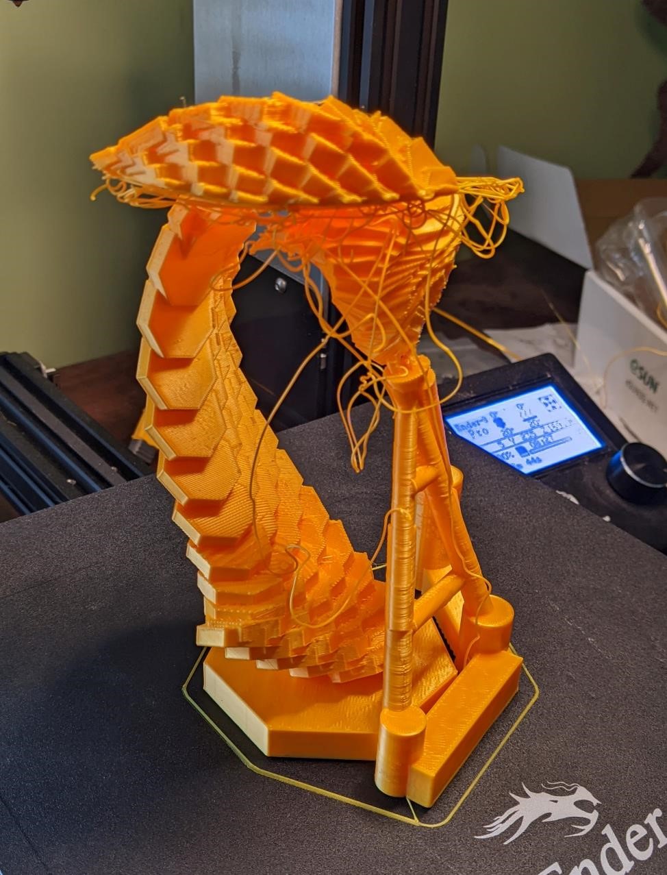
Two tries is enough. This print wasn’t supposed to be succesful. It was to test a FDM printer’s ability to print overhangs. The print wasn’t optimized for success. This was a good attempt, and shows that with a bit more work (read: just a bit of support), this is quite printable, and the ability of printers to handle large overhangs in the right circumstances.
//sgn wave feb 2022
//based off petals.scad designed for FabAcademy Cad week 2022

$fn = 32;

//to support the print and provide a base.
//BASE
translate([-120,-150,50])
rotate([-70,0,155])
cube([150,150,20], center = true);

//ROD
translate([-60,-60,52])
rotate([-70,0,155])
cylinder(d=5, h = 200, center = true);

dia = 50; //default: 100
thick = 7;  //default: 5
a = 6;  //default: 6
b = 3;  //default: 3
fins = 7; //default: 6
em = 4 ;  //petals per layer, default: 6
nn = 30; //layers of petals. default: 3

//scale - default 1
j = 1;  //x
f = 1;  //y
k = 1;  //z

//rotations
q = 14;  //default: 14
r = 7;  //default: 7
full_angle = 30; //default: 360
twist_twist = 0;


for(m = [0:em]){
scale([j,f,k])
rotate([0,0,m*full_angle/em])
translate([0,30,0])
for(n = [0:nn]){
rotate([n*q+14,0,n*r])
translate([n*a,n*b,n])
stand();
}
}


module stand(){
translate([0,0,0])
rotate([0,90,60])
linear_extrude(thick, center = true, convexity = 10, 30, slices = 400, twist = twist_twist, scale = 1.0, $fn = fins)
rotate([20,0,0])
circle(d = dia, $fn = fins);
//cylinder(d = 100, h = thick, center = true, $fn = fins);
//cube([100,5,100], center = true);


}
And that’s that. If you made it this far, congratulations.
Unfortunately, we did not receive access to a resin printer or the GOM scanner until the night before the Wednesday morning class. However, we would all like to use these two items more in the future.