13. Input Devices
April 20 2022
This week we’re connecting input devices to collect and interpret data.
Return of the Accelerometer Monster
(For more on this on going saga, see Week 7 and Week 9 )
I wasn’t able to get my ADXL343 boards to work originally. I traced one of the issues back to poor soldering. The other issue was a complete and total muckup of a board. I had switched the GND and 5v coming from the USB port. Yikes!
While an incredibly stupid mistake, I was able to fix it by replacing the fried 3.3v voltage regulator and cutting the USB traces and adding flying wires. Then I used a multimeter to check for shorts between the GND and 5v pins.
Even after fixing this issue, the board was still showing a short between GND and 5v. I examined the board for any poor solder joints, and obvious solder bridges, or other issues. I didn’t see anything and after consulting with Denny Leak, he suggested I isolate the accelerometer chip and see if the GND and 5v there were shorted. I did this and sure enough, there was my short. I removed the chip using a hot air station, and then resoldered in a new ADXL343 (just being careful, I was afraid I had fried the old one with the reversed polarity and the shorts.)
However, when I hooked these devices up, I was unable to get information from them.
Since then, I’ve reflowed the board yet one more time. It probably won’t work either. I’m going to try the oven for reflow soldering next (if I get time. unlikely. UPDATE: Nope, it shorted out again. So 6th time’s the charm?)
I came across a couple of issues.
Issue One
The device couldn’t be found.
I connected the ADXL343 accelerometer up to the SDA/SCL pins on my ATtiny412 board. However, when I tried to see if there were any i2c devices hooked up, I didn’t see any.
I had looked around and found this code to test with, the following code simply looks for the i2c address of any hardware hooked up. As the ADXl343 has an i2c address, it should be found.
Code from: https://create.arduino.cc/projecthub/abdularbi17/how-to-scan-i2c-address-in-arduino-eaadda
// Arduino I2C Scanner
// Re-writed by Arbi Abdul Jabbaar
// Using Arduino IDE 1.8.7
// Using GY-87 module for the target
// Tested on 10 September 2019
// This sketch tests the standard 7-bit addresses
// Devices with higher bit address might not be seen properly.


#include <Wire.h> //include Wire.h library

void setup()
{
  Wire.begin(); // Wire communication begin
  Serial.begin(9600); // The baudrate of Serial monitor is set in 9600
  while (!Serial); // Waiting for Serial Monitor
  Serial.println("\nI2C Scanner");
}

void loop()
{
  byte error, address; //variable for error and I2C address
  int nDevices;

  Serial.println("Scanning...");

  nDevices = 0;
  for (address = 1; address < 127; address++ )
  {
    // The i2c_scanner uses the return value of
    // the Write.endTransmisstion to see if
    // a device did acknowledge to the address.
    Wire.beginTransmission(address);
    error = Wire.endTransmission();

    if (error == 0)
    {
      Serial.print("I2C device found at address 0x");
      if (address < 16)
        Serial.print("0");
      Serial.print(address, HEX);
      Serial.println("  !");
      nDevices++;
    }
    else if (error == 4)
    {
      Serial.print("Unknown error at address 0x");
      if (address < 16)
        Serial.print("0");
      Serial.println(address, HEX);
    }
  }
  if (nDevices == 0)
    Serial.println("No I2C devices found\n");
  else
    Serial.println("done\n");

  delay(5000); // wait 5 seconds for the next I2C scan
}
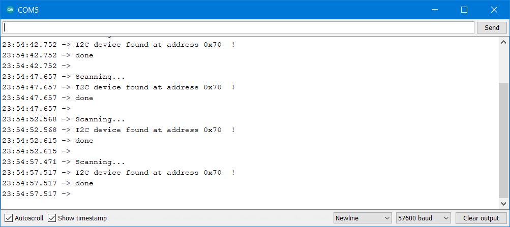
This did not find any i2c device.
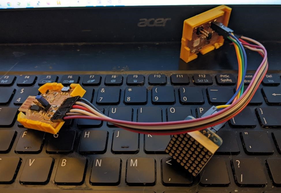
Being careful, I found an older 8x8 LED matrix display that used the i2c protocol, and hooked it up to see if it was discoverable. It was discoverable, and as such, I knew the issue wasn’t the software, or the board, but rather the ADXL343 chip.
Found a matrix display’s i2c address.
Oh well. I’ll try again another day.
Issue Two
No support for the libraries for Attiny412 or SAMD11C14.
The second issue was that there seemed to be no support for either the ATtiny412 or the SAMD11C14 through the normal, and well used Adafruit libraries for the ADXL343. Even if I were able to talk to the chip, I would have to write my own library to get the data off of it. No thank you.
(Note, I found out during the lecture, that Neil might have his own library to work with these. I’ll have to investigate further, but I’ll do so later once I actually get the i2c connection problems fixed.)
Moving on to Rotary Encoders
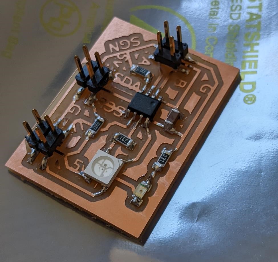
This was the board I’m using for this encoder project, an attin412 based board. (again, you can find this on Week 9.)
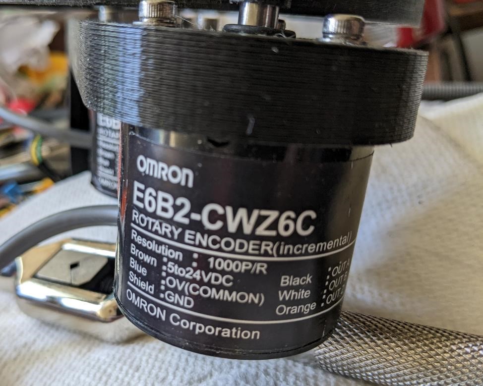
and the rotary encoder I used.
Setting up Rotary Encoders
Info on Attiny412 and Interrupts:
https://github.com/SpenceKonde/megaTinyCore/blob/master/megaavr/extras/Ref_PinInterrupts.md
and
https://github.com/SpenceKonde/megaTinyCore/blob/master/megaavr/extras/Ref_Interrupts.md
Preparing - UPDI and Serial
While this may seem an obvious thing, you need to remember if you’re using one of the UPDI programming boards, you’ll need to re-program it and re-wire it in order to use the serial connections for it.
So the first thing I did was to hook up the typical UPDI programmer to my board and program the ATtiny412 board. I then used a different programmer board (I’m starting to leave them in specific configurations, because it’s easier than reprogramming and rewiring them all the time.) and program it to receive and transmit serial data.
For Serial communications, the ATtiny412 serial pins are physical pins 4 (TX)(PA1) and 5 (RX)(PA2) (alternatively, 2 and 3 are a second set, supposedly, but I’m not sure how this works.) Make sure to connect the TX pin on the attiny412 to the RX pin on the programmer, and vice versa.
In order to get the Serial system set-up I first took my programer and flashed this code to it:
void setup() {

   SerialUSB.begin(0);   // prepare to use the USB serial pins of the samd11 chip
   Serial1.begin(57600, SERIAL_8N1); // Adjust baud rate and use SERIAL_8N1 for regular serial port usage. 8E2 for UPDI.
}

void loop() {
   if (SerialUSB.available()) {   // if the USB serial port is connected and working...
      Serial1.write((char) SerialUSB.read()); //Send stuff from Serial port to USB
   }
   if (Serial1.available()) {  /// if traditional serial port is connected and working...
      SerialUSB.write((char) Serial1.read()); //Send stuff from USB to serial port
   }
} //end loop
Note in the above code that the serial setting is for 8N1, which is different than the 8E2 you use for the JTAG programmer to program other programmers. I also have the baud rate set to 56000.
After this, I connect the pins to my Attiny412.
I connect physical pin 4 (TX) to the RX pin of the programmer and Pin 5 (RX) to the TX pin of the programmer. I then connect GND and 5v from the attiny412 to the programmer. You can also leave the jumper for programmming UPDI on the programmer.
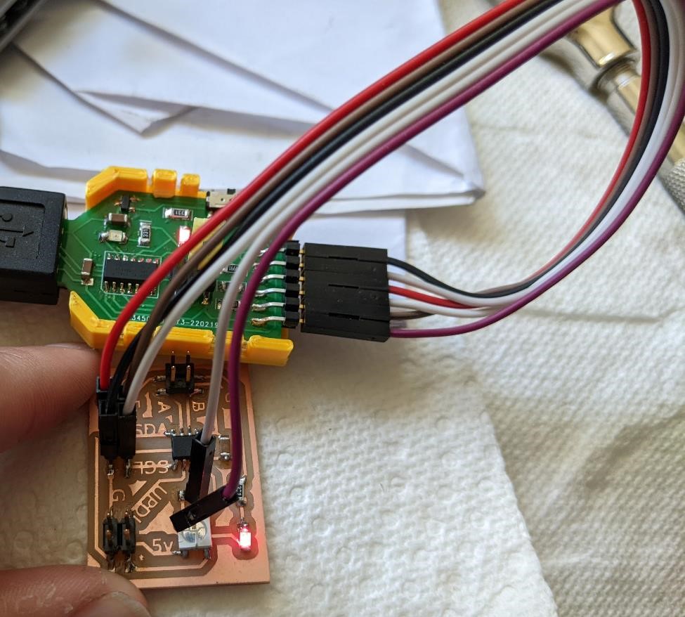
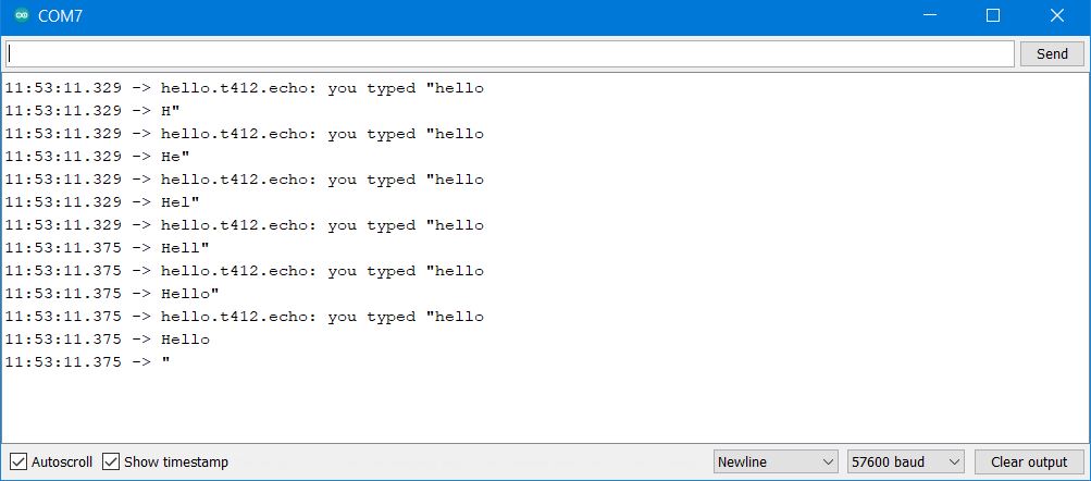
Once I did this, I tested to make sure this could transmit serial data by using the echo program.
//
// hello.t412.echo.ino
//
// tiny412 echo hello-world
//    115200 baud
//
// Neil Gershenfeld 12/8/19
//
// This work may be reproduced, modified, distributed,
// performed, and displayed for any purpose, but must
// acknowledge this project. Copyright is retained and
// must be preserved. The work is provided as is; no
// warranty is provided, and users accept all liability.
//

#define max_buffer 25

static int index = 0;
static char chr;
static char buffer[max_buffer] = {0};

void setup() {
   Serial.swap(1);
   Serial.begin(57600);
   }

void loop() {
   if (Serial.available() > 0) {
      chr = Serial.read();
      Serial.print("hello.t412.echo: you typed \"");
      buffer[index++] = chr;
      if (index == (max_buffer-1))
         index = 0;
      Serial.print(buffer);
      Serial.println("\"");
      }
   }
And after a bit of fiddling with the wires, I got it all to work.
Also note the above uses “Serial.swap(1);” in the setup section.
Again, make sure you have the same Baud Rates for:
- Your board that sends the data
- Your programmer that receives the data and forwards it to the computer
- Your Serial Monitor on Arduino.
Reprogramming Again
Next, after I’ve tested the serial connections, I’m going to reprogram the attiny board to capture data from the rotary encoder and spit out the numbers on the serial monitor.
I hook up another UPDI programming board and program it with the following code:
volatile long temp, counter = 0; //This variable will increase or decrease depending on the rotation of encoder

const byte pinA = 0;   // for pin A of encoder
const byte pinB = 1;   // for pin B of encoder

void setup() {
  Serial.begin (57600);  // start serial port with baudrate 57600

  pinMode(pinA, INPUT_PULLUP); // internal pullup input pin

  pinMode(pinB, INPUT_PULLUP); // internal pullup input pin

   //Setting up interrupt
  //A rising pulse from encodenren activated ai0(). AttachInterrupt 0 is DigitalPin nr 2 on moust Arduino.
  attachInterrupt(digitalPinToInterrupt(pinA), ai0, RISING);

  //B rising pulse from encodenren activated ai1(). AttachInterrupt 1 is DigitalPin nr 3 on moust Arduino.
    attachInterrupt(digitalPinToInterrupt(pinB), ai1, RISING);
  }

  void loop() {
  // Send the value of counter
  if( counter != temp ){     // if the counter isn't the same as last time...
  Serial.println (counter);   // print out the new value of encoder
  temp = counter;            // set the two values the same, so that we can check it as it loops
  }
  }

  void ai0() {
  // ai0 is activated if DigitalPin nr 2 is going from LOW to HIGH
  // Check pin 3 to determine the direction
  if(digitalRead(pinA)==LOW) {
  counter++;    // increment the counter by adding 1
  }else{
  counter--;     // decrease the counter by subtracting 1
  }
  }

  void ai1() {
  // ai0 is activated if DigitalPin nr 3 is going from LOW to HIGH
  // Check with pin 2 to determine the direction
  if(digitalRead(pinB)==LOW) {
  counter--;
  }else{
  counter++;
  }
  }
(I’m not going to lie, the whole switching programmers and cables constantly is rather annoying.)
Let’s connect the rotary encoder
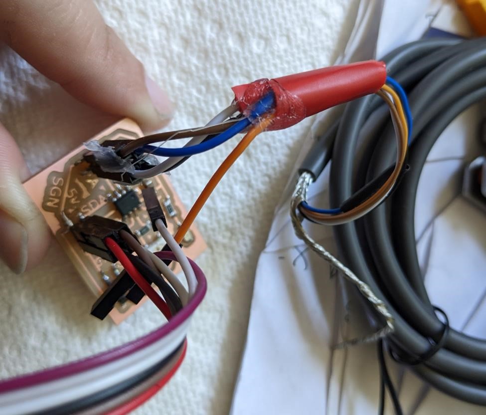
Next I’m going to connect the quadrature incremental rotary encoder. This has 4 pins, and being quadrature, it means that it has two pins that each produce a signal, indicating it has moved. Between these two signals, you can better note which direction the encoder is turning. It also has two lines for power and ground.
I’m connecting the rotary encoder A and B data lines to physical pins 2 and 3 of the attiny.
For more on Quadrature encoders, see:
https://www.rs-online.com/designspark/quadrature-encoder-basics-part-1-theory
https://cdn.sparkfun.com/datasheets/Robotics/How%20to%20use%20a%20quadrature%20encoder.pdf
and Adam just showed me about this: https://hackaday.com/2022/04/20/a-rotary-encoder-how-hard-can-it-be/ with some help with using the encoders (see comments for more information.)
I then used this code:
volatile long temp, counter = 0; //This variable will increase or decrease depending on the rotation of encoder

const byte pinA = 0;
const byte pinB = 1;

void setup() {
  Serial.begin (57600);

  pinMode(pinA, INPUT_PULLUP); // internal pullup input pin 2

  pinMode(pinB, INPUT_PULLUP); // internalเป็น pullup input pin 3
   //Setting up interrupt
  //A rising pulse from encodenren activated ai0(). AttachInterrupt 0 is DigitalPin nr 2 on moust Arduino.
  attachInterrupt(digitalPintoInterrupt(pinA), ai0, CHANGE);

  //B rising pulse from encodenren activated ai1(). AttachInterrupt 1 is DigitalPin nr 3 on moust Arduino.
    attachInterrupt(digitalPintoInterrupt(pinB), ai1, CHANGE);
  }

  void loop() {
  // Send the value of counter
  if( counter != temp ){
  Serial.println (counter);
  temp = counter;
  }
  }

  void ai0() {
  // ai0 is activated if DigitalPin nr 2 is going from LOW to HIGH
  // Check pin 3 to determine the direction
  if(digitalRead(pinA)==LOW) {
  counter++;
  }else{
  counter--;
  }
  }

  void ai1() {
  // ai0 is activated if DigitalPin nr 3 is going from LOW to HIGH
  // Check with pin 2 to determine the direction
  if(digitalRead(pinB)==LOW) {
  counter--;
  }else{
  counter++;
  }
  }
And nothing happened. I tried changing pins, and a number of other things. I checked cables, re-checked to make sure I could read the serial data. And yet I received zero data from the Rotary Encoders. I have no idea what’s going on. My hunch is that it has something to do with the interrupt process on the Attiny412.
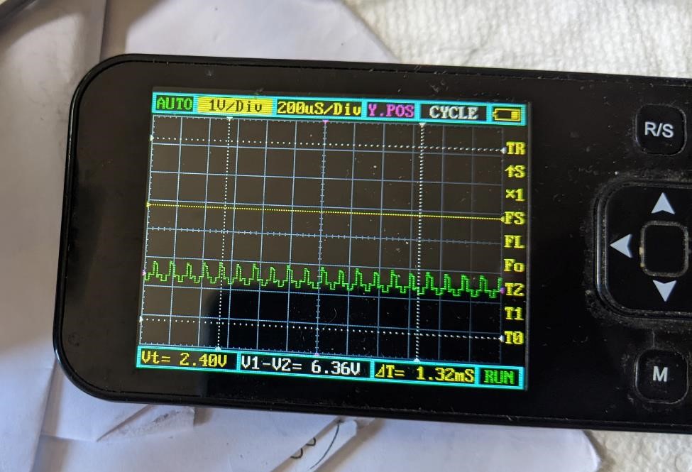
I checked the power with a multimeter, and it was reading 5.1v. I hooked the power up to the rotary encoder, and then used an oscilloscope to the A and B pins of the rotary encoder, and you could see the pulses coming from the rotary encoder. However, I will say they did appear to be rather weak, only having about a 1v peak to peak signal.
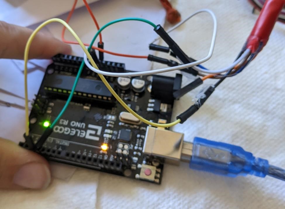
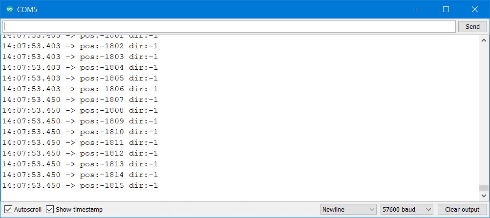
I also used an Arduino with almost the exact same code, and it read the rotary encoders and output data.
And I get the expected results:
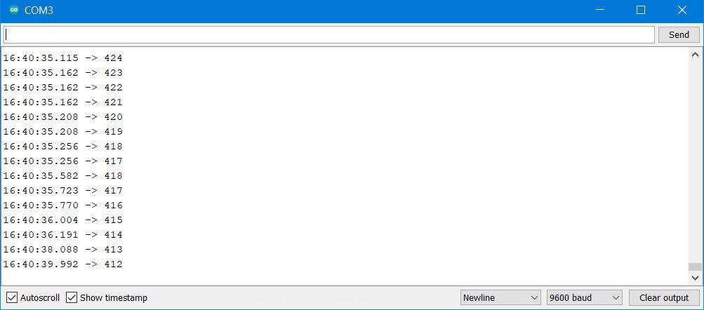
I also used an oscilloscope and checked to see if the roatery encoder was putting out data, while a bit weaker than I would have expected, it was working.
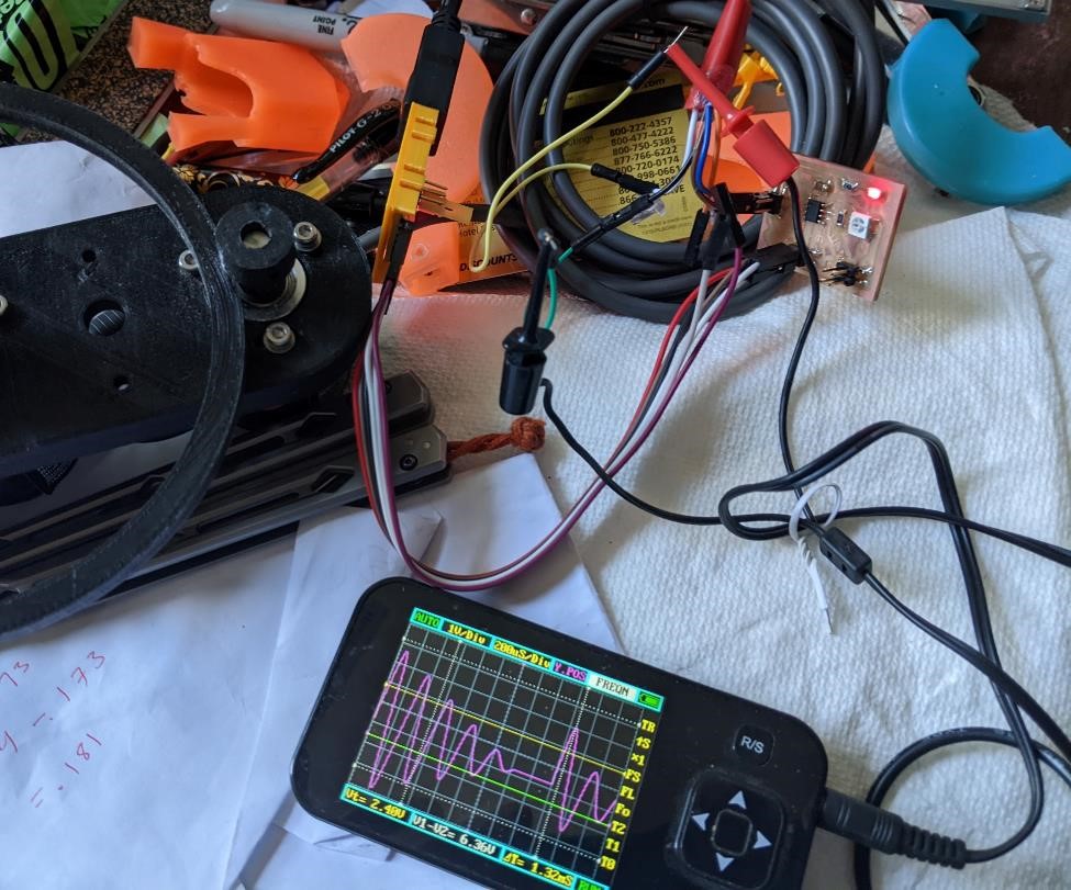
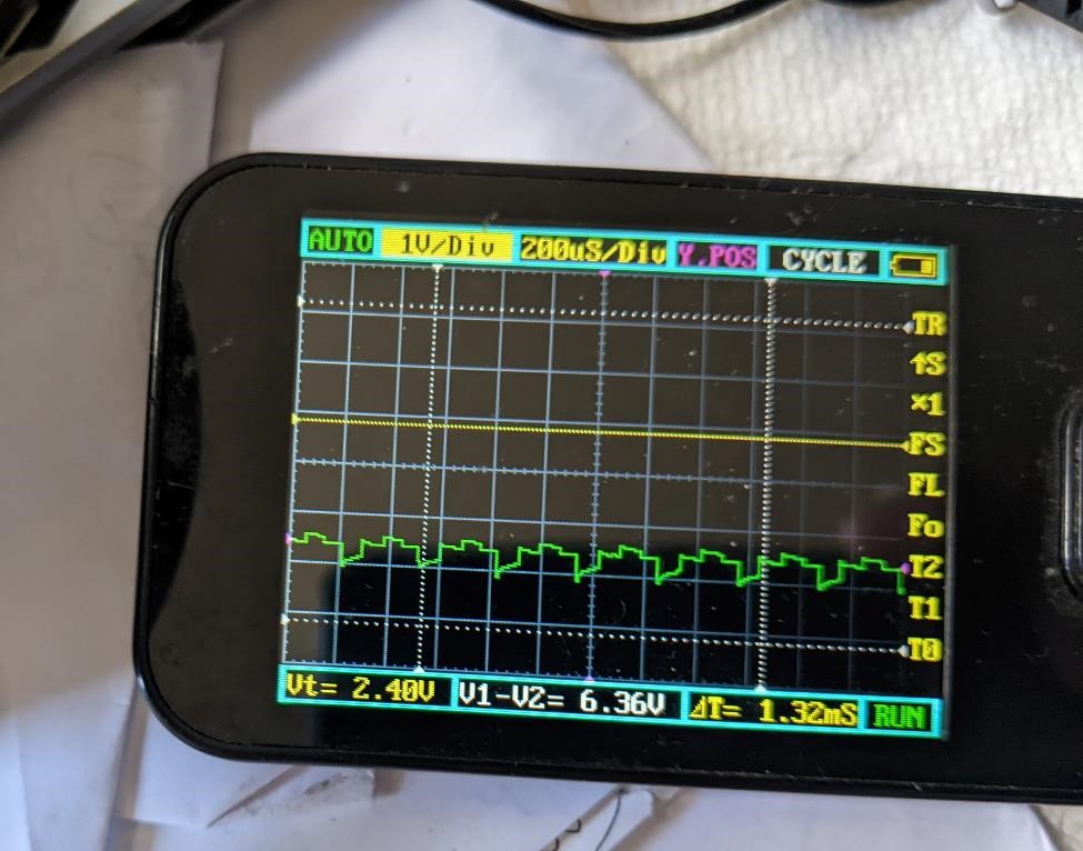
And when you power up the encoder, you can see the output:
Low signal
I noticed something about this output (it’s the green line, ignore the purple line, it’s just a stupid background image.) The output is very weak. Even though it was read by the Arduino (runnin at 5v, with the encoder running at 5v.) The signal is less than 1v peak to peak (p-to-p)
I asked Denny about this and he asked me about the data sheet for this encoder. I had origninally looked on the Omron website for this, but I did not find one. We went back, and somewhat hidden away, we found the technical documentation talking about output signals.
(The PDF document is here: https://www.ia.omron.com/data_pdf/guide/34/rotary_tg_e_7_2.pdf )
And the Specifications of the encoders (https://www.ia.omron.com/products/family/487/specification.html)
And according to the spec’s, it’s a “NPN Open-collector output.” (https://learn.adafruit.com/transistors-101/open-collector)
Which apparently, according to Denny explains why the output signal was so low. And an easy way to fix this is to simply provide a pull-up resistor (1k may be enough) and this will improve the signal output.
We thought this was a great lesson, even if your system is working, hooking it up to a type of signal analyzer gives more information on your electronics. Just using an oscope to look at our encoder showed us that something was slightly off, and even though Garrett and Cori didn’t understand what was going on with this, we understood something was off and we were able to consult an expert (Denny) for more information on how to fix this issue.
Yet Another New Board - Attiny412
I’ve come back and created yet another board based on the Attiny412, carrying a neopixel board. This board keeps growing. First I had forgotten to add pullup resistors for SCL/SDA. Now I’ve added pullup resistors for the encoder/input hookups. 1k for position “A” and position “B” (physical pins 2 and 3).
![]()
![]()
I’ve yet to actually make this board, but hopefully I’ll get a chance in the next few days.
Interrupts
I fiddled around with this code: https://github.com/SpenceKonde/megaTinyCore/blob/master/megaavr/extras/Ref_PinInterrupts.md
FYI: ISR is “Interrupt Servicing Routine”
But that wasn’t very successful, I either got a constant “interrupt triggered” or nothing. But again, this gave me a hint at where the issue lay.
I wanted to try using the SAMD11C chip for this, but as it is based off of 3.3v system, and the rotary encoder needs 3.3v volts (I even tested this, and I wasn’t able to get anything out of the encoder at 3.3v), I’d have to have a system for changing logic levels, I didn’t have access to this when I was working on it. (update: because of the open collector system, I should be able to read this encoder with a pullup resistors and 5v supplied to the encoder, and 3.3v to the samd11.)
I would like to point out how stupid this whole process is. I’m trying to reinvent the wheel on a microprocessor that I know nothing about. Dumb. I’ve got a tool (arduino) that works, but noooo… you’ve got to become an expert in microprocessors and interrupts. For me, that’s not happening in a week. This is yet another exercise in frustration for zero purpose.
Update, got it to semi-work, poorly with polling.
I did try simple polling, but the faster you turn the encoder, the slower it actually shows you’re moving. There’s either a polling issue (it’s dropping signals) or something else. But it’s not useful.
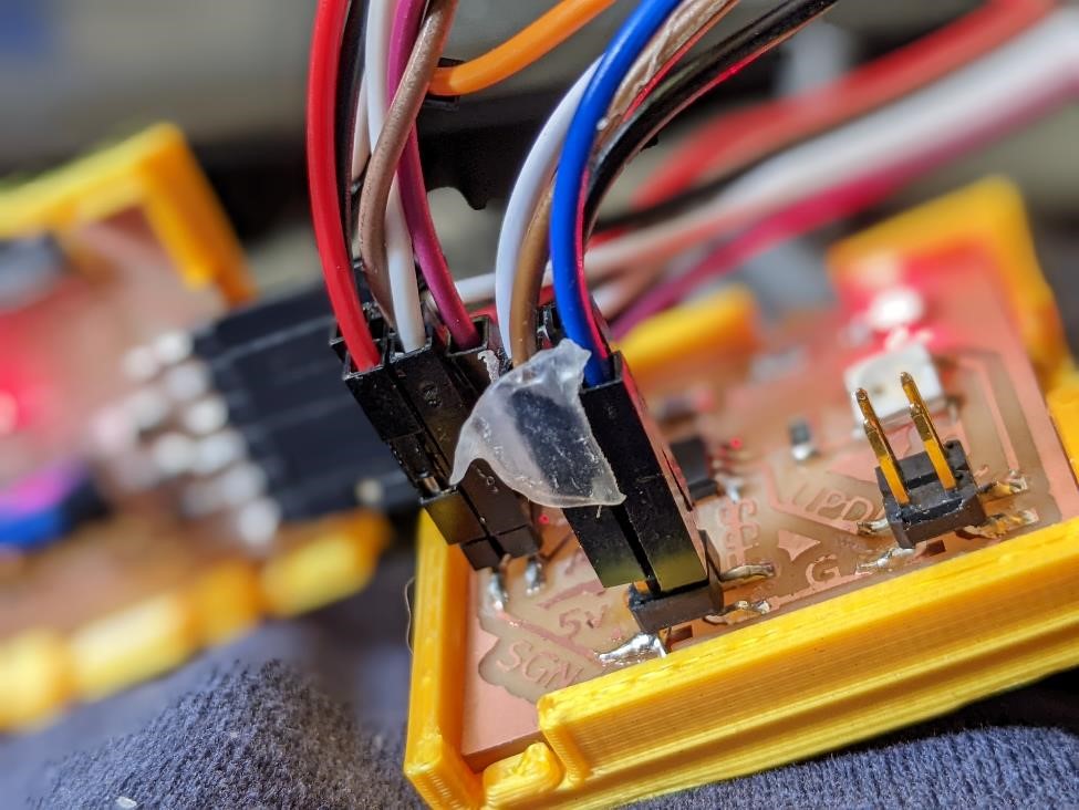
Let’s try something else
DHT22 sensor

I used this library from Adafruit designed specificially for Attiny85 processors. TinyDHT
I’m not even going to bother documenting most of this. I tried 100 things, nothing worked.
I had issues with the serial port, fixed that, and then it simply couldn’t read the sensor. I only have one sensor, so I can’t determine if the sensor is bad, or I just can’t properly get the data off.
I managed to get some rather spurious data at one time.
This was the code that got me closest:
// Example testing sketch for various DHT humidity/temperature sensors
// Written by ladyada, modified for integer use, public domain

#include "TinyDHT.h"

#define DHTPIN 0    // DHT connected to Arduino Uno Digital Pin 2

// Uncomment whatever type you're using!
//#define DHTTYPE DHT11   // DHT 11
#define DHTTYPE DHT22   // DHT 22  (AM2302)
//#define DHTTYPE DHT21   // DHT 21 (AM2301)


// Connect pin 1 (on the left) of the sensor to +5V
// Connect pin 2 of the sensor to whatever your DHTPIN is
// Connect pin 4 (on the right) of the sensor to GROUND
// Connect a 10K resistor from pin 2 (data) to pin 1 (power)
//    of the sensor

DHT dht(DHTPIN, DHTTYPE);

void setup() {
  Serial.swap(1);  //attiny412
  Serial.begin(57600); // Output status on Uno serial monitor
  Serial.println("DHTxx test!");

  dht.begin();
}

void loop() {
  // Reading temperature or humidity takes about 250 milliseconds!
  // Sensor readings may also be up to 2 seconds 'old' (its a very slow sensor)
  int8_t h = dht.readHumidity();
  int16_t t = dht.readTemperature(1);

  // check if returns are valid then something went wrong!
  if ( t == BAD_TEMP || h == BAD_HUM ) { // if error conditions
    Serial.println("Failed to read from DHT");
  } else {
    Serial.print("Humidity: ");
    Serial.print(h);
    Serial.print(" %\t");
    Serial.print("Temperature: ");
    Serial.print(t);
    Serial.println(" *C");
  }
  delay(2000);
}
I tried different libraries, I tried the SAMD11C14 chip. (I’ve come to learn, that with the arduino bootloader, this chip is virtually useless. The storage space is nil. There’s no room for even small libraries on it. It may be powerful, but unless you can program it without the use of the arduino bootloader, it can’t be used for much.)
Very few libraries support the Attiny412, so that also left me without many options.
I tried so many different libraries, nothing worked.
I’m giving up. I don’t care what the temperature is anyways. If I’m cold, I put on a coat.
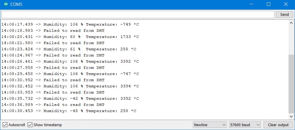
Hall Effect Sensor
I found a hall effect sensor in my extra electronics bin, I had no idea what it was, other than I could see “44e 402” on it. I googled and came across this video: https://www.youtube.com/watch?v=4eqi0G7uY_4 which gave me some good information. From here I was able to get the sensor to work in a digital “on” or “off” mode. I was curious about getting analog signals out of it, but I think this is a digital only sensor, but I’ll double check.
This too used the simple Attiny412 board I’ve been using.
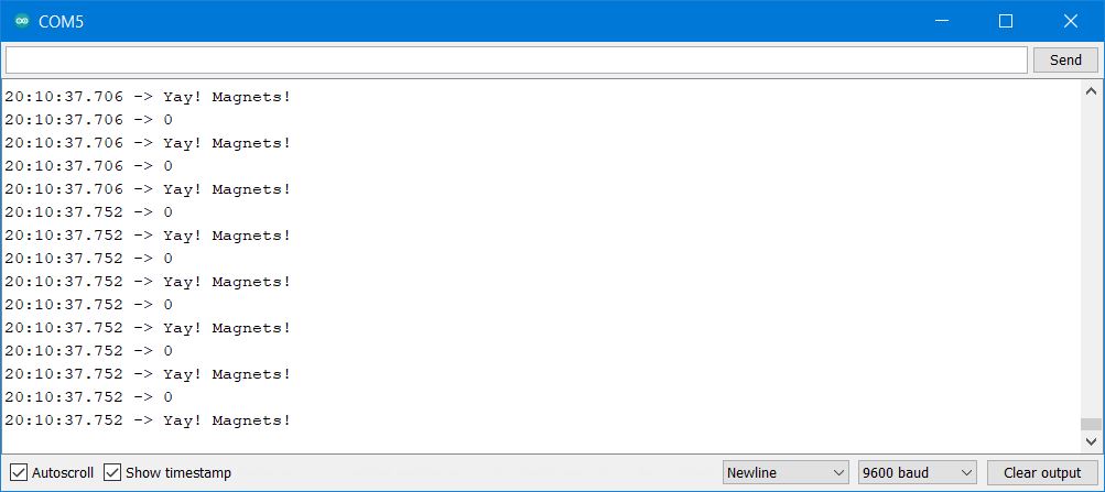
The below code works as a digital sensor for magnetic fields. In prints a “0” when it senses a magnetic field, and a “1” when it doesn’t (yes, it’s backwards; no, I don’t care.)
int HallSensorPin = 0;   // pin assignment, physical pin 2 on attiny412


int state = 0;           // is the sensor triggered or not?


void setup() {
  Serial.swap(1); //for attiny412 alternative serial interface
  Serial.begin(57600);  // turn on serial port, 57600 baud
  pinMode(HallSensorPin, INPUT); // prepare this pin to receive data


}

void loop() {

   //state = analogRead(HallSensorPin);   // early try at reading analog
    state = digitalRead(HallSensorPin);   // let's read digital instead...
   Serial.println(state);                 // print over serial the state (on or off)
   Serial.println();                      // prints a line break for readability.
   delay(100);                            // wait 100 microseconds
}
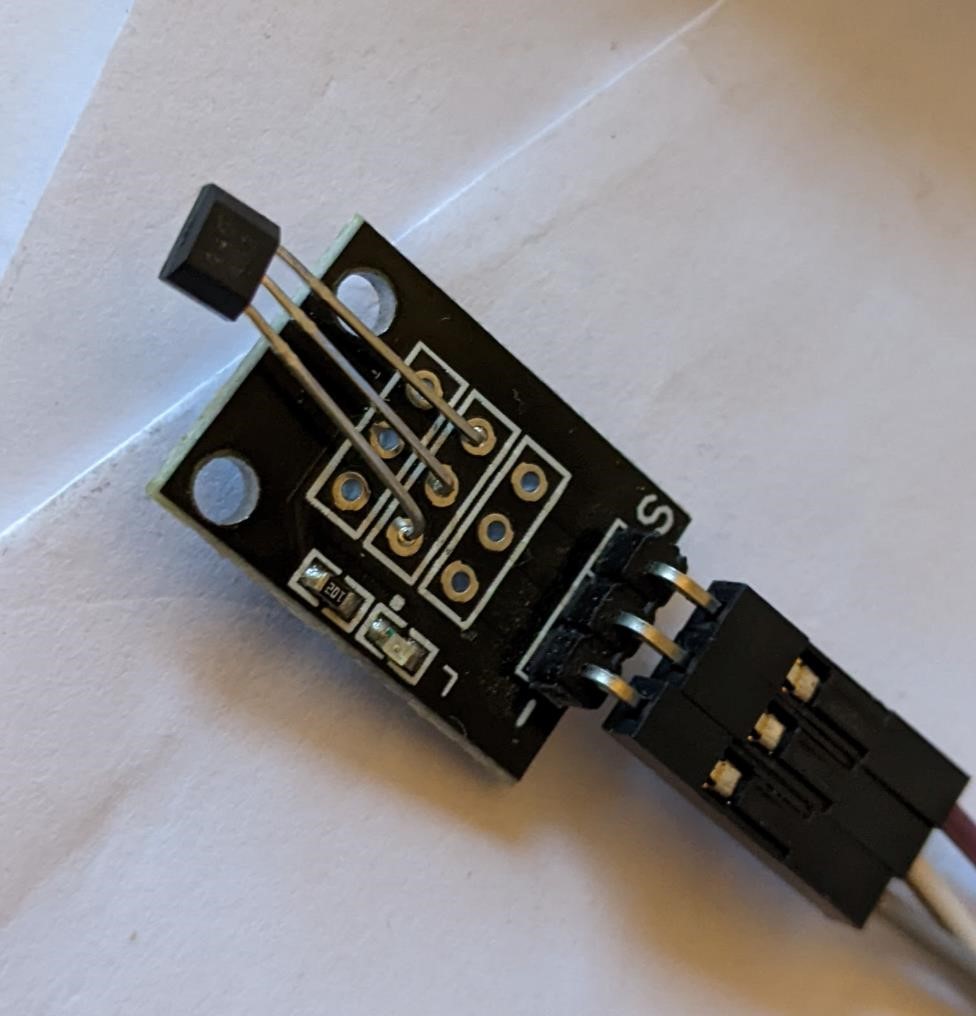
And then I added a neopixel to the process, that will turn green if it senses a magnetic field, or else it will stay red.
And when it works:
#include <tinyNeoPixel.h>    // include the neopixel library to get them to work.

int HallSensorPin = 0;     // pin assignment, physical pin 2 on attiny412
int neoPin = 4;            // pin on attiny412 neopixel is connected too (phys pin 7)
int NUMPIXELS = 1;         // we just have 1 neopixel on this board

int state = 0;             // variable to keep track of if sensor triggered or not


// the below prepares the neopixels.  We tell it how many neopixels, what pin they're
// connected too.  What format LED's they use and how fast they are (these are based on
// the specific neopixels you use.)
tinyNeoPixel pixels(NUMPIXELS, neoPin, NEO_GRB + NEO_KHZ800);

void setup() {                    // prepare the program.
  Serial.swap(1);                 // for attiny412 alternative serial interface
  Serial.begin(57600);            // turn on serial port, baudrate of 57600
  pinMode(HallSensorPin, INPUT);  // turn on hall effect sensor pin, prepare for input
  pixels.begin();                 // INITIALIZE NeoPixel strip object (REQUIRED)
  pixels.setBrightness(35);       // about 1/3 brightness
  pixels.clear();                 // clear's pixel data.
}

void loop() {

   //state = analogRead(HallSensorPin);  // early try at reading analog
   state = digitalRead(HallSensorPin);   // read digital pin
   Serial.println(state);                // print the state to serial monitor
   if (state == 0){                      // if state = 0...
     Serial.println("Yay! Magnets!");    // "Yay, it worked!" Turn on neopixel
     pixels.setPixelColor(0, pixels.Color(0, 150, 0)); //green
     pixels.show();   // Send the updated pixel colors to the hardware.
   }
   else {                                // "boo, no magnets." I'm red and angry.
     pixels.setPixelColor(0, pixels.Color(150, 0, 0));  //red
     pixels.show();   // Send the updated pixel colors to the hardware.
   }
   delay(10); // a bit of a break
}
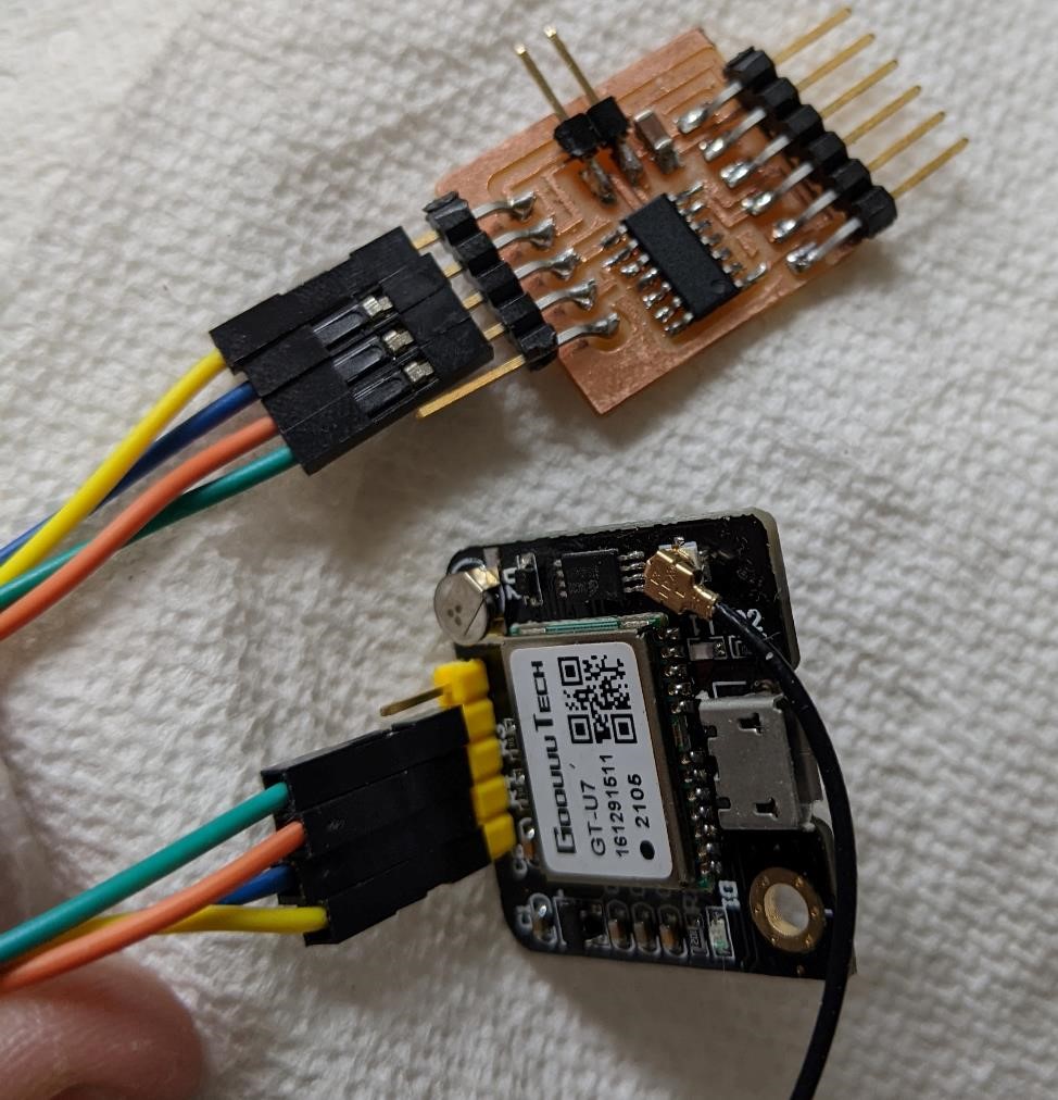
Even tried an attiny1614 and GPS
I made Neil’s ATtiny1614 and GPS module board, but I was never able to actually get it to work. I believe it was a serial problem. Ran out of time, but I want to get this one to work, so I’m hoping I can come back to it later.
This week was almost a complete failure.
Thankfully I found a digital hall effect sensor. I’m still disappointed I couldn’t get the rotary encoder to work. This is a key component of my final project, so that’s going to be an issue that I’ll have to fix.
I have two possible solutions:
1: Use a different board, such as an arduino based board. There will be compromises with this design. I may try using a samd11, and I think I can have it setup to use a 5v power supply and power a 3.3v logic system. This may be a good solution in the end, but I’ll have to get a better understanding of what’s going on in relation to power/logic levels before going this route.
2: Don’t focus on using interrupts, but rather focus on polling (polling is simply asking the sensor for it’s state, as quick as it can in a loop. Polling may miss information if the processor can’t keep up, and that’s why you would typically use an interrupt based system.)
Still trying to decide which to use.
Group Project
Group Project can be found here: Week 13 Group Project
I helped with designing the board we used for the group project, as well as working on finding different sensors to use to measure this part.
We settled on using my rotary encoders, because it was simple to hook up, and we thought it’d be interesting to see what the readings were, as they would be quadrature, and if they would be a constant pulse width (with different frequencies) or if there was obvious variations. We noticed obvious variations, but this could be due the slow readings of the oscilloscope that we used, or other unknown factors. (frankly, we don’t know enough at this time. We’ll have to consult more with Denny and Adam.)
We also discovered that the readings were very low, and that they probably needed a pull up resistor for the low voltage readings (see above “Low Signal” section for more information about this.)
But it was some neat information, and an interesting look at what quadrature encoders data actually looks like when in use.
References
As always, a number of references are posted throughout the above document.
https://www.rahulsrajan.com/arduino-147324
Files
As always, the code is posted above, and the board files can be found in Week 7 and Week 9