6. 3D Scanning and printing
Week 5 - 2/23/22
The homework is to make something that is not easily machinable.
Okay. Done.
The Design
a 2” x 2” x 2” cube.
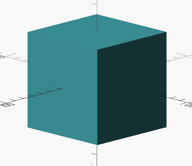
OpenSCAD code
//sgn feb 2022
//"Print something you can't machine."

$fn = 64;

difference(){
cube([50.4, 50.4, 50.4], center = true);

sphere(d = 38.1);
}
Please Explain.
Are you some type of smart ass? Yes.
But I can say with confidence that this would be impossible to machine.
While this is completely tongue-in-cheeck snarky, there is a reason I chose this design. I’m not a designer, I’m not an engineer, I’m not a programmer, so I can’t design some amazingly intricate piece of art or mechanism. But I have some idea about how things are built. And in this case, it’s not the outside shape that I’m interested in, but rather the internal structure.
Traditional subtractive manufacturing makes it difficult to add internal structures. 3d printing, more so than any other manufacturing technology, allows for this ability. Outside of the rapid prototyping, amazing freedom of design, and the democratization of production that 3d printing allows for, the ability to internally design structures is one of the most interesting parts of 3d printing to me.
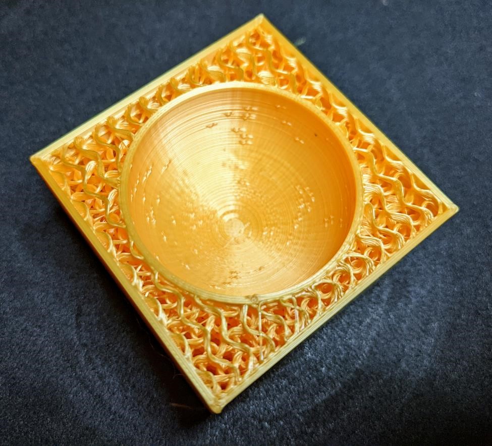
So let’s take a closer look at this cube.
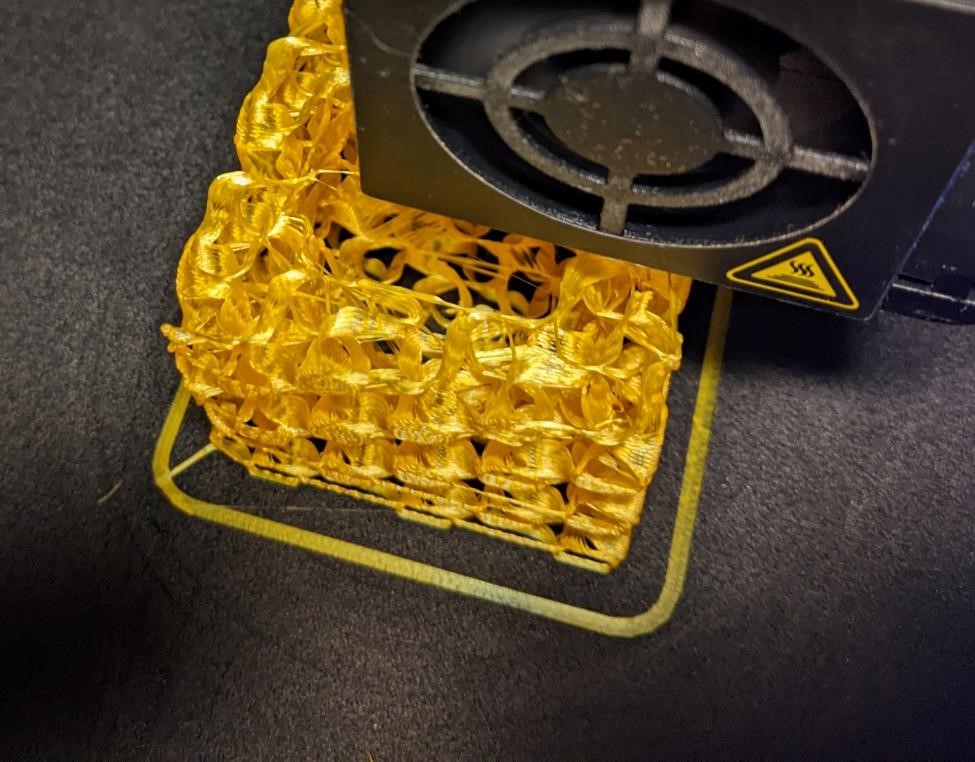
When you open up the above cube, this is the structure you will find inside:
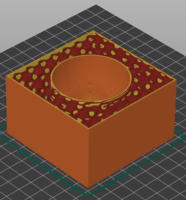
What we see here is that the cube is neither solid nor hollow. There is a 1.5” diameter sphere embededded inside the center of the cube. Between the sphere and the cube walls is a gyroid fill pattern. These two features will allow for an overall lighter part, but also maintaining strength of the overall part.
The other aspect of this design that I find interesting is the ease of designing it.
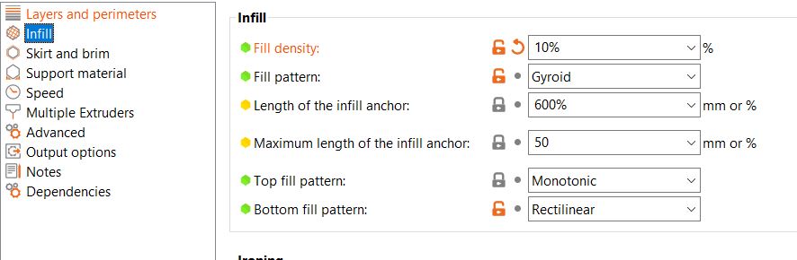
Creating a cube shape with a sphere inside was incredibly simple with OpenSCAD. But this is just a sphere inside a hollow cube. It’s the computation and science behind the Prusa Slicer that makes this truly interesting part. The Prusa Slicer allows me to choose my infill material, and I could use “gyroid” that would do all the infill automatically for me. With just two rather easy software applications, I could design what is rather a complex internal structure.
Using Prusa Slicer to set the gyroid 10% infill. Print time 2:35.
This is the easiest way to print just a gyroid: https://www.reddit.com/r/3Dprinting/comments/dwtavv/printed_a_2_cube_with_gyroid_infill_10_density/
While these structures may not serve much purpose for a plastic printed part on a consumer printer, they become more more interesting when printed on an industrial grade metal printer.
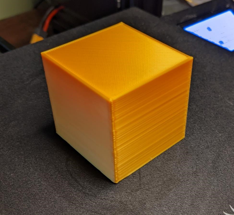
This cube may not be sexy. But I think it’s pretty damn neat.
And if that’s not somehow “cool” enough for you, go look through my CAD week or the “Wave” design in the group project for other parts that would be very difficult to manufacture traditionally.
The Prints

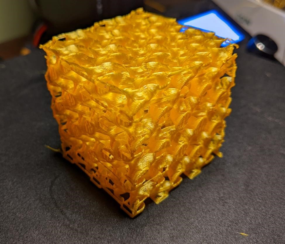
(the above is actually infill at 5% in order to provide a better visual example of gyroid infill.)
And that’s that. I don’t think something has to be complicated or complex to be beautiful. I don’t think something has to be over-engineered to be an amazing design. On the surface, it’s a simple cube, but it’s beauty is on the inside.
The 3mf file
THe 3mf files to recreate this 3d print can be found here
3d Scanning
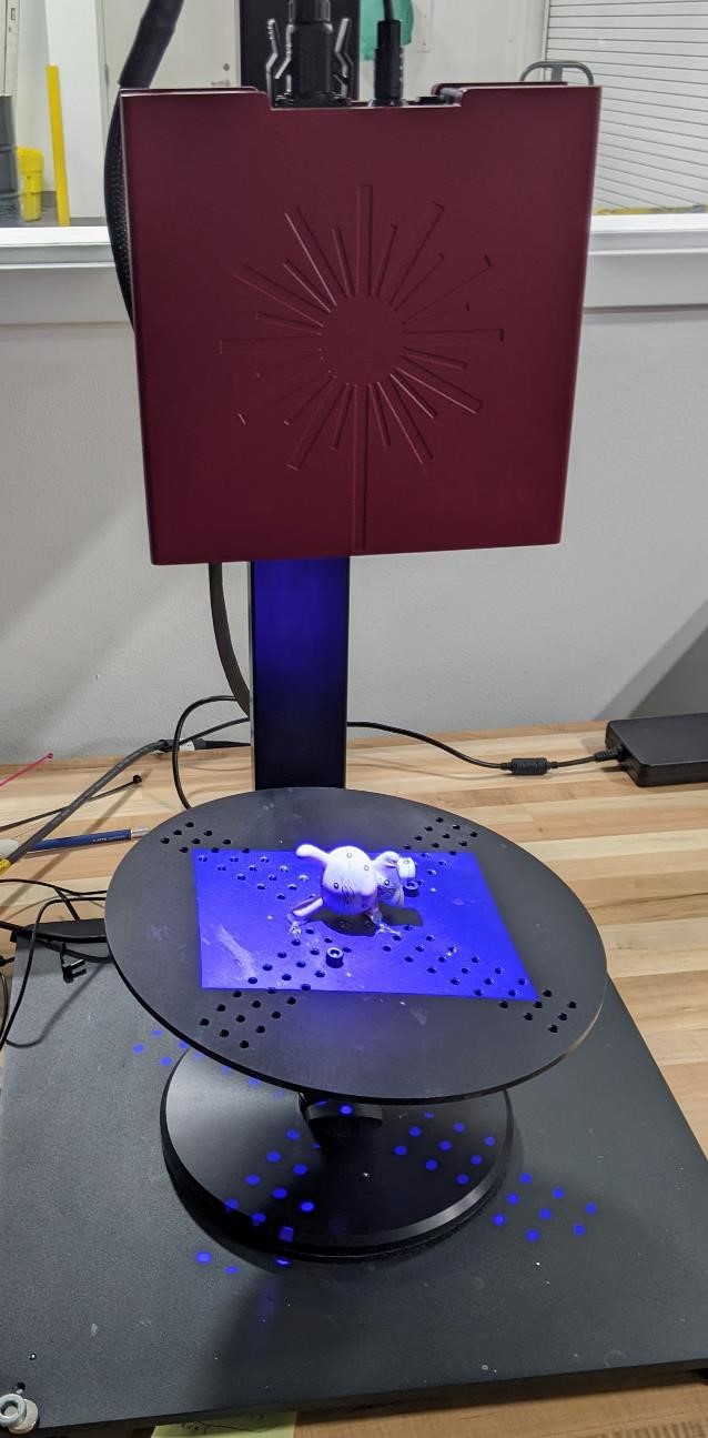
CPCC has had a GOM scanner for years now, but I’ve almost never had the oppurtunity (nor time) to use it. So this was a perfect excuse to sit down and use it. Especially because GOM has a North American office here in Charlotte, at the Portal building on UNCC’s campus.
This is a small structured light scanner that uses sterovision and a small (manual) turn table, and GOM’s proprietary software to scan. The scan area is rather small, approximately 10 inches by 6 inches. The ATOS system from GOM is designed for industrial metrology, and the accuracy of the GOM is very good.
The software is nice, but I have my complaints (ease of use the biggest, lack of some basic features, among others.) That said, the software version I am using is from 2017. I imagine it has changed since.
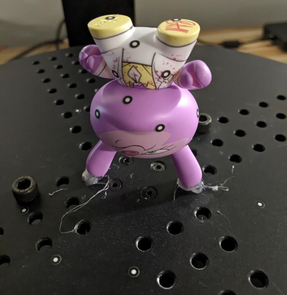
I had a toy that I wanted to scan, it was just something laying around that I thought would be neat to try and scan. Simple, but an organic shape that is hard to classify with typical reverse engineering techniques.
Preparing for the GOM Scanner
While this is a structure light scanner, there are a few things that you may need to do to prepare for the scanning.
The first is that this scanner despises metallic or shiny objects. If the object has a high reflectivity, the scans will likely come out poorly.
What you can do to help this situtation is to coat the the object with a powder or paint.
Most of these solutions are just temporary. A classic spray used in the past was a cure for athlete’s foot, as it came in a spray can, eas easy to apply, created a matte white finish and was fairly easy to remove.
Now there are professional sprays designed for 3d printing that will actually evaporate after a certain amount of time. And there is now a number of options of easy to use sprays.
But if your object needs a coating, go ahead and carefully spray it.
In the Shadows
A quick aside on how this scanner works.
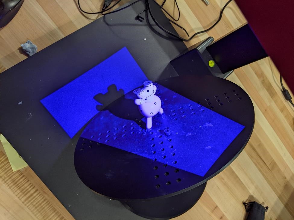
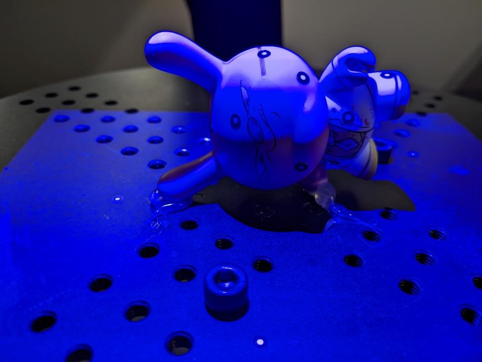
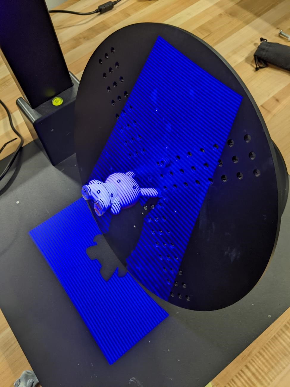
The scanner itself sits above a black turntable. It has two cameras and a light projector. This projector projects blue light at the object, and when you scan, it quickly projects a variety of different stripe patterns on to the model, and takes pictures of these stripe patterns as they “curve” around the model. Because the projector is directly above the center of the turntable where your model is place, there are shadows that the light doesn’t hit, and the cameras can’t see.
The turntable can be rotated, as well as tilted. However, it can only be tilted so far. And even when you’re able to tilt it to close to 80 degrees, there’s almost always an area of your model you can not get a good scan from. This means you may have to actually change the orientation of the model on the turntable and make a new scan.
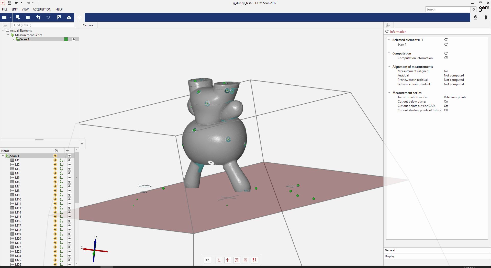
Below is a good example of the shadow. And while the part here obviously can be rotated, there will be parts of the model that will either be in shadow, or difficult for the scanner to pick up.
I need dots, lots of dots.
The GOM uses little “dot” stickers that you can place on your model. These stickers are a black dot in the middle of a white circle. They don’t have to be used if you’re creating a simple model, but they provide the ability to take scans of the item in a variety of positions (ie, many different scans) and then allow these scans to be combined to create a better, full 3d scan.
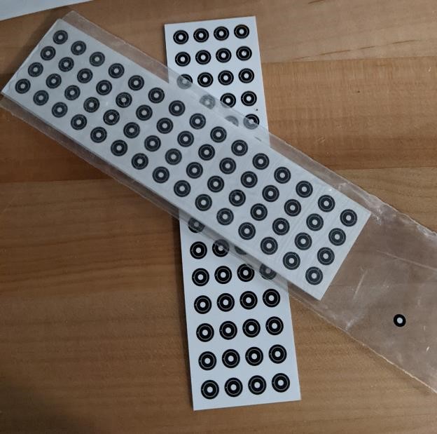
When placing these dots, it’s necessary that at least 4 (preferably more) of the dots that are visible in one scan, can be seen in the next scan (where the model’s orientation on the plate has been drastically changed). This again allows the different scans to be manipulated and combined.
You want to have dots, but you also don’t want to just paste dots over the entire model. Think about the model and which features you want to get the best results from. If you’re only interested in one view, you don’t even need dots. But if you want to get a full 360 degree, complete 3d scan, you should think about where to apply the dots, and how to hold the model in different orientations making as many dots visible in each orientation as possible.
Also note in the below images, there are dots placed on the turntable.
Getting the model to stick to the plate.
The final part of preparing to scan is to stick the model to the turntable so that the table can be tilted, as well as rotated. Blue tack can work, but I’ve found that at extreme tilt angles, this fails, the model moves, and the scan has to be started from scratch.
I’ve had better luck with hot glue. While it’s a bit of a pain, and somethings you don’t want to glue, it mostly works, and isn’t too difficult to clean off of most surfaces.
If you’ve planned out the process of which parts of the model, and how many different positions you may need, this is when you hot glue your model to the turntable.
Set up the computer and scanner
Turn on the laptop computer that’s next to the GOM.
Log on to the computer connected to the GOM.
Login: user password: user
Make sure the GOM ethernet-to-usb connector is plugged into the laptop.
Make sure the gom dongle is plugged into the laptop.
Turn on the GOM scanner. The power button to the scanner is located on a power brick, attached to one of the legs of the table. (The Gom may need to be plugged in as well first.)
Turn out the lights in the CMM room/lab. The darker it is, the better this scanner seems to work.
Open up the scanning software, “GOM Scan 2017”
Finally, can we scan yet?
No. First, select a new project.
Now the software comes up, and you should see a small window with the image of your model (or hand) in it.
You may see the dots on the build plate and the model appear as green dots in the camera window.
Some may appear as red dots with a warning that says “over exposed” or “out of range.” These red dots are overexposed, and we need to fix that. We need to adjust the exposure (this is where turning the lab’s lights off helps)
Find the shiniest, brightest part of the model (it may be the part closest to the scanner)
Center this bright spot with the crosshair in the camera window in the software.
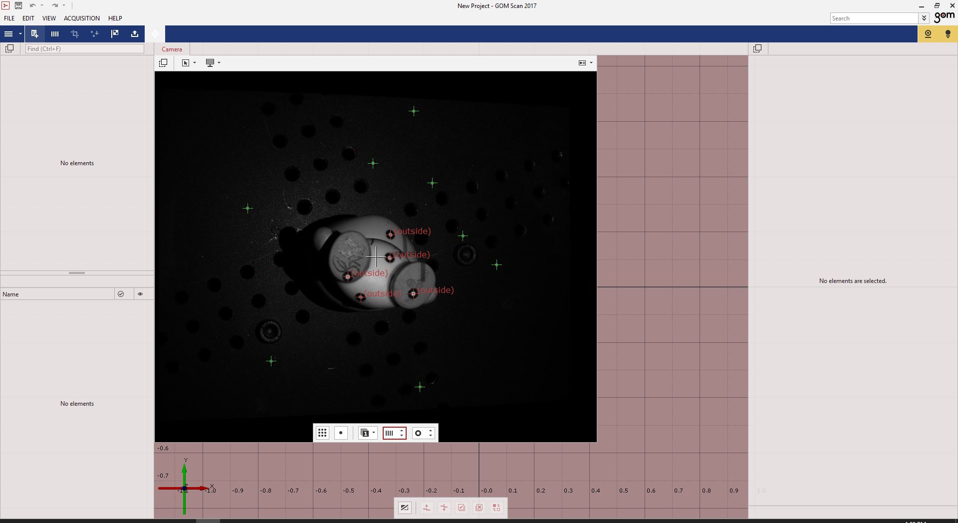
In the small window with the camera view, click the button of a single dot in a square, it’s the “Spot, automatic exposure time once.” There is also a “Matrix” button that may be better depending on what your model is.
In the below image you can see the camera window, and all the green dots, letting me know that the exposure values are good. (yeah, I lost all my screenshots, but I had this picture I took for some reason.)
FFS, I’m losing my patience.
Understandable. Me too, these directions go on and on.
Now, not touching the table or the scanner, press the spacebar on the computer. (this sensor is incredibly sensitive to vibration, if the scanner or part moves, it will give an error and won’t take a picture.)
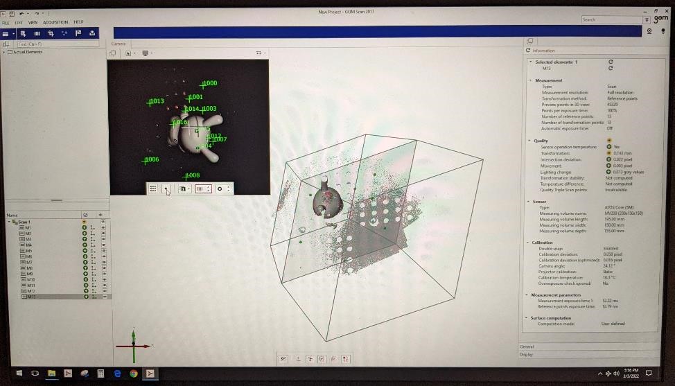
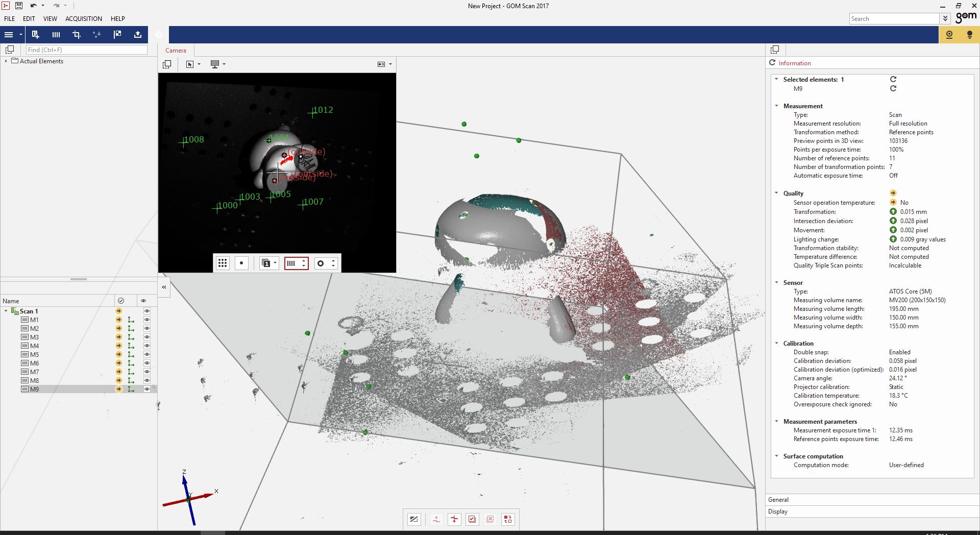
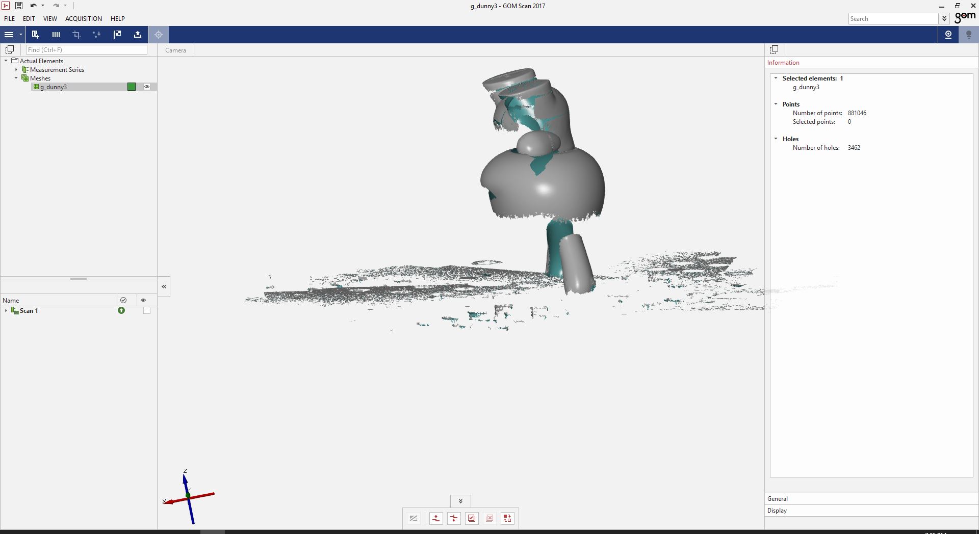
Congrats. You just took your first scanned image. On the large window of the software, you should see parts of a 3d model appear (you may need to zoom out to see it.)
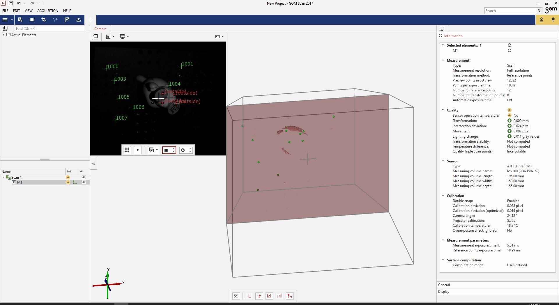
You should be able to see some polygons appear in the main window. You will see the model “build” itself as you take more and more scans.
Now use the turntable and rotate the model and hit the spacebar again.
Repeat as needed.
You can also tilt the turntable. There’s a knob under the turntable. Un-tighten it, and tilt the turntable, then un-loosen the knob and keep rotating and scanning.
As you scan, keep an eye on the 3d model in the software. Make sure it’s not moving, or doing anything strange and adding unusal features (you can always delete individual scans, so it’s no big deal if there is on, but you just want to make sure the model isn’t unintentionally moving on you, and creating a poor scan.)
Are you happy with your scan? Yes? Awesome, now what?
Now we have a scan, but this may or not be useless to you as it is.
Maybe you want to 3d print the part?
In that case, you’re probably going to need to clean the model, as it it usually manages to scan the turntable plate as well as your model.
Exporting as STL
There are a few options. You can export this as an stl immediately and clean this up in another software like Meshlab. Regardless, you’ll probably need to do some cleanup in Meshlab even if you use Gom Scan software for basic cleanup.
I use both. I get rid of the obvious “noise” such as the turntable, and then export the model to work with in Meshlab.
If you wish to export the model, you need to convert all the individual scans into one mesh.
Clcik on “Acquistion”, go find “polygonize..” and click on that. It will take a few minutes, but it will create a mesh of your scans. You can then export this as an .STL.
However, you may want to take scans of more than one position.
Clean Up
You can start cleaning up by going to “Acquisition” -> “Measurement Series” -> “Cut Out Points”
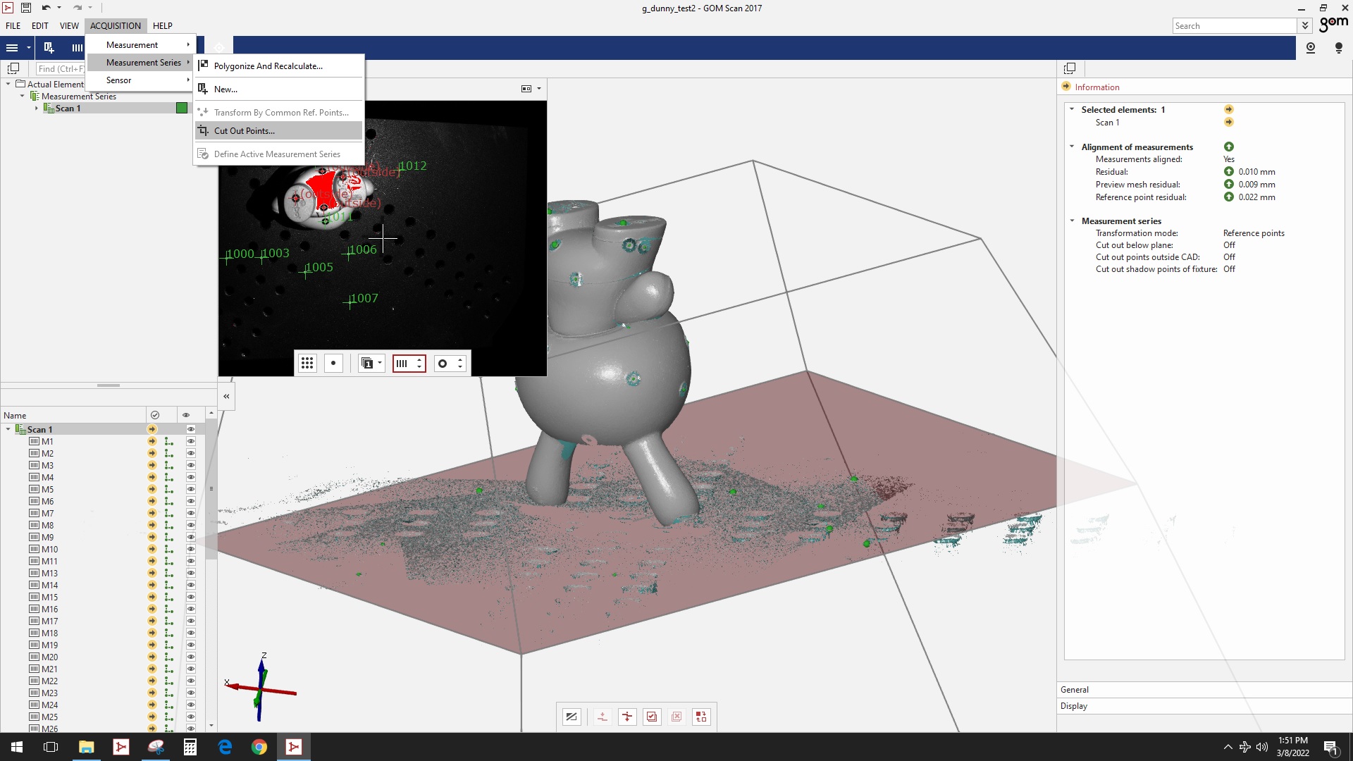
This will let you select certain points to delete.
Click the check box for “Plane”
Then hold down “Ctrl” and left mouse click three points on the area where the turntable appears.
Then a plane appears, with an offset. The offset defaults to 3mm. You can change this as necessary (I usually lower it to 2mm, but it depends on the model.)
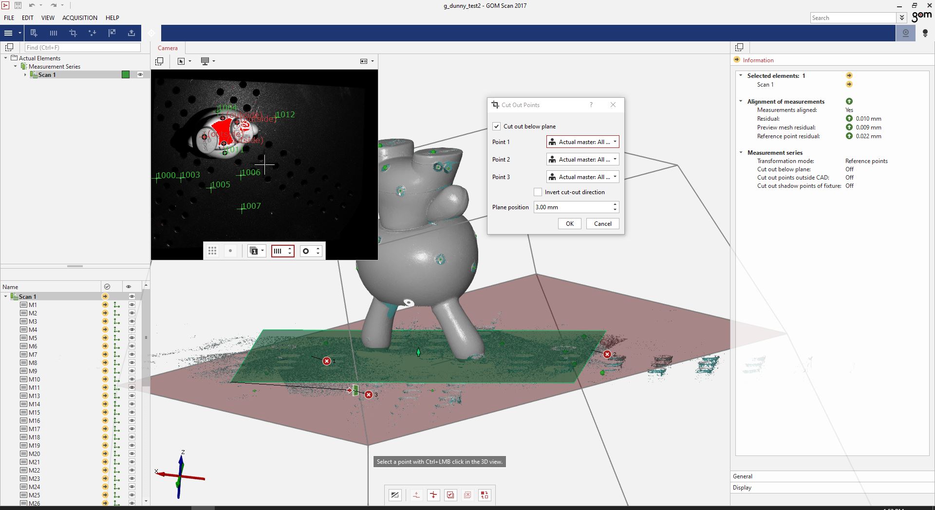
Click okay, and it will delete all the points below that plane.
You can also use “Edit” -> “Selection in 3d” and select an option such as “cut through planes” to drag the cursor around points to select them and then delete them. Be careful here though, you don’t want to delete your model.
Once you have areas selected, you can click “Ctrl-Del” to delete those points.
Adjustments and Notes
Sometimes you may need to change your exposure during scanning. You can again click the “spot” or “matrix” button for automatic exposure. You can also manually change the exposure settings, but I’ve found this is usually more trouble than it’s worth.
Remember not to knock the table.
You can select an individual scan (either on the menu on the left, or clicking on one of the points in the 3d model view, selecting it, and it will turn red, and then deleting it.)
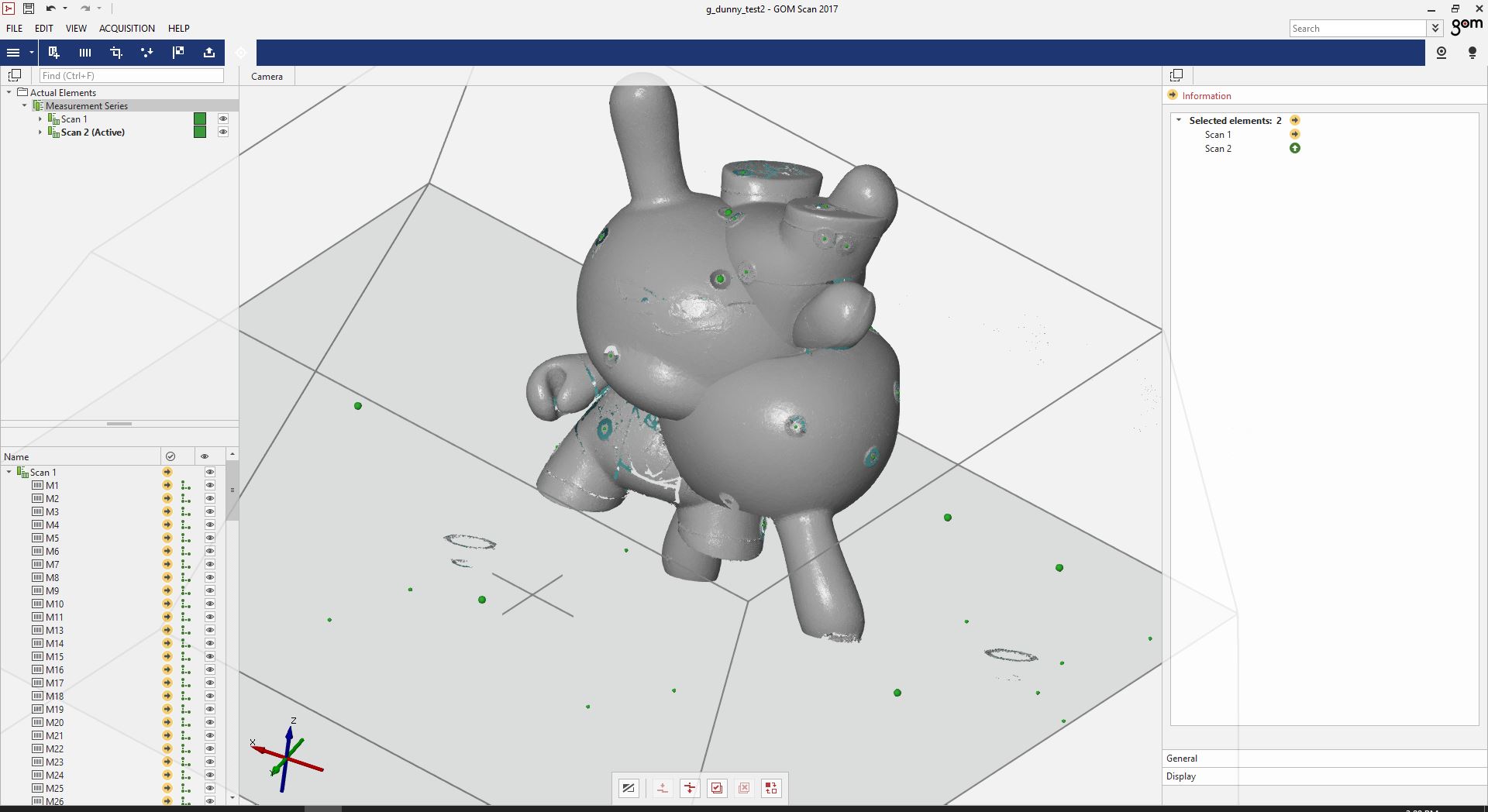
Multiple viewpoints and scans.
If you wish to create more than one scan of the same part, you will want to create a new “Measurement Series.” This will essentially tell the software you’re creating a new scan. But in this case, it will keep the data points all in the same file, so that you can merge the various scans later.
Then you can go back through the scanning process.
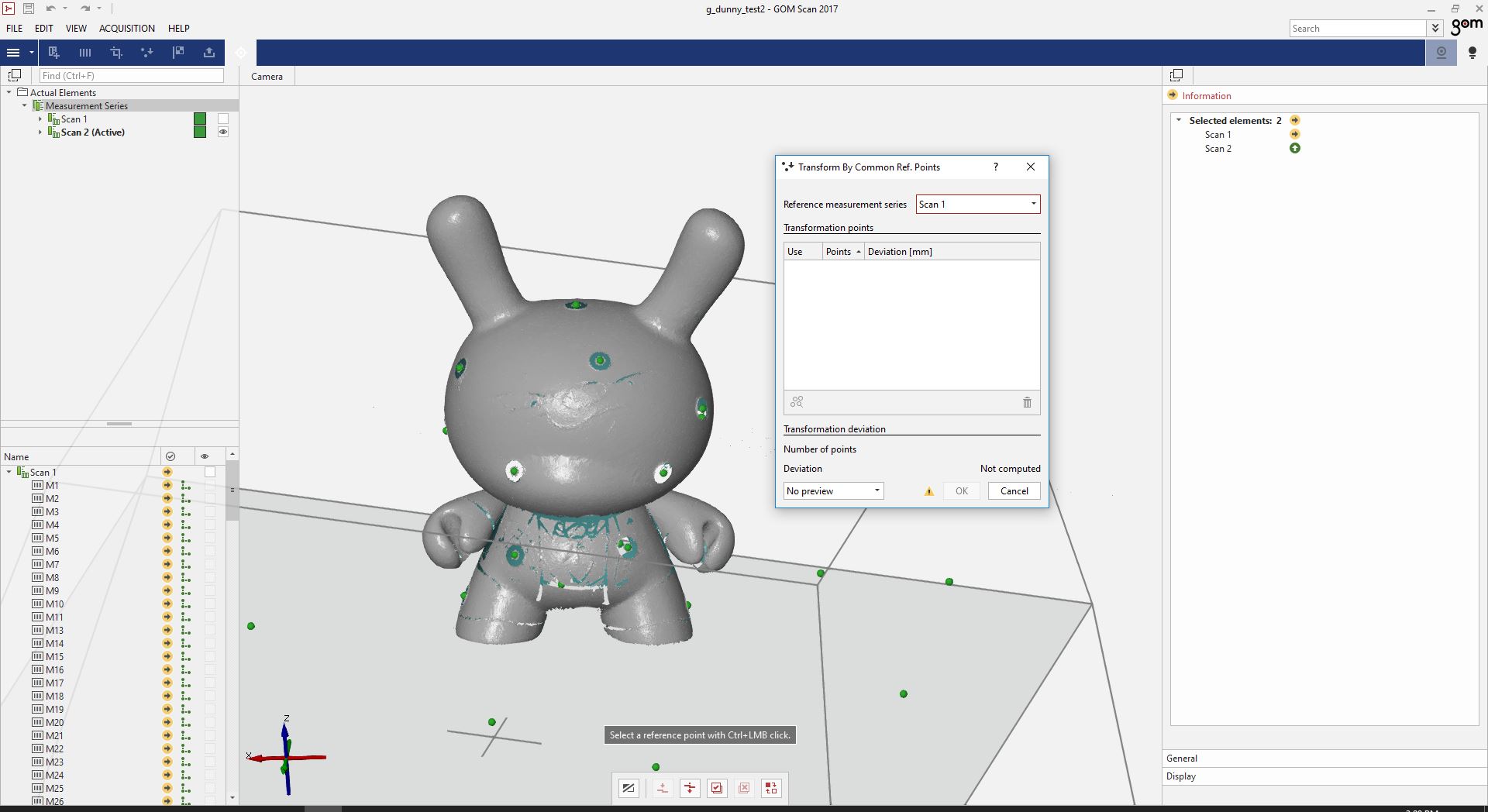
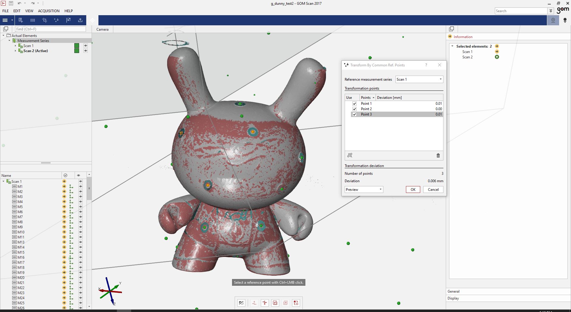
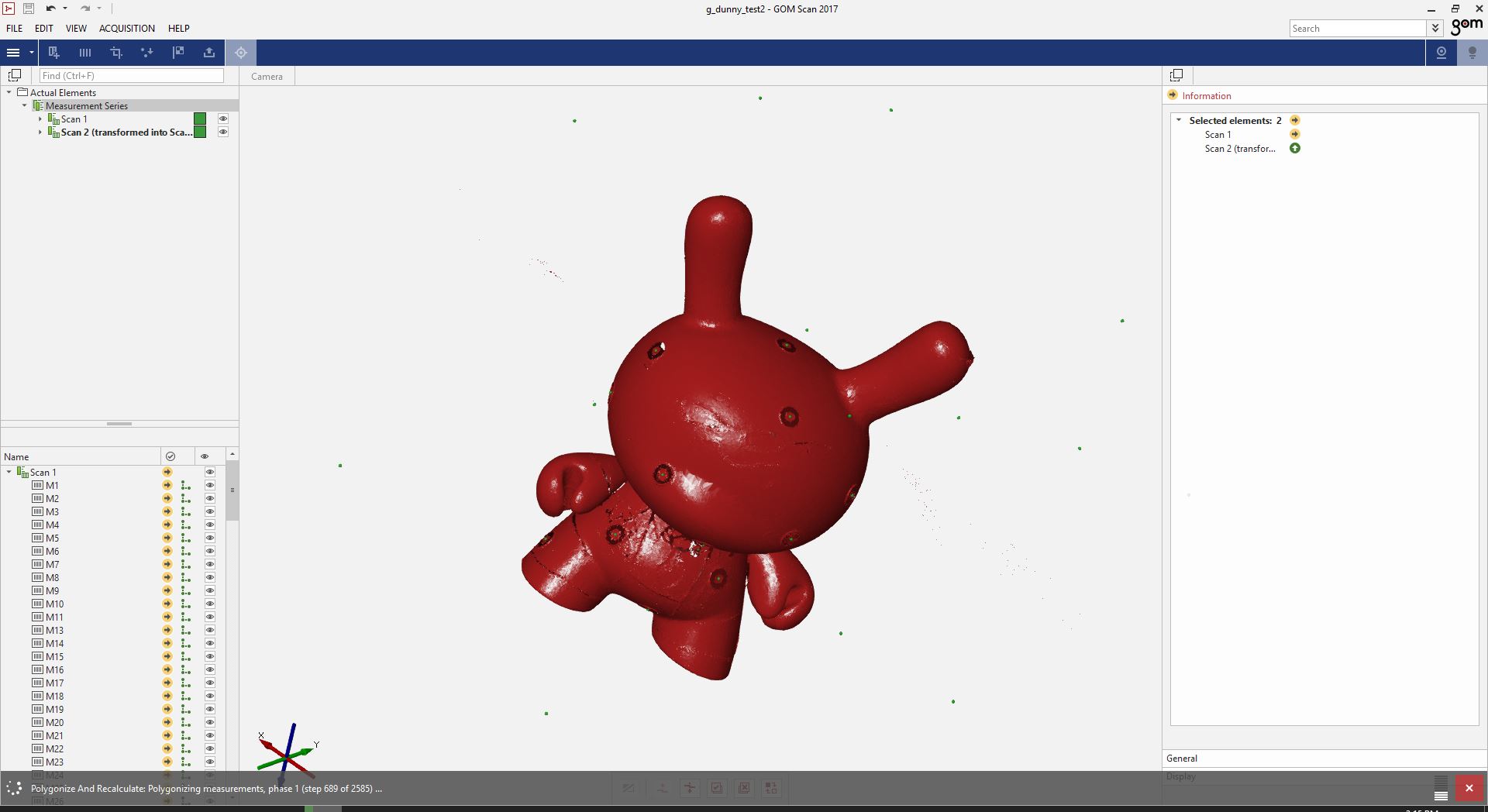
After you have your scans, you “Transform by Common Reference Points.” This was a bit tricky when I used it, and I’m still trying to figure out the best way to do more than 2 scans. But if it works, you should have a very nice 3d scan.
Here you can see two positions of the same model overlaid on one another.
in the “Transform by Common Reference Points” window, you need to choose three points that are on both of sets of scans. This goes backs to having dots, and having the dots be avaiable and seen from multiple sets of measurement series.
Carefully select at least three of the green dots that are found on both sets of scans.
When you have done this, you should see the two models overlap and merge, such as this. model here. One set of scans is in grey, and one set is in red.
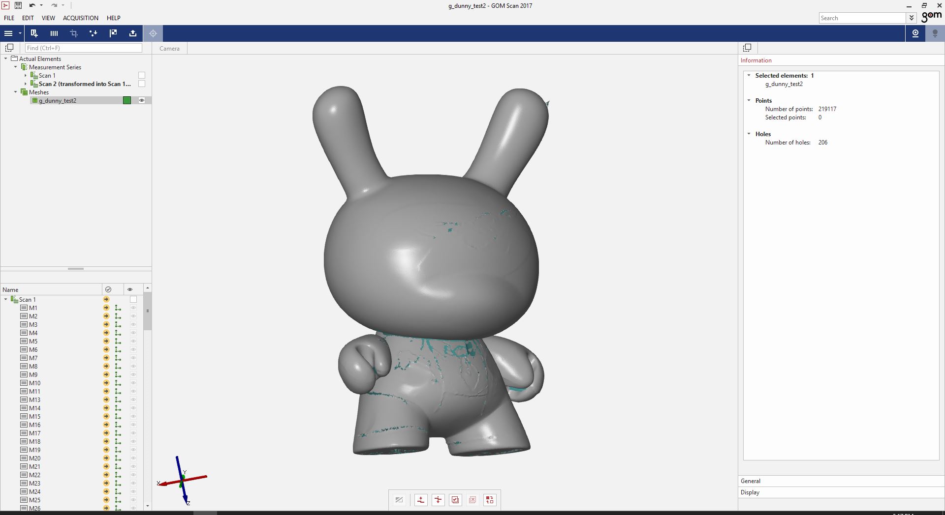
Once you have the model transformed, it still is in a non-standard Gom point cloud. You will want to turn it into a mesh.
To turn the model into a mesh, you can go to “Polygonize” it, and select the standard resolution. This will take the point cloud, and automatically remove the dot stickers from the model, smooth everything and return a high quality mesh, to be saved as an stl.
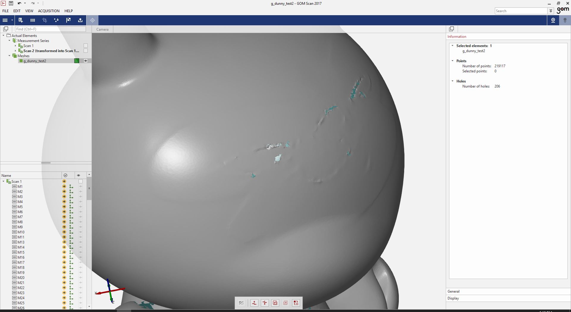
The GOM is so accurate, it picks out the thickness of the paint off of the surface of the model:
More or less getting there.
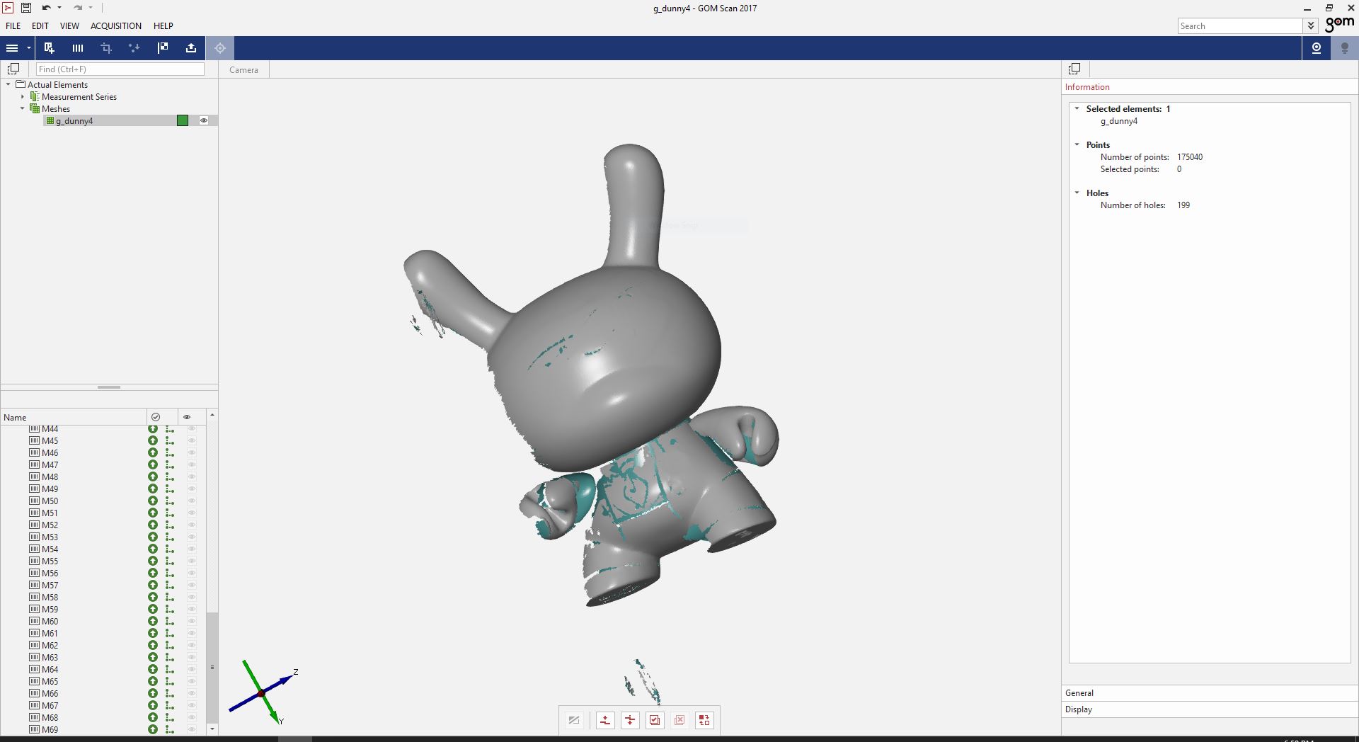
The first time, I somehow lost the .stl files of the scan. I had to go re-scan the model.
This is where you could take it into Meshlab and work with the model to refine it for whatever use you intend to use it for. For more on Meshlab, see Week 3 - CAD
I’ve also created a more detailed look at a method for cleaning up a model and turning it into a solid for more CAD work in Week 10 - Molding and Casting.
Files
For the GOM scanner, the file size of the rough scanned data was over 1gb, based on approximately 200 different individual scans. The final STL was approximately 20mb. Because of this, I do not provide the files for this scan here.
Group Project
This week’s group project was all about testing the design constraints and capabilities of our 3d printers.
You can find the group project for this week at the CPCC FabLab Site for Week 6.
I helped with modeling the test parts and with some of the metrology to determine the printers accuracy and capabilities.
We pushed the printers to their limits.
I learned how quick and easy I could use OpenSCAD to design parts for 3d printer testing.
I also learned not to ever buy red transparent PLA from flashforge. That stuff was junk and caused an untold number of failed prints.
I’ve been using 3d printers for years and years now. I honestly can’t say I learned a bunch, but it was fun making a lot of prints designed to fail, and seeing how well they actually printed. I was surprised very much by this.