14a. Networking - Group Project
April 27 2022
Connect two projects together.
Denny and I were going to make a board using rs485 connection, but unfortunately we had some scheduling issues and we weren’t able to spend much time to work on it.
Denny also had created a rather awesome IR led transmitter that would pass data to an LCD screen. Garrett thought this was quite cool and wanted to make a network using the LED system. Unfortunately, we also didn’t have time to work on this. Maybe a later date… (like so many other projects…)
Low hanging fruit - i2c network
One of the easiet networks to implement for a quick and dirty, though right now a one way network is using i2c. This is a fairly straightforward process using the Arduino “Wire.h” library, which is designed as an i2c communications library.
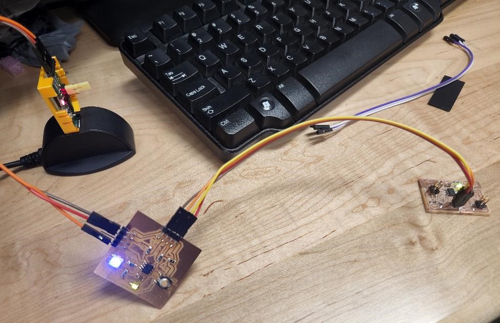
We’ll be giving one device an i2c address, treating it as receiver, and one device will be treated as a transmitter. They’ll communicate over the i2c ports (SDA and SCL) and hopefully one will received the information transmitted by the other. One board will power the other board.
down with the patriarchy!
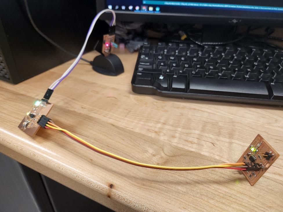
Cori’s board was the master board, and Garrett’s was the slave. This was very emasculating for Garrett. He cried. A lot. Cori just had a smug smile on her face.
Cori’s board told Garrett’s what to do, and it did exactly what it was told too.
Notes about i2c
i2c devices need pullup resistors. I used 10k on my boards, just because… (probably too much, but whatever.)
i2c is not like serial, where you cross the lines (RX connects to TX and vice versa for the other two wires). With i2c, don’t cross the streams. SDA goes to SDA. SCL goes to SCL.
There needs to be one master and one slave (or now-called secondary). The master tells the secondary devices what to do. You’ve got to have a master device somewhere in the communication system or you will not get information.
The i2c have addresses. These are hexadecimal and might appear as something like “0x41” or “0x13”, “0x2E”, etc.
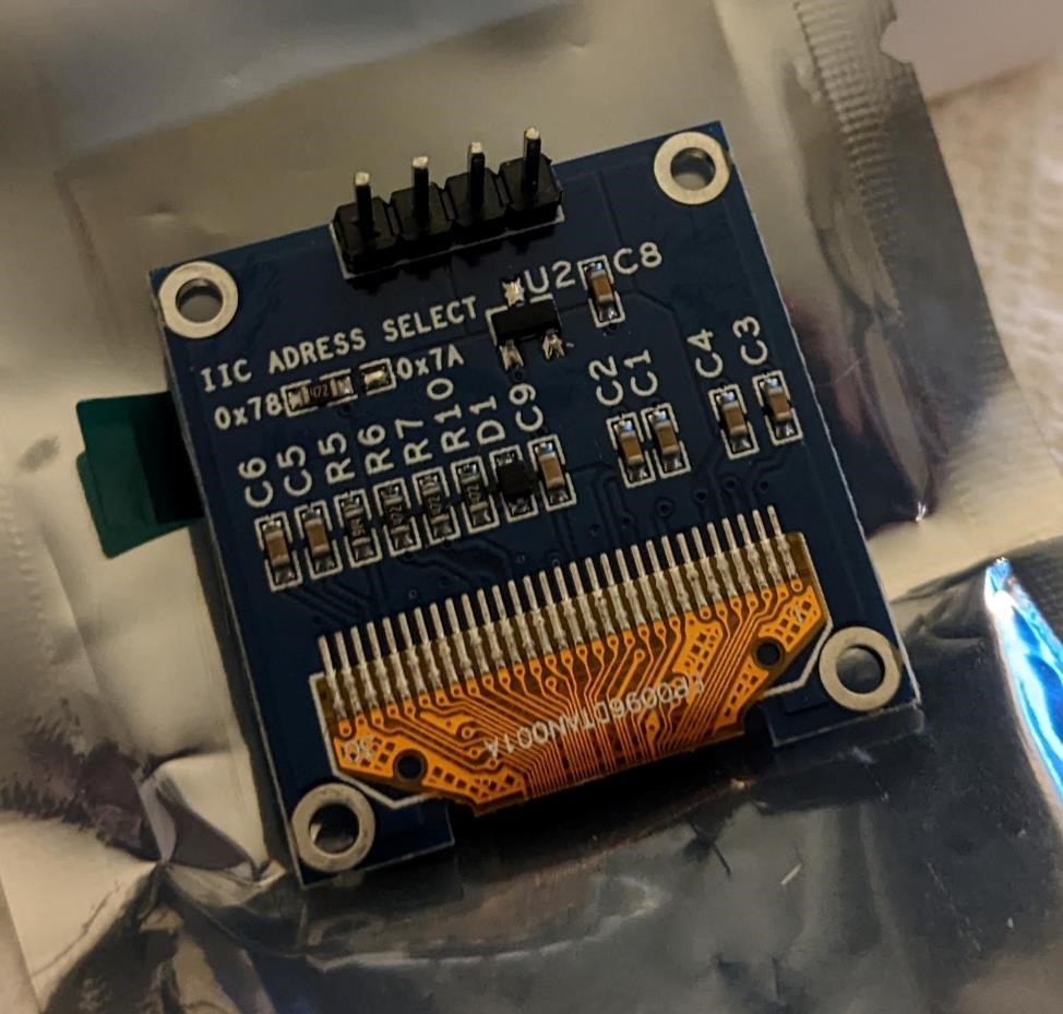
Devices usually come from the factory with a fixed address. Some devices may have an alternative address so that they do not collide with another device, but you’ll usually have to do something to make this work (for instance, connecting a pin on the device to GND or VCC.) Some can be changed with a simple tweak of code (on the device).
Here’s a list of addresses for typical sensors and their i2c addresses from Adafruit: https://learn.adafruit.com/i2c-addresses/the-list. And there are ways to use multiples of the same sensors, though you have to be research this to make sure.
Some devices you can change their i2c address, in the following case by moving a resistor from one pad to another.
(And see Garrett’s Week 12 for more information on finding out your devices i2c address.)
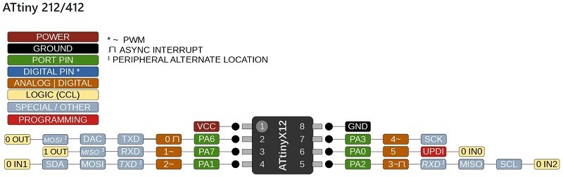
Because we’re using the Attiny412 and megaTinycore, this document is specifically about the attiny412 and i2c (“wire” in arduino): https://github.com/SpenceKonde/megaTinyCore/blob/master/megaavr/libraries/Wire/README.md (this is not the only i2c library, but it’s one that is very often used in Arduino code.)
The 8 pin tiny uses PA2 (SCL), PA1 (SDA).
And the typical attiny412 reference:
The Code
Master LED Blink Test i2c Code
// Down with the Patriarchy!
#include <Wire.h>

byte led_state;                      // a variable, storing the led "on" or "off"

void setup() {
  Wire.begin();                       // initialize i2c system
}

void loop() {
  led_state = 1;                  // value of "1" will be set.
  sendDataWire();                 // call the function to send the data ("1") over I2C
  delay(500);                     // wait half a second
  led_state = 0;                  // change value of data to "0"
  sendDataWire();                 // fall the function to send data.
  delay(500);
}

void sendDataWire() {              // This is where it actually uses the i2c system to send data
  Wire.beginTransmission(0x54);    // prepare transmission to slave with address 0x54
  Wire.write(led_state);           // Write the received data to the bus buffer
  //Wire.write("\r\n");               // add new line and carriage return for the Serial monitor
  Wire.endTransmission();           // finish transmission
}
Secondary LED Blink i2c Code
// No Masters No Slaves
#include <Wire.h>                 // This does a lot. Handles hard work of i2c connection.

int led = 4;                      // the pin that the LED is connected too.

#define MySerial Serial           // This is using the "serial" library (built in)
                                  // and gives it a name, "MySerial." We'll call "MySerial"

void setup() {
  pinMode(led, OUTPUT);             // turns the led pin to output, to turn led on/off
  Wire.begin(0x54);                 // join i2c bus with address 0x54
  Wire.onReceive(receiveDataWire);  // give the Wire library the name of the function
                                    // that will be called on a master write event
  MySerial.begin(57600);
}

void loop() {
  delay(100);                   // Doesn't do anything, main action starts in setup
}


void receiveDataWire(int16_t numBytes) {      // receive data over i2c in 16bit int
    byte led_state = Wire.read();             // get data from i2c, variable "led_state"
    if ( led_state == 1) {                    // if it's 1, do the below:
       digitalWrite(led, HIGH);               // Turn the pin for the led on High (led on)
       MySerial.write("LED On");              // send data out over serial saying "Led on"
       MySerial.write("\r\n");                // Writes a newline to serial monitor
    }
    else {                                    //but if it's not a 1...
       digitalWrite(led, LOW);                // send a low to the led pin, turn led off.
       MySerial.write("LED Off");             // and send this text to serial monitor
       MySerial.write("\r\n");
    }
}
Future goals
Have a larger network between Denny, Cori, and Garrett’s boards that will be able to share sensor data, especially using wifi would be awesome.
References and Resources
This was basic info on how to create your own “i2c” system. https://www.electronics-lab.com/build-i2c-sensor/ which uses an Attiny85 with a light sensor acting as an i2c device.
And we came across this from another FabAcademy link: https://www.instructables.com/Arduino-I2C-and-Multiple-Slaves/
Thankfully, the Arduino IDE has a lot of support just for this. It uses the Wire.h library.
This library takes care of much of the heavy lifting, and very much like the Serial library, makes it fairly easy to communicate over i2c. For this, I’m using the tinyMegacore Wire library (which is supposed to be a direct close for Attiny processors.)