16. Wildcard Week
May 11 2022
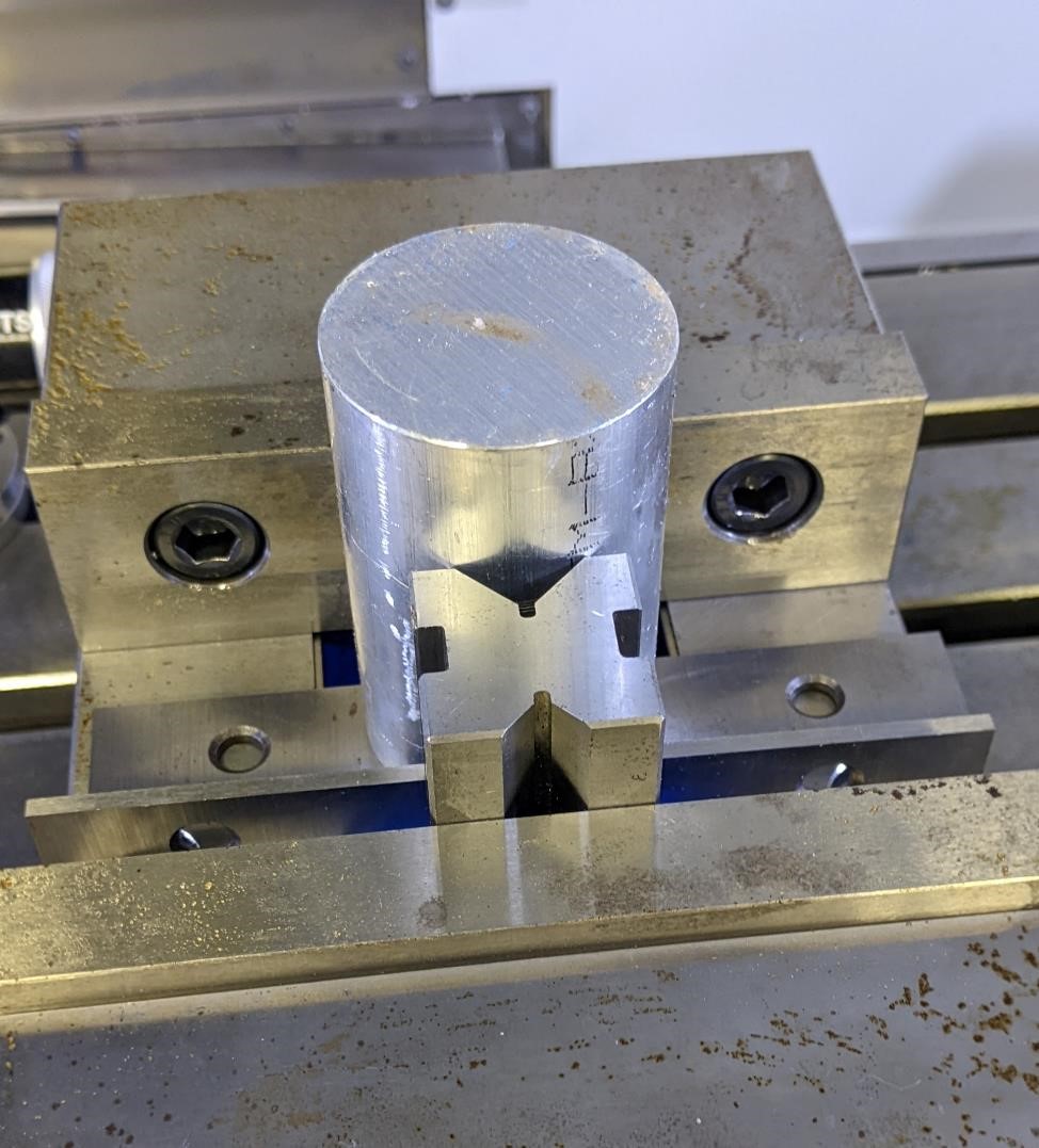
For this week, I chose to do a 5 axis project on a CNC milling machine.
I first designed a part that I would have a hard time making on a traditional 3 axis machine and then started the CAM programming (creating toolpaths to mill out the part.)
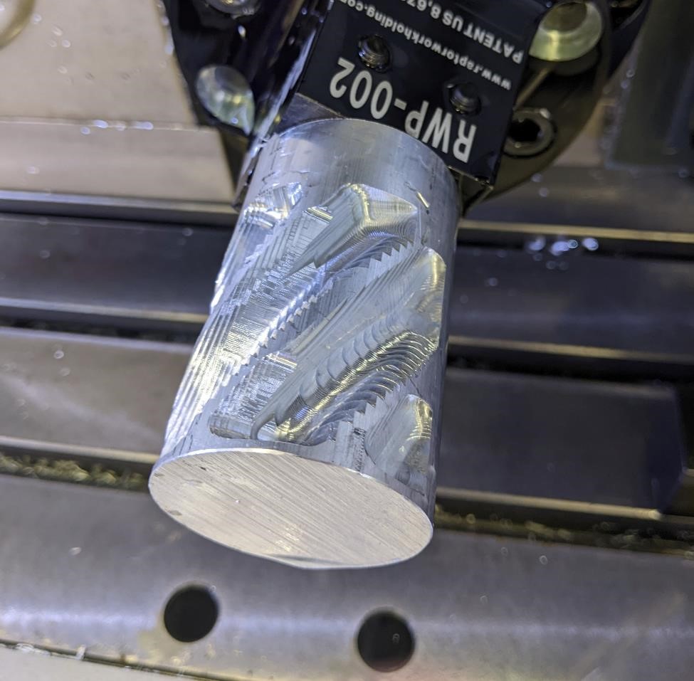
(The above is just after the roughing of the part, but I loved watching the light reflect off of it as it spun around. Also RATM)
Some of the more basic tasks (3d modeling, CAM, running a CNC mill), I’m going to skip over. To see more about this, please look at this page on using a 3 axis CNC mill.
Modeling the part
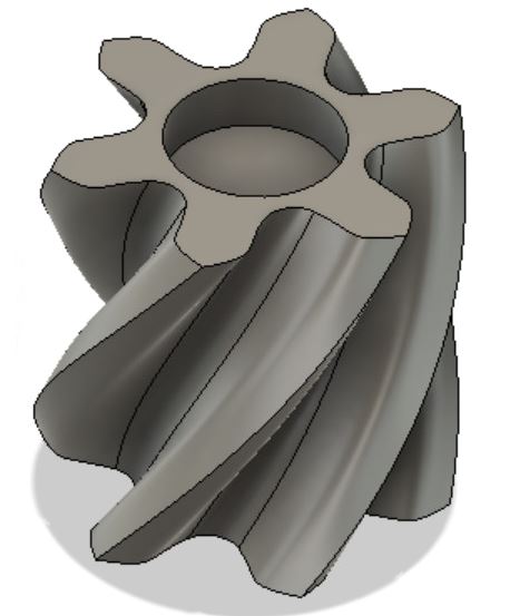
To model this part, I simply created a 6 lobed “gear” shape.
I drew a 2” diameter circle (as this would be my stock size I’d be using.) then I created a curve, mirrored that curve around a center line, and then used a “circular pattern” to place this around the circle 6 times.
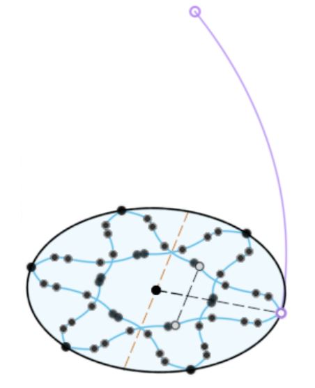
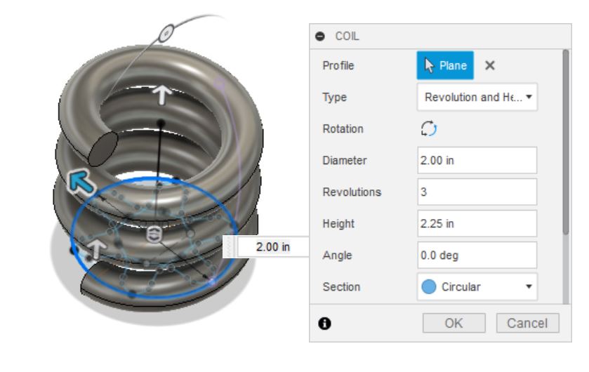
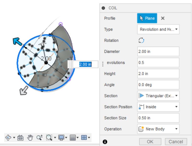
I then created a model coil, on the bottom plane, with a 2” diameter.
Then for the settings on this coil, make the height whatever you’d like, such as 2”, and then I change the revolutions to 0.5 or less, I use the “inside” section position, and make it a “Triangular (external)” section. This will give us a nice sweep, not too extreme to be easily machined.
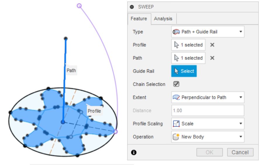
Then create a new sketch, and then create a line off the the 3d coil (using “select 3d geometry” to sketch), and use this and a I create a vertical line from the center point of the design to whatever the height of the model.
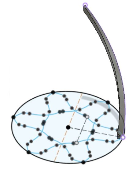
I then use these to “sweep” the sketch. This created the main body and 3d shape.
For the sweep, I selected “path + guide rail.” and I selected the straight vertical line as the ‘path’, and the coil line as the ‘guide rail’, with the main design as the ‘profile’ of course. (though playing around, I don’t know how much the path and guide rail matter in terms of which is which, unless you play with the “extents”)
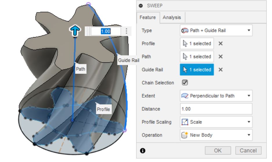
I did add fillets to the internal portions of this that came to a sharp crease, as this will not be easily machineable with the tools available to me.
And that’s it. A very quick, simple way of creating a twisted model.
Five Axis Machining
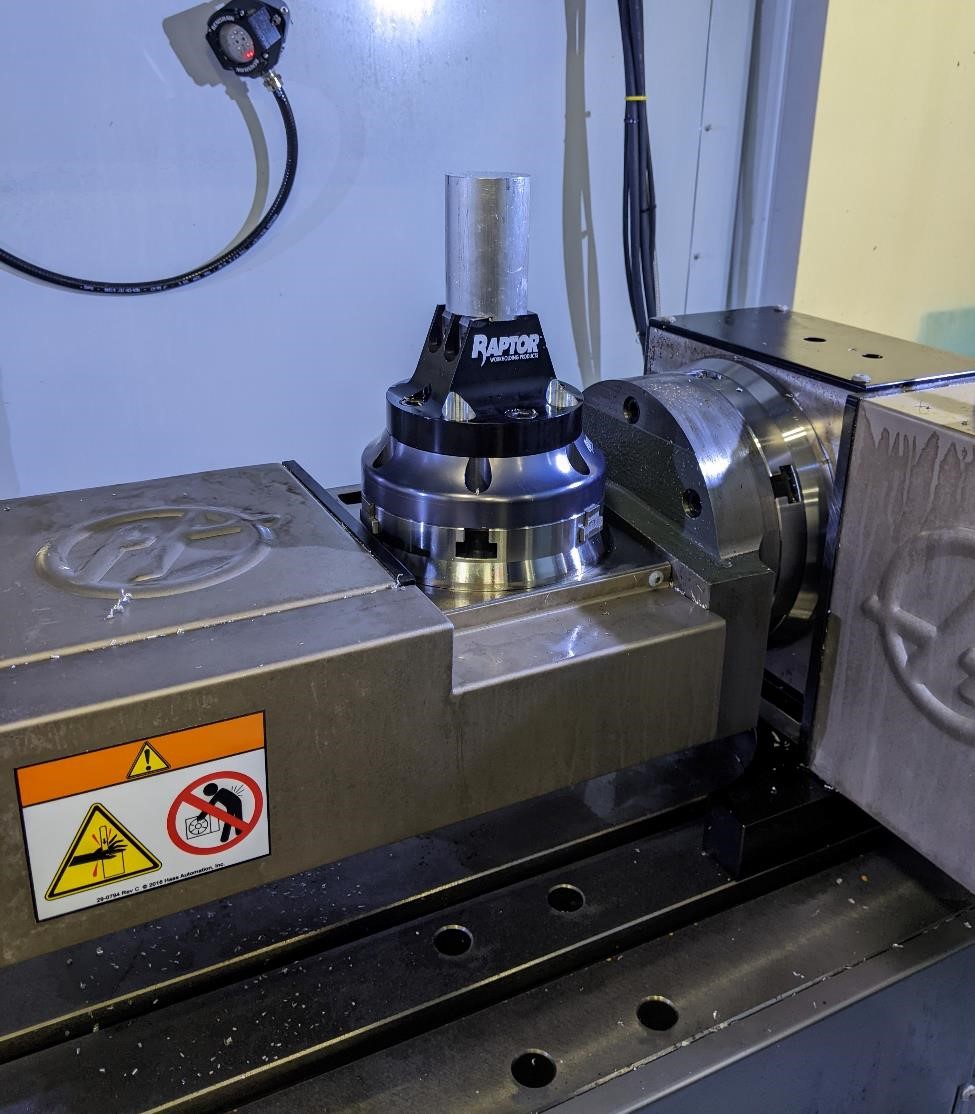
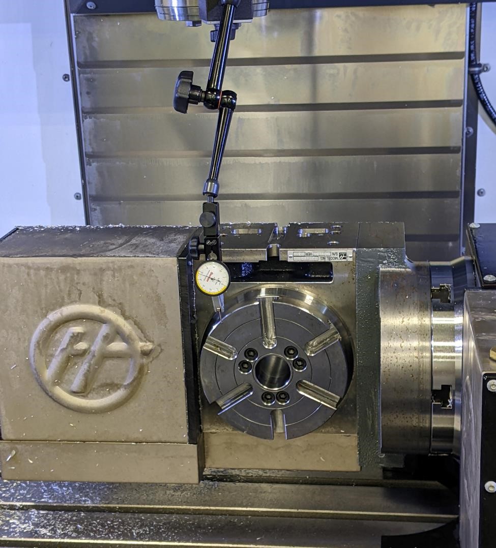
On the Haas VF4 mill with a 5 axis trunnion (this is an add-on, the machine wasn’t purpose built for 5 axis. That’s going to make this such a much more fun project.)
The A axis rotates around the X axis (in this machine running left to right). The C axis rotates around the Z axis (vertical). (One way that I remember which is which is that with our traditional X, Y, Z axises, they are often said in alphabetical order. The same with A, B, and C. And these axises directly relate. So A and X are related, B and Y, C and Z. But note, this is not always the case for every machine.)
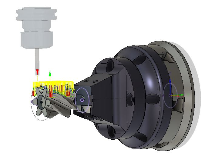
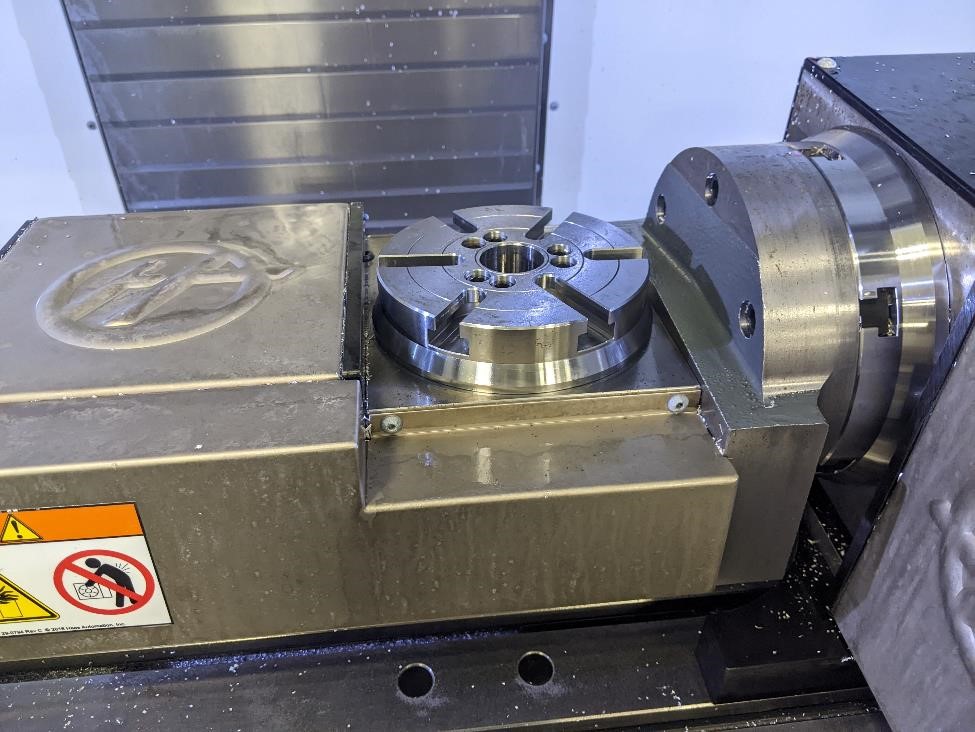
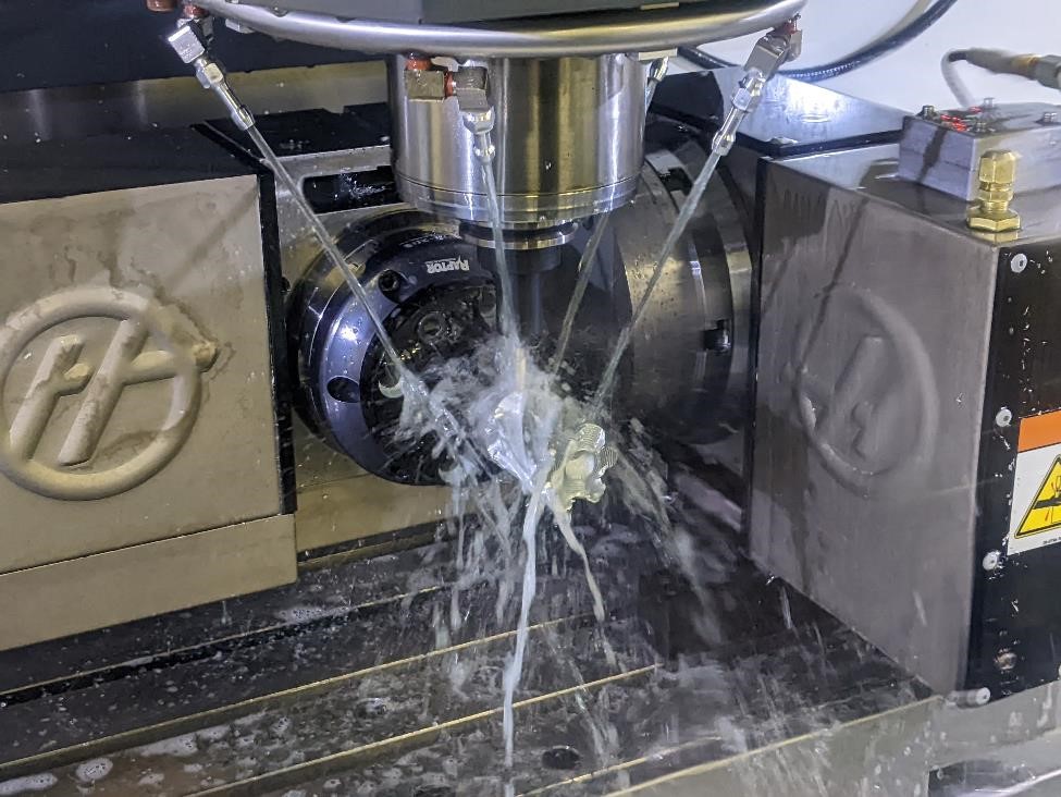
Here’s an image of the 5 axis trunnion in the machine with a piece of aluminum stock ready to be machined.
Fusion 360 and CAMing
I used Fusion360 for this project. And while Fusion360 is excellent at some things, at others it is less than excellent. Five axis is one of those things that Fusion360 does not excel at.
For one thing, you’ll need the advanced multi-axis extension (which I have access to as a machining instructor.) If you don’t have this, you’ll be hard pressed to do much multi-axis machining.
Fusion360 can handle 3+2 machining without too much issue. (this is the case of doing traditional 3 axis milling, but simply rotating the part to a fixed position, and moving it around each time in order to have a new setup. You may have 3 axes moving at one time, but you won’t have 4 or 5 axes running simultaneously.
And of course, when you do have 4 or 5 axis moving, this is called simultaneous 5 axis machining.
Fusion struggles with any type of simultaneous. There are only a few toolpaths that are even capable of handling simultaneous 5 axis in Fusion. These are the “Swarf” module, the “Multi-axis Contour,” “Rotary,” “Flow” and “Steep and Shallow.” And honestly, they all suck.
Programming
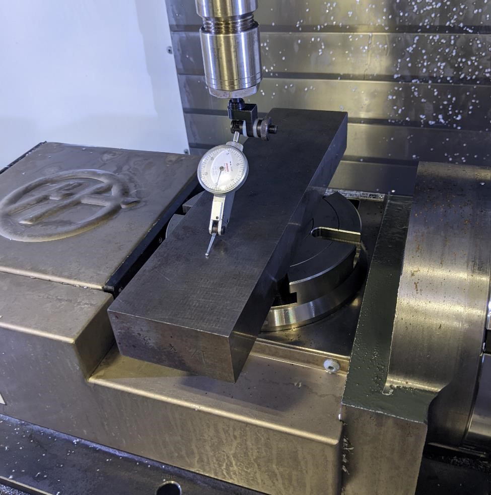
First, we need to program our part origin, where all the coordinates for the machining are based off when we actually put the stock into the mill to machine. You need to know the Center of Rotation, as this is what everything will be based off of. If you don’t know what your Center of Rotation is, see below on how to properly find it.
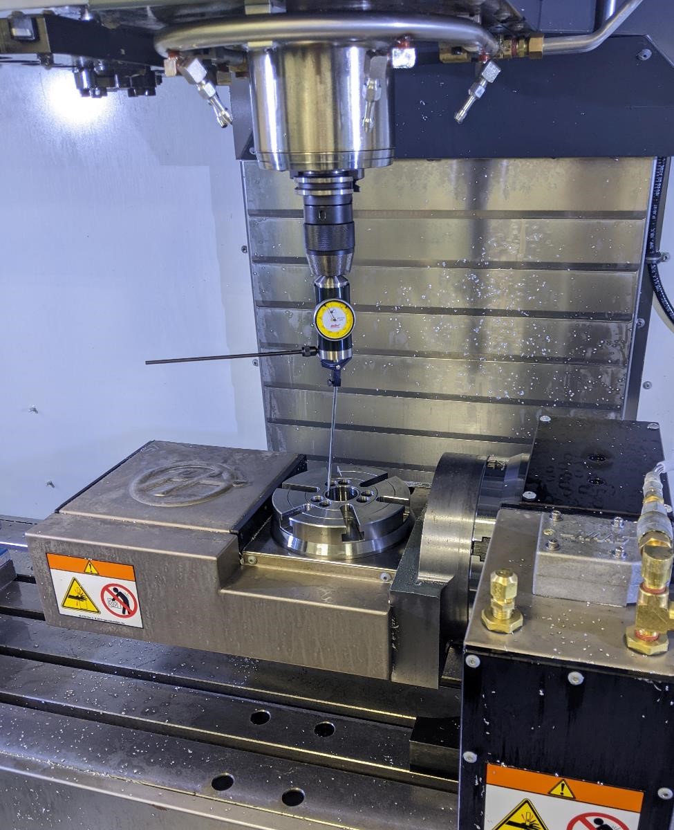
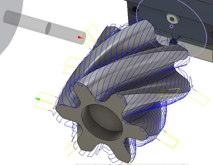
The below image shows the center rotation of the Haas VF4 5 axis trunnion. It’s where the gnomon is located (the red, green, blue X, Y, Z arrows in the bottom.) This is the origin point of our programmed part.
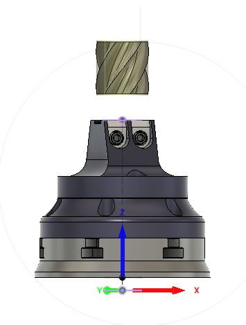
I’ve also added the fixtures and the C axis platter that we’ll be using to hold the stock. This helps because I can tell Fusion360 to avoid these areas to help with keeping the machine from crashing (at least hopefully.)
I’ve also added the stock size, and if you’ll note, I’ve added extra length to the stock so that the part is about 1 inch above the fixture. I did this to give me more clearance, because I very much don’t want to crash this machine.
Tooling
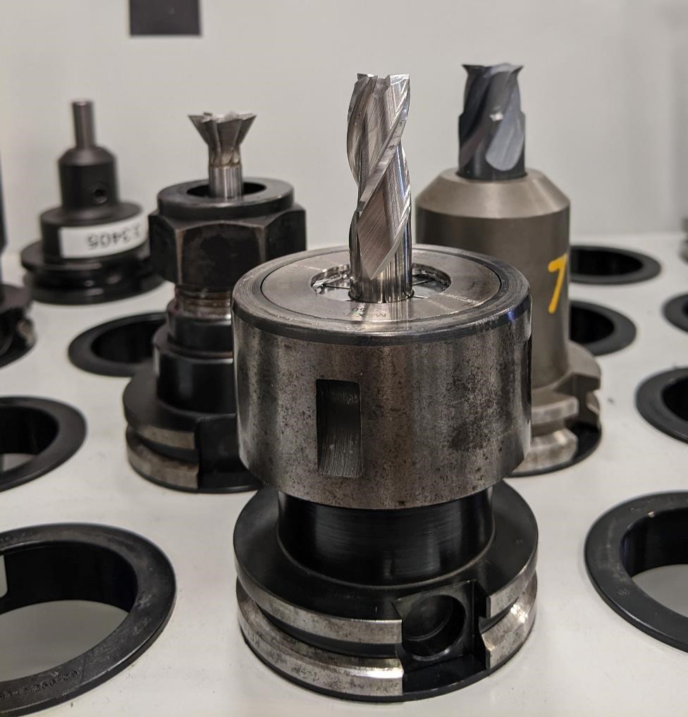
This part just uses two tools:
A 1/4” 3 Flute, HSS end mill and a 1/4” 3 flute ball nose end mill.
In 5 axis machining, you need to pay special attention to the clearance of your tools and toolholders. While this is true in every form of machining, in 5 axis, there tends to be less clearances between the trunnion and the toolholders, and so things are tighter. In simultaneous 5 axis machining, it’s also more difficult to read the g-code and understand what the tool is doing, making it more difficult to catch any interference issues while the part is actually being machined.
To help with this, in a perfect world, you would exactly model your tools and toolholders, and the CAM program would do it’s best to keep these from crashing into the fixtures/trunnion. It’s not perfect, but it’s one more system in place to help with avoiding crashing the machine.
I’m lazy, I programmed this for large clearances, I’m confident, I’m not going to take the time. But I should.
Toolpaths
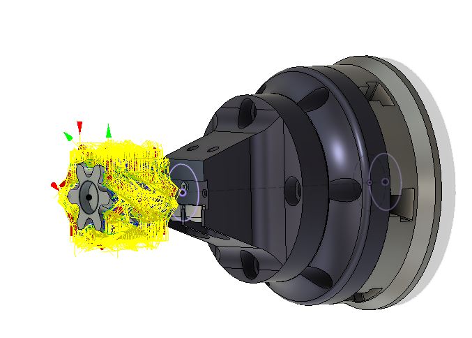
Here’s a list of toolpath’s we’ll be using. Note that for this particular model, I can create one toolpath and “pattern” it around the part 6 times. This saves time and just repeats the same toolpath. I do this with the roughing and the finishing. (there is machining inefficiency with this, as you’ll be cutting air occassionally, but I’m trading programming time for machining time. Also, in this case I have a number of undercuts, and this is an easy way of machining these areas. Also when I want a nice surface finish, having the part cut multiple times from different angles helps provide this high quality surface finish (sometimes at least.))
We will face the top of the part by just using a 1/4” flat end mill, and then add the bore in the top for a 608 ball bearing. (bearing is 0.867” diameter or so.)
We’re going to rough out the stock, and remove most of the material. This has a very large stepover and step down (about 0.0375 if I’m not mistaken.) This is designed to remove material quickly.
This will leave a very faceted surface, as we’re using a flat end mill. It can’t do curves very well. Because of this, we also leave stock on the walls that we’ll go back and clean up. I’m leaving about 0.020” stock on the walls for cleanup.
For the finish pass, we go back with the ball nose endmill to clean up and create a much smoother, higher quality surface. The stepovers for this are very fine, about 0.005” per pass. This could be tighter (it could be larger as well), but because of the machining from various angles, I feel like I can get a good surface finish with this particular stepover.
For more on surface finisn and stepovers, check out this video here: https://www.youtube.com/watch?v=XSiPWq4Osmw&feature=youtu.be
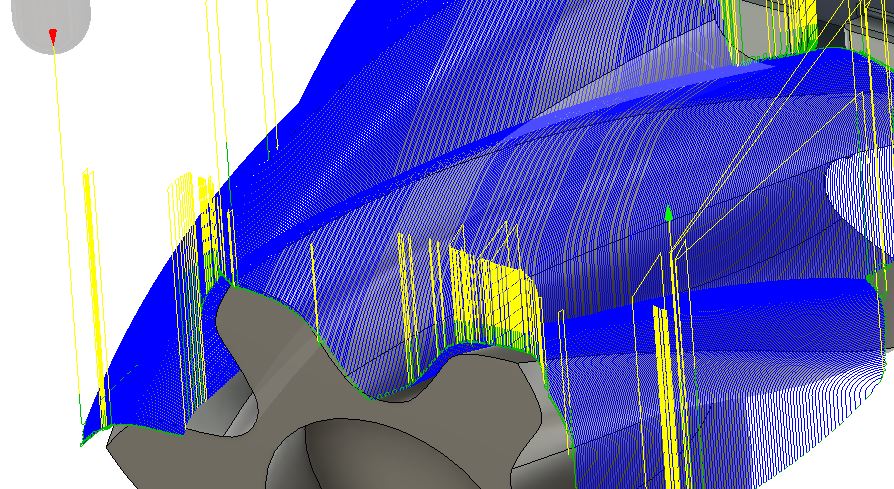
But because this part is cylindrical, and I can’t machine it from the traditional 3 axis position ( not easily at least), I’m rotating the part around the X axis, that it points to around the Y axis and I can machine it.
Here you can see how I have “tilted” the part in order to machine the side of it, rather than just the top of the part as you would see in a typical 3 axis mill.
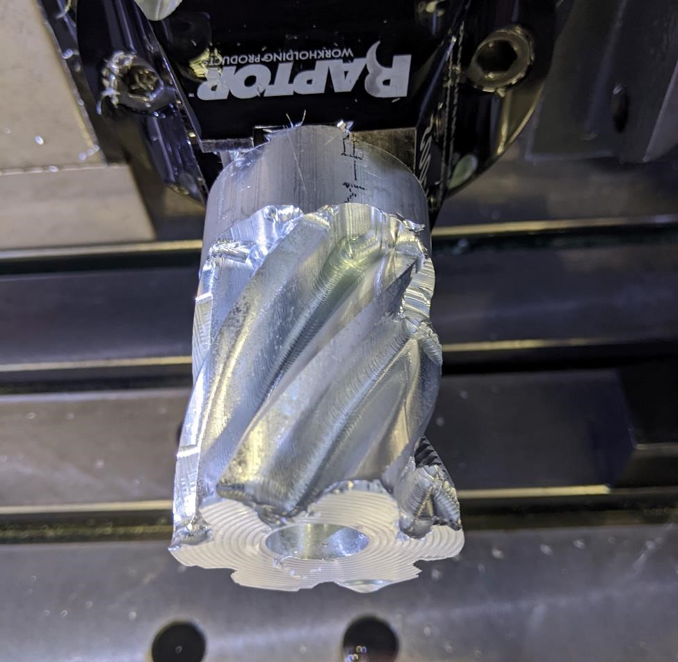
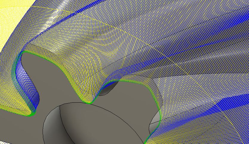
The first image here shows the toolpaths, and the second image shows the same toolpath being “wrapped” around the part 6 times.
This is the roughing strategy toolpath, designed to get rid of as much material as fast as possible.
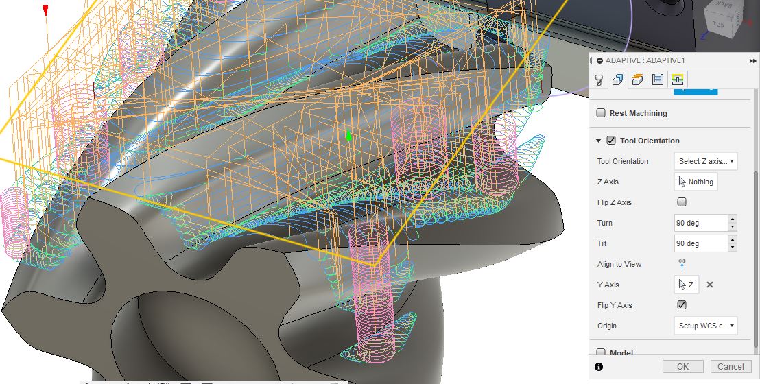
The finishing toolpath. This takes much longer to run, as it has a much finer stepover (the distance between the tool going back and forth over and over again.) After this part was completed, I noticed that the stepovers are dynamic on this toolpath, and it explains some of the rougher finishing I got on the internals of the part. I’ll have to correct this if I make this part again.
Speeds and feeds were very conservative. I would have liked to run them faster, but there were limitations in the tool pathing that required to be conservative where the chipload would dramatically increase. (It wanted to bury the tool into the back of the part too often essentially. Given more time, and if I wanted to spend more time on this project, I could have edited this out.) I left the feeds at the slow side to handle these transitions, otherwise I would have been running this almost wide open.
The speeds and feeds were 7000 rpm and 50ipm for both the 1/4” square end mill and the 1/4” ball nose end mill.
Preparing the stock.
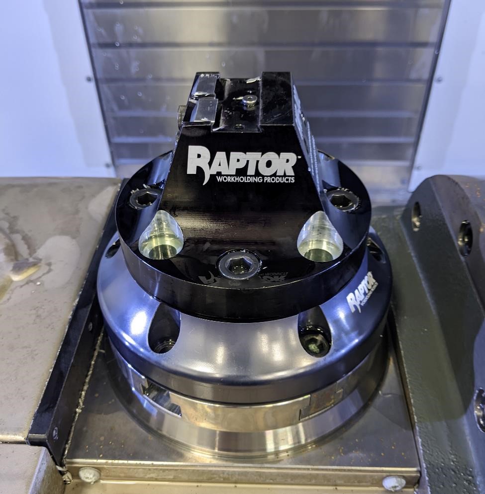
The first thing I need to do in order to machine the part is to prepare the stock. While I often use a Kurt 6 inch vise to hold my stock and machine it, due to the nature of the 5 axis, a large vise like this is not ideal. There are many smaller vises designed for 5 axis to use, but there are a number of designs specifically for 5 axis machining.
We use one of these, which is a dovetail holder (made by Raptor, I never really got this pun until just now.) This will hold onto a piece of stock with a 30 degree dovetail that is approximately 0.125” high, by 2” in length.
When I first saw this way of holding stock, I did not believe it would hold stock well enough to not put the stock out of the holder. However, these dovetail holders are incredibly strong, and are able to hold the part without it being yanked out of the fixture by the tool and machine.
I used 2” diameter aluminum round stock, just over 3” long.
Making the Dovetail
Holding the stock in a normal 6” vise, I used a vblock to hold onto it.
I then used a 0.50” 3 flute HSS flat end mill to face the part, and to create a boss on the part where the dovetail is.
I then take a 1/4” flat HSS end mill and create a small pocket in the dovetail area, as there is a locating pin (that’s 0.265” diameter, because why make this easy?) This pin helps to center the part, and to help with repeatability.
In the above image, the forground is the 1/2” 3 flute endmill. On the back left is the dovetail cutter, and on the right is a specialized tool for making milling and making dovetails in one operation.
Finally, I use a dovetail cutter to just take a shallow pass near the boss, and it creates small dovetail cuts on each side of the boss to create a dovetail.
(How do we know Garrett made this?)
And then the stock is ready to flip, place in the dovetail fixture and start machining.
Setting up the machine.
But before we start, there’s a number of things we have to do. Because of course there is.
Since this machine has an add-on 5-axis trunnion, and it’s often used by students, we want to check to make sure that it’s been trammed, that is, it is aligned with the X and Y axis, and not twisted. We also need to make sure the platter is flat (perpendiculard to Z axis) and then find the Center of Rotation.
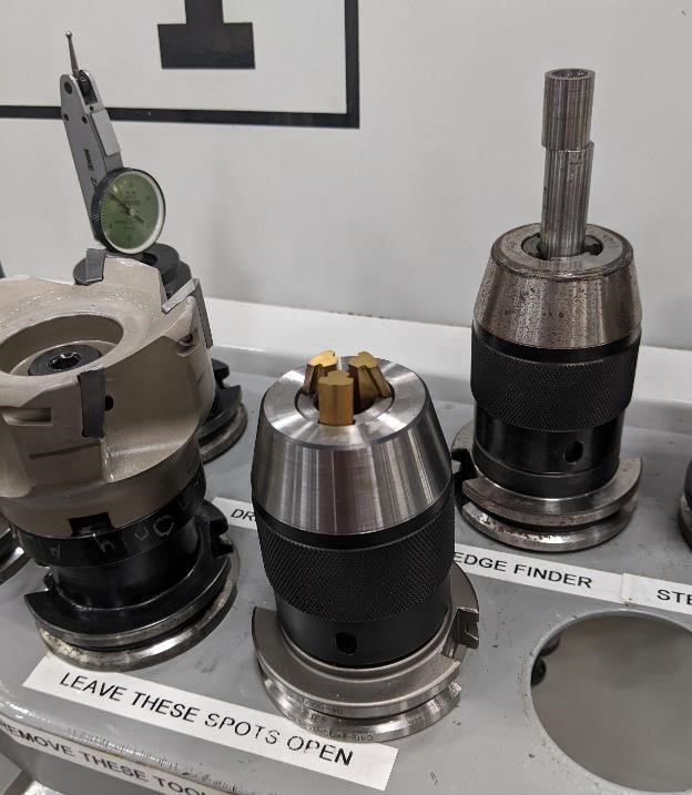
Here’s an image of the tools we used. There’s a drill chuck in the front, which we use to hold the coaxial indicator, then on the left is a dial test indicator in a holder, and the edge finder is in the back right.
Unlike the 3 axis mill, where we set up our work offsets (where the part coordinates are, where we base all of our cutting moves from), we don’t go about doing the same thing with a 5 axis mill.
Rather for 5 axis milling, everything is mostly based off of the Center of Rotation. This is the point (real, but maybe “floating” in air.) where the platters rotate around. This is where everything in our machining program is going to be based off of, and we have to know this point exactly in order to program the part and not crash the machine.
We want to make sure we know that the trunnion is aligned properly, we know our X/Y location of the trunnion, and the Z center of rotation.
Tramming and aligning the 5-axis trunnion
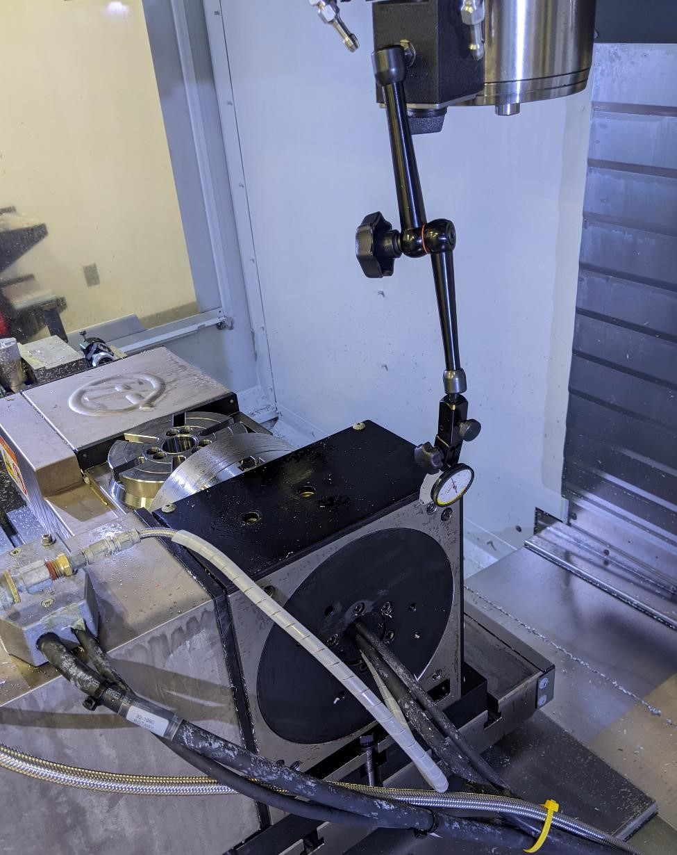
The first thing I did was to run an indicator along the back of the machine in the Y axis. This will tell me if the trunnion is properly aligned with the X/Y axis or not.
 (: width=”600” )
Run the indicator back and forth to see how much it moves. If it’s not moving, awesome. If it is (like this one did) you’ll need to loosen the two bolts holding the trunnion down to the table, and tap the trunnion into alignment.
In my case, the trunnion was rather stuck to the table, and I was having a hard time breaking it loose, so I cheated.
After breaking this loose, indicate the 5 axis trunnion back in for the X and Y axis.
The next thing is to make sure the platter is flat in relation to the machine (and perpendicular to the Z axis). You would think this would be naturally the case, but in our Haas, it’s not even close.
This is the A axis, which rotates around the X axis. It’s about 5.736 degrees off. But to figure this out…
We find this by putting a large parallel (that’s been precision ground flat and parallel and square) on the platter.
And then taking a dial test indicator and dragging it across the surface. We want to make sure that this is flat (rather, it’s perpendicular to the spindle, but for our purposes that is “flat.”)
I double checked the alignment by turning the platter (A axis) to 90 degrees and running the indicator along the face to see if there was any variation, there was about a 0.0005” of travel. While errors in 5 axis are magnified, and thus you need to take the time to very carefully dial everything in, this was good enough for government work.
Now that I’m conviced that the entire trunnion is aligned along the X and Y axes, and the platter is flat, I’m going to enter the amount (5.736) I had to change the A axis to get it level by in the G55 in Work Offsets (G55 is used for the 5axis trunnion in this machine. There’s also a vise next to the trunnion, which we use with a G54. You don’t have to do this, but it’s helpful to have a different work offset for each work holding system.)
Now when we run the machine with this G55 work offset, the platter will be flat.
On to finding the center for the X/Y axes and the center of rotation.
Finding Center of Rotation
The Center of Rotation is the point where the 5 axis trunnion will essentially revolve around in the X, Y, A and C axes. (Z is the height from the spindle home to the center of rotation).
You have to know exactly what the machine location coordinates of this point to properly 5 axis machine.
Because it’d just be too easy to walk up to the machine and find the Center of Rotation written down (or stored in the G154/G55 where it belongs), none of this information had been stored for later use by other people. Because why would that be necessary? (Lots of cursing ensued.)
I went about figuring out the center of rotation for the machine.
The below image (this is repeated as above, but this is really important to understand, so here it is again) shows the center rotation of the Haas VF4 5 axis trunnion. It’s where the gnomon is located (the red, green, blue X, Y, Z arrows in the bottom.) This is the origin point of our programmed part.
We have already set the platter (A axis) to be parallel to the table, perpendicular to the spindle, and we have set the offset. We can then move on to the next step, finding the center of the platter.
Coaxial Indicator
A coaxial indicator is a magical tool that every machinist should have in their tool box. They’re awesome.
They help find the center of bores and bosses, and can do so in just a matter of seconds if you know how to use them properly.
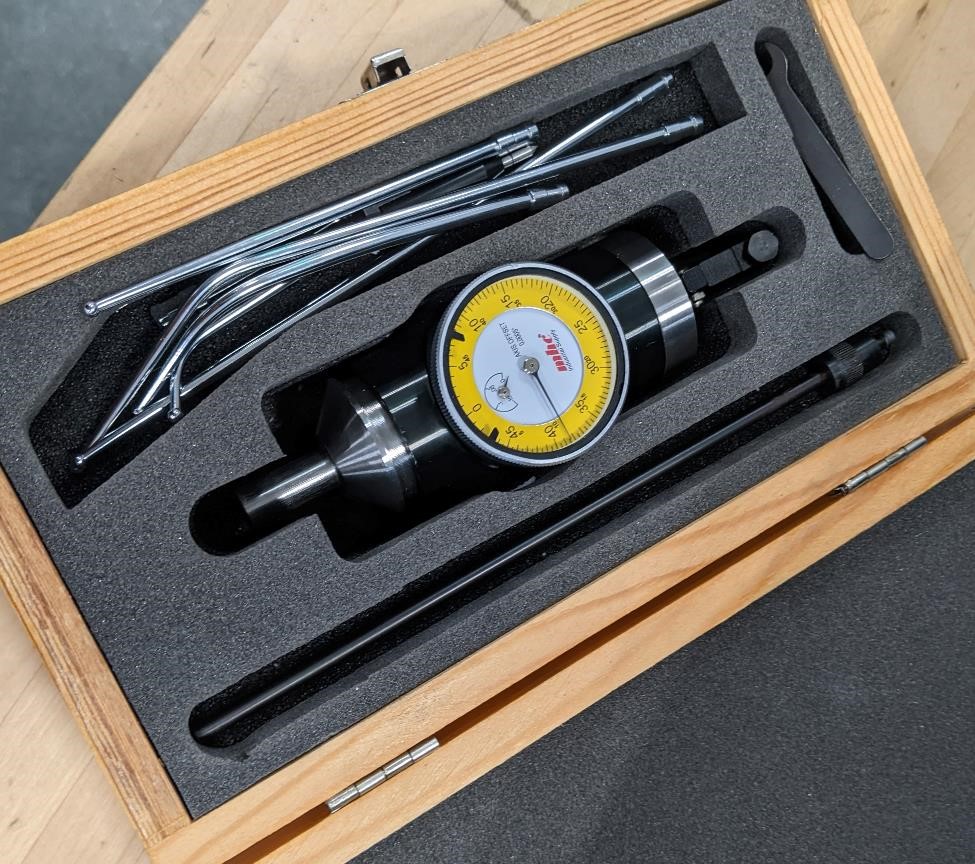
To use the Coaxial Indicator, you put a stylus in the bottom, and the handle in the side. This handle keeps the main body from turning when the spindle is on. In the image, because I’m recording, I’m using a wrench to hold the handle for me.
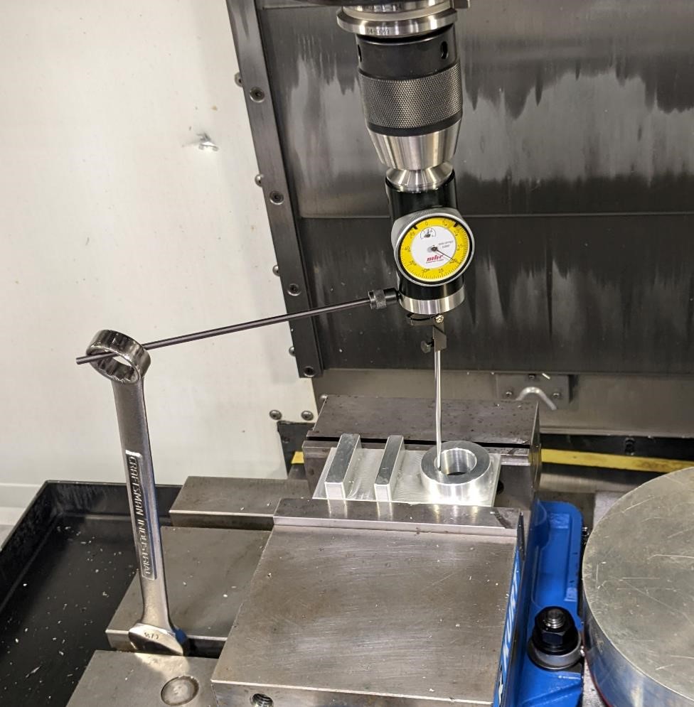
Then you roughly center the coaxial indicator (from here on out referred to as the coax) above the part and lower it down into the hole (or around the boss as the case may be).
You turn the spindle on at a slow rate, here I’m turning it at 100 rpm.
Then you move the X and Y axes slowly (at 0.001” click rate) to center the coax in the hole.
First move one axis (it doesn’t matter which one.) and you’re looking for the needle to decrease it’s fluctuations. You want the needle to move as little as possible. But moving one axis, you’ll only get to a certain point, and then the distance the needle moves will start increasing.
At this point, move back to the least movement of the needle, and change your axis to the other (if you started with X, move to Y and vice versa.) Then you again slowly move the axis until the needles fluctuations are at the lowest. You may need to switch back and forth between axes as you get closer to the zero position.
The point isn’t to get the indicator dial to read 0, it’s to get the needle to stop moving. When the needle is no longer moving, you know that the coax is centered in the hole.
I used a coaxial indicator to help find the center of the bore of the platter. This was my X0 and my Y0. This is also the center of rotation for the C axis, as it will rotate around this point in relation to the Z axis.
Below is an example of using the Coaxial Indicator. You can see how quickly you can find X and Y zero using one of these. You can’t see it in the video, but as the needle reaches it’s minimum, I’m changing to a different axis and repeating. I do this about 5 times in this video. And within a matter of seconds, I’m right at 0.
And here we’ve used it in the mill to find our X and Y zero. Again, I enter these as the Work Offsets in the G55. Right now, the X offset is: -12.3666 and Y offset is: -10.1293. These numbers are negative, as they’re coming from the machine’s home zero position. These numbers are also where the C axis home position is, and will rotate around this X/Y point.
Finding A center of rotation
Next, we have to figure out exactly where the center of rotation for the A axis is (and this relates to the Z axis as well. It’s a bit confusing, but these are related.)
There are a couple of ways of going about doing this. My favorite, and the easiest (if you’re tall enough), is to rotate the A axis to 90 degrees and -90 degrees (it’s perpendicular to the main table.) Use an edge finder, and touch off on the platter at each point (don’t forget to account for the thickness of the edge finder, we’re looking for the exact edge of the table.) Write down this Y location.
Again, do this for both 90 and -90 degrees (the platter will be vertical, facing away from you, and vertical facing towards you.) Get the Y position for each of these.
Knowing the two Y positions, subtract the larger from the smaller and divide by 2. This will be your center of rotation in relation to the platter in the Z axis. This position for the Haas VF4 with trunnion is almost exactly 2.000” inches below the face of the platter. This is where we program our part from in the CAM software. You don’t actually enter anything into the G55 work offsets if you’re planning on touching tools off by hand. However if you were using the probe and tool presetter (which make everything easier.), you would figure out the height from Z zero (spindle at home positon) to the Center of Rotation and enter this in the Z work offset. And all the tools offsets would be a positive number.
Bolt on the Fixture and align it
But we’re still not done.
We need to bolt the dovetail fixture to the platter, and align it with the X or Y axis (you don’t have to do this, but I find it’s a good practice, especially if you’re doing multiple operations. It can also help with tracking down any issues/bugs in your programs/machine setup.)
Run an indicator across the flat part of the front of the fixture and align it till it reads zero all the way across.
We’re getting closer to machining.
Tooling
This is actually a very simple part. And for this I only needed to use 2 tools.
I used a 1/4” 3 Flute, HSS end mill and a 1/4” 3 flute ball nose end mill.
But we still have to set the tools up.
Tool Height Setup.
Doing all of this, we haven’t been using our probe and tool pre-setter, because that’d be like cheating (and I figure people need to understand what’s going on before they use the new fangled digital gadgets.)
Like so many things in machining, there are multiple ways of going about doing this, and this is just one of those ways. I’ll be using the stock in the dovetail holder. This only works if you know the exact size of the stock (from the top to the base, before the dovetail. We’re ignoring the thickness of the dovetail for this.)
Put your tool in the spindle, and then using a 1-2-3 block, bring the tool till it’s below 1 inch above the stock. Then place your 1-2-3 block beside the tool, and put a small amount of pressure on it (holding it down on the stock flat as well.) Then raise the Z axis upwards until you can slide the 1-2-3 block under it. When you’ve done this, you’re now 1 inch above the top of the stock.
We then do math to figure out where the tool is in relation to our Z 0 (which is the center of rotation, under the platter) that we just discovered.)
For instance, we know that the fixture is exactly 4.5” tall (because we previously measured it.) We know our stock is exactly 3.1” tall (because we previously measured it.) and we know that we must take the height of the 1-2-3 block into account. But we also have to go to the point below the fixture, because the CoR was 2.00” below this face of the platter.
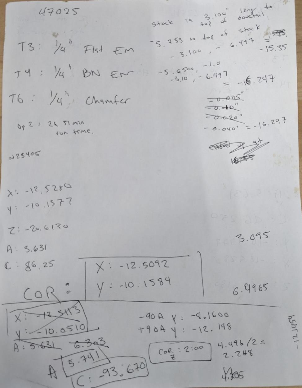
For instance, we touched our tool off on the top of the stock with 1-2-3 block. The machine distance was -4.753. We then account for the 1-2-3 block. This gives us -5.753, and then we take into account the stock size of 3.10 and subtract this, giving us -8.853. And then we add the height of the fixture, 4.5, giving us -13.353, and finally the -2.0 for the center of rotation below the platter, givins us -15.353 for the length of the tool from the spindle to our Center of Rotation Z zero.
Once we’ve done that with our tools (and by the way, we’re just using a 1/4” flat HSS 3 flute endmill and a 1/4” ball nose 3 flute HSS endmill) we’re about ready to go.
One thing I do on a new five axis part that I’m not confident about is to simply “shorten” the length of the tools, and that way the part will essentially “cut air” giving me an opportunity to fix the various mistakes I’m sure I’ve made.
Running the part
This is actually the easy part.
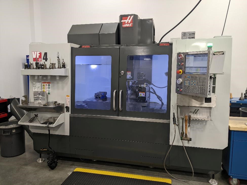
We ran this on a Haas VF4 with a five axis trunnion.
Like every other part when I’m first not sure how it’s going to work out (especially on a 5 axis.) I ran the part without the tools in the machine, just to see how the toolpaths and movement of the machine were. I’m glad I did this, as Fusion360’s post wanted to do some odd things, especially when I was trying alternative toolpath and machining techniques.
But with a 5 axis program. There’s only so much you can do after pushing the button. You have to keep an eye on your tool clearance (making sure nothing is going to crash into the trunnion) and of course on your feeds and speeds. But I’d argue there’s a bit more faith needed in the programmer and software to run a 5 axis.
So let’s push the button.
And the rough cuts…
Working on it…
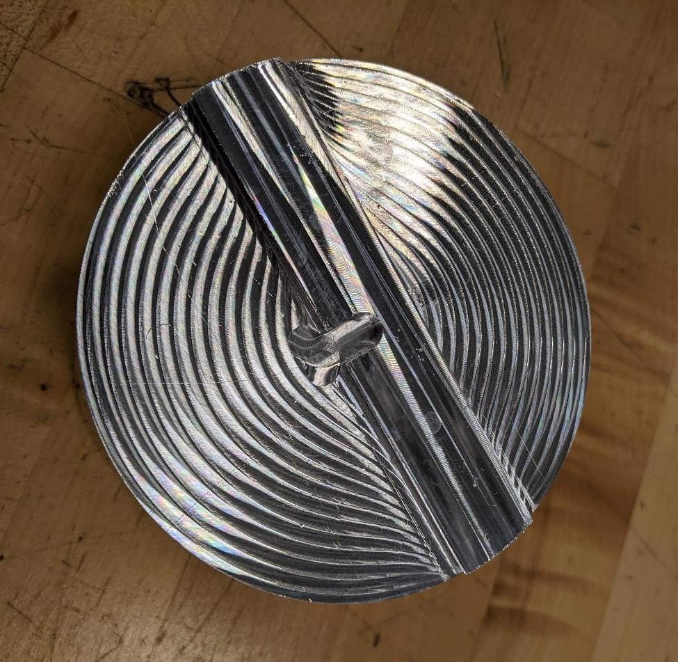
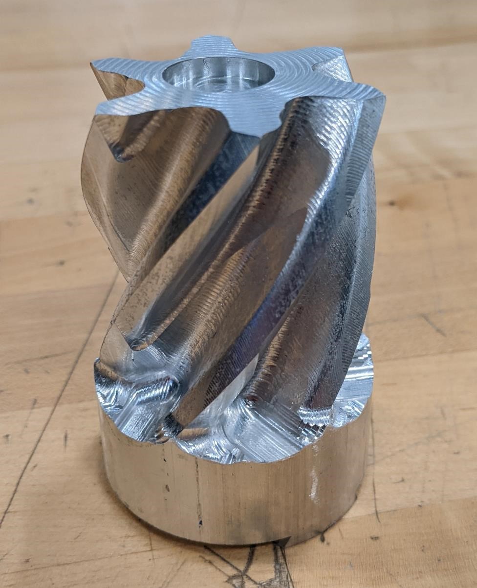
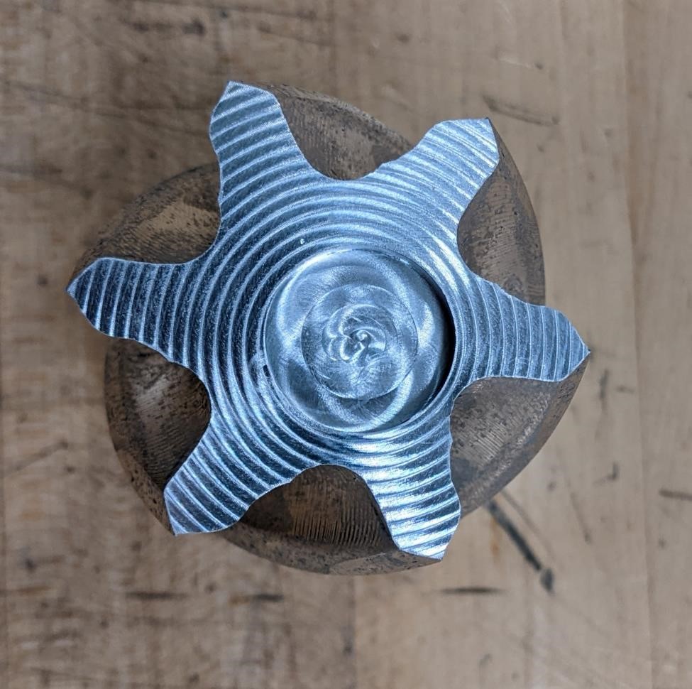
Final Part
And part finished. Less than satisfactory. I’ve done better.
And as always, my setup sheet with lots of notes and changes.
Issues
Not a big fan of our Haas VF4 with a 5 axis trunnion.
We had a couple of problems with this trunnion. I checked the flatness of the platter off of an old value, and it was almost perfectly the same. The next day when I walked up to the machine, it said it was at this location, but it was obvious that the platter wasn’t flat. I essentially reset the machine and tried again, and it was closer to correct, but still off. I had another instructor check it for me, thinking that I was doing it wrong. He did get a different number, which was off by an entire degree.
However, we rotated the platter about the A axis and back to where A0 should have been, and it was off again.
We found A0 again, and it was almost identical to what I had previously used.
But the fact that there was so much unpredictability and a lack of repeatability was kind of frustrating (it’s FabAcademy, what do you expect?). And simply tracking this issue down took a good hour.
And it took way too long to realize that the trunnion was not aligned properly with the X/Y axis. There was a twist to it. Totally my fault, I should have checked it immediately. Sigh....
Fusion360 issues.
Fusion360 also threw a number of hurdles in my way.
One was rather simple, and it was my fault for not noticing it quicker. Fusion360’s post for the Haas next generation car of tomorrow post-apocalyptic controller defaults to have DWO (Dynamic Work Offsets) to on, and TCPC (tool tip control point or something) as well. Having these as enabled in my post caused a number of issues.
Finally, there are a lot of bugs in the Fusion360 rotary axis, and it’s obvious that it wasn’t quite designed for a 5 axis setup.
Less than happy with the part.
The part came out pretty bad. I’m really not happy with it.
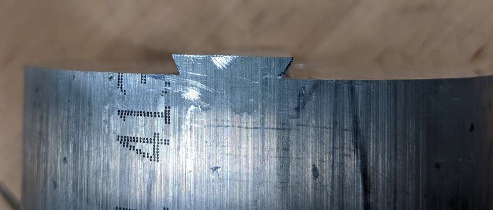
I had planned a bore on the top of the part in order to have a bearing in the top, but this was stupidly off-center. I have an idea what happened, but I need to confirm it. The obvious issue seems to be that the A axis is not as level as it should have been. The second reason could be an off center X and Y, though I think this is somewhat unlikely. The third could be that the stock/fixture is offset from the true center of X/Y rotation. Possible, but again, I think it’s a bit unlikely. But if given time, I’ll start trying to track these problems down.
Tooling offsets seem to be off, not like 0.005” or 0.010”, but like 0.150”. I’m going to have to look at these as well.
(Update: and I found it, the Y axis was literally something like 0.103” off. I corrected this, only to find out that the trunnion was twisted as well. This has been quite the journey.)
References:
Rodney Owens, because he’s awesome, and helped me more than he needed too with this. And I know he enjoyed me slagging on Fusion360 for once.
Look towards your local machining instructional facility. ie, your local community college for more information.
And Youtube.