8a. Group Project - CNC Machine
Week 7 - 3/9/22
The group project for this week was to characterize the CNC machine.
Unfortunately, we had a very limited amount of time on the Shopbot CNC Router, as we were using the one at the Charlotte Latin FabLab. As such, we decided to use a CNC Mill that we did have access too at CPCC.
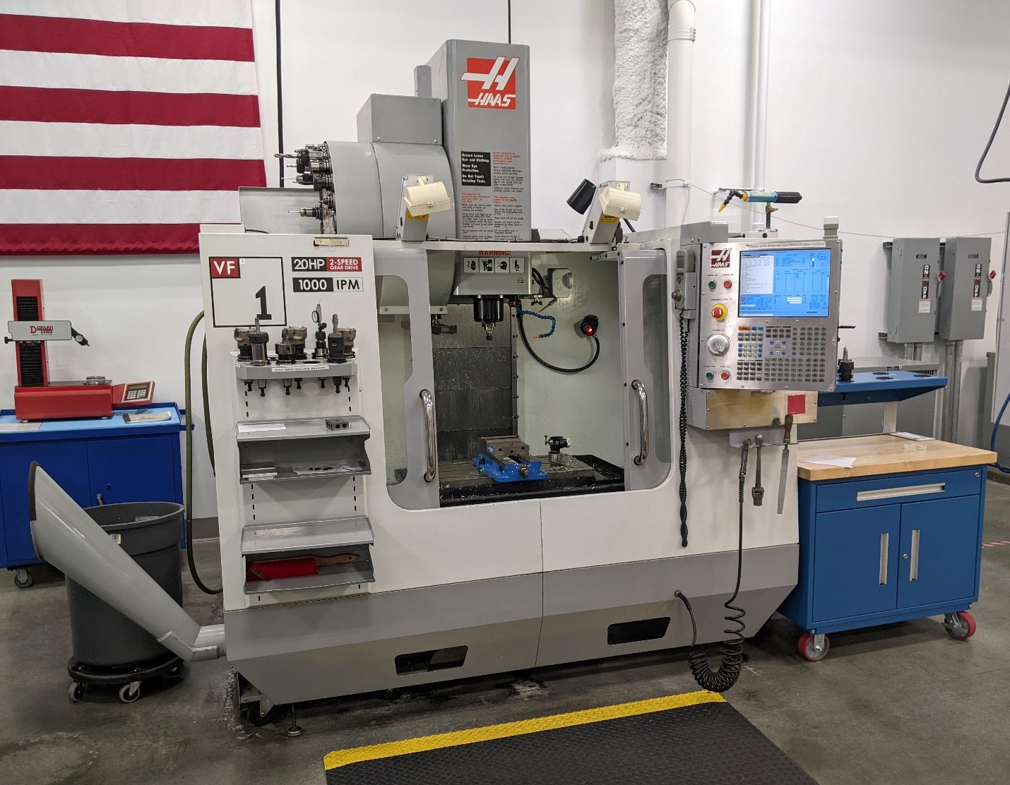
Haas VF1 Mill
One machine we did have access too was a Haas VF1 CNC milling center located in CPCC’s Computer Integrated Machining Lab.
The Design
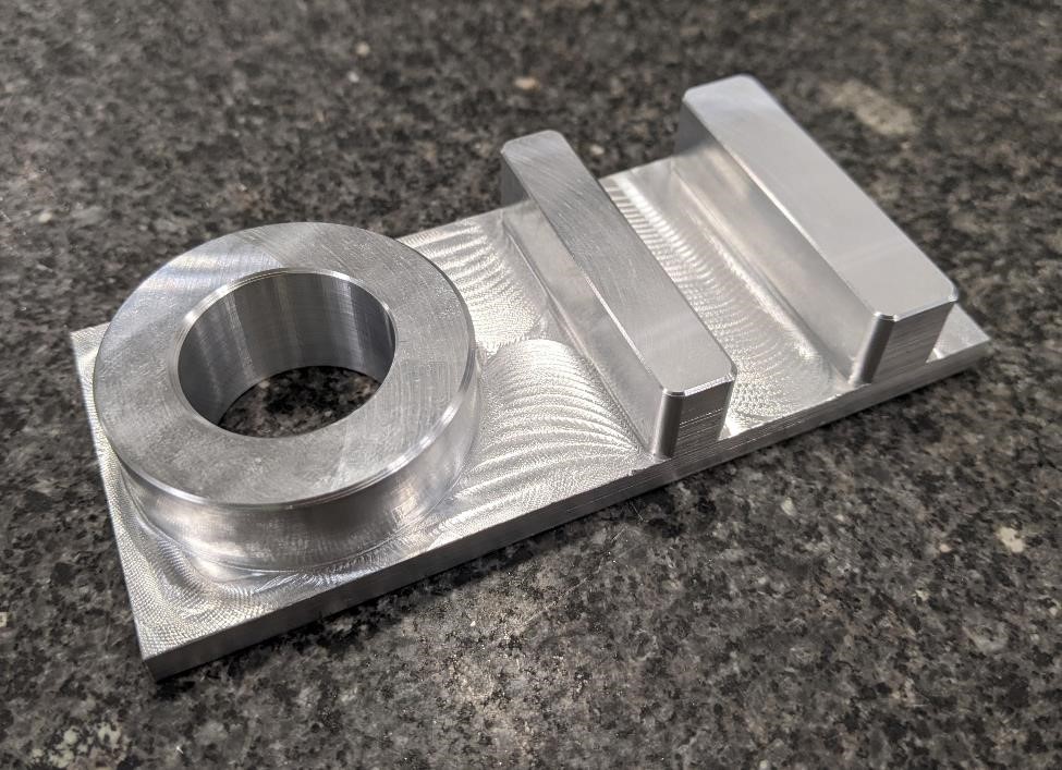
We made a quick and simple part that would look at different aspects of machining on the Haas.
This part is simple, yet with just a few features, it can tell you a lot about how a machine is operating.
We’ll make a bore, a boss, a slot, and two plateaus. With these features, we can get an idea about the mill’s accuracy, tolerance, and other information.
We’re using Fusion 360 for CAD and CAM.
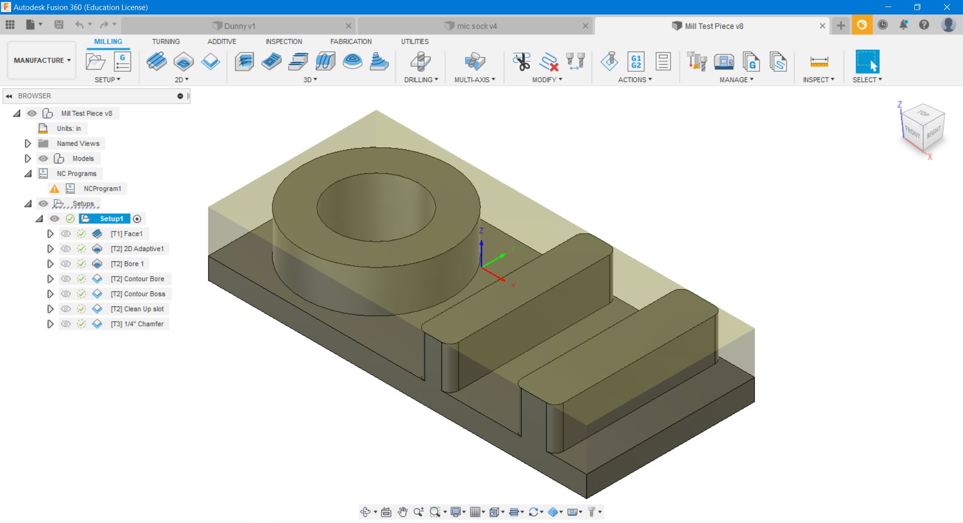
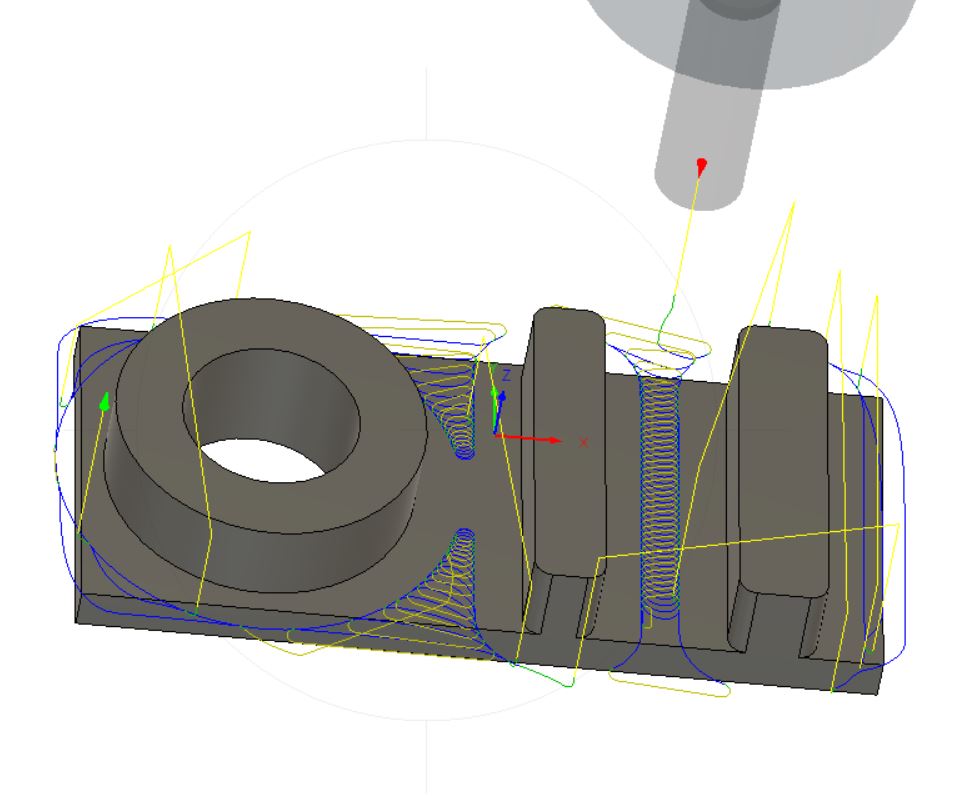
Here we see the adaptive tool path that we’ll be using to remove most of the material.
Speeds and Feeds
Check out this excellent video on feeds and speeds created by Haas CNC’s Mark Terryberry: https://youtu.be/zzzIpC39WUg
Speeds and Feeds is a quick colloquialism describing the spindle speed of the cutting tool, and the feed rate of the tool moving through the cutting material.
A machinist rant on Speeds and Feeds.
Speeds and feeds are very important when machining, and especially become more important the tougher the material you’re cutting becomes. However, speeds and feeds is just one factor that has to be considered. They are a starting point. They are not written in stone. They can and should be changed based on a number of factors.
Other factors that must be considered include:
- How well is the part held? (Is it barely held, is it firmly held?)
- How long is the tool stickout? (is it a long tool, unsupported, or short and stubby?)
- How well is the tool held?
- How rigid is the machine? (cnc wood router or milling center?)
- What type of machining strategy are you using? (High feed, high speed, slotting, boring?)
- What is the depth of cut? (how deep is the tool cutting?)
- What is the radial depth of cut? (depth of side cutting)
- Are you running coolant, if so, how well does it hit the cutting surfaces?
- And other variables that might come into play.
Each one of these affects what speed and feeds to run. Each one must be considered when choosing the RPM to spin the tool, and the feed rate of the cutting tool through the material.
Further, as you typically choose a Surface Feet per Minute to base your speeds and feeds on, you need to know how this information was chosen. Was it based on a chart made in the 1980’s or is the SFM calcuation coming from the tool supplier?
Speeds and feeds are just a starting point. No matter what you calculate, I can almost guarantee that when you machine the part, your speeds and feeds can be optimizied for better tool life and a better surface finish, and possibly a faster machining time (but sometimes you’ve got to run slower not to break your tools).
In this case, we ran the part conservatively as I was running a High Speed Steel endmill without coolant (in order to get a better video). I did run coolant on the boring operation, but that was merely for chip evacuation (recutting chips will quickly dull the tool, and can provide a bad surface finish).
For the majority of the part, we used a 1/2” 3 flute HSS endmill. We ran at 60 inches per minute at 7000 RPM. This was about 900 SFM. I had a radial stepover of about 0.050”, and a chipload of about 0.005” using a high feed, adaptive/dynamic toolpath cutting strategy with finishing contour passes.
Setup
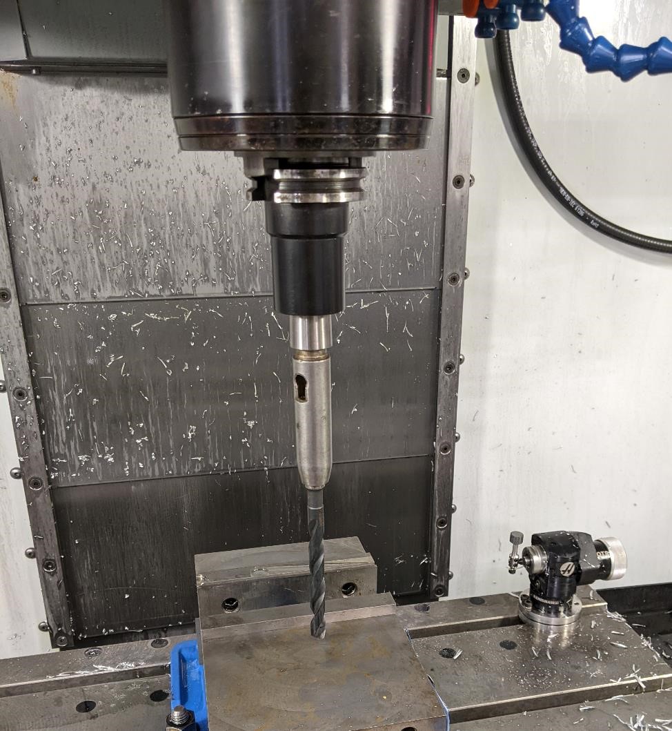
Then it’s time to cut our stock, gather our tools and take it over to the machine…
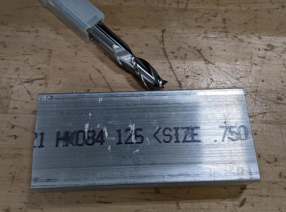
We’re cutting this off of a chunk of 6061 Aluminum that is 4.5” x 2” x 0.5.” It’s sitting next to a 0.5” diameter, 3 flute HSS endmill.
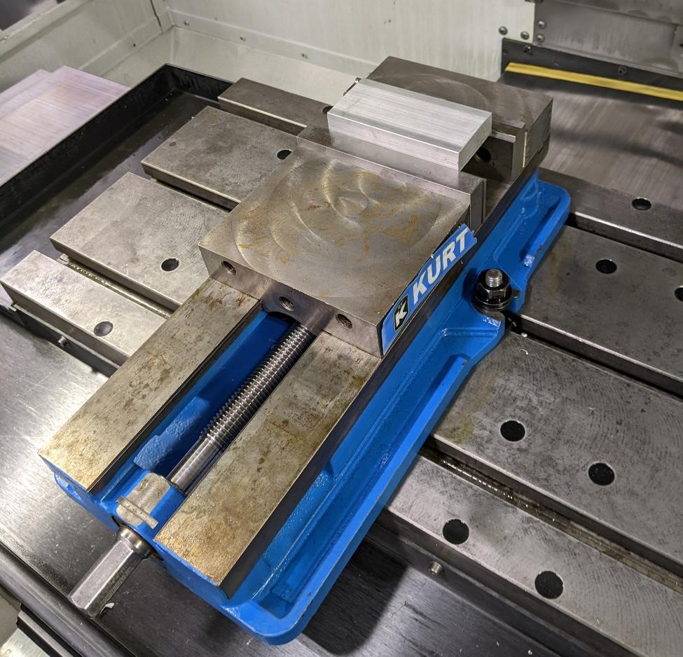
We need a way to hold the stock, so we put it under two parallels and hold it in a vise.
When you’re starting your setup, it’s incredilby important to have a setup sheet. It doesn’t have to be professional, it doesn’t have to look nice. But you need something that has key details about the part you’re going to make, the tools you’ll make it with, and information about how you’re holding it and what machine you’ll be using.
The below is Garrett’s quick and dirty setup sheet. Even though it’s a decent setup sheet, looking at it now I realized he left out a key piece of information, where is the “part zero,” that is, where do I tell the machine to base all of it’s coordinates off of when it’s interacting with the stock? In this case, we went off the top, center of the stock (which on these projects is the norm for him, and he forgot to add it to the setup sheet.)
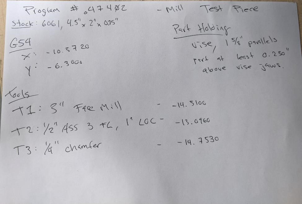
Information included in the setup sheet contains the following:
- The Part Name - “Mill Test Piece”
- The Program number - o47402
- Stock material and size: AL 6061, 4.5” x 2” x 0.5”
- Where the part is located from - top of stock, center of stock.
- How we’ll be holding the part - on 1 5/8” parallels in a vise
- How we hold it, ie, clearance to avoid crashing.
- What tools we’ll be using and their numbers
- T1: 3” Face Mill
- T2: 1/2”, High Speed Steel, 3 flute, 1” length of cut end mill.
- T3: 1/4” 90 degree (45) chamfer mill.
- The above also includes the length of the tools (in this case, a negative number from the Z zero position of the machine.)
- and the “G54,” the location of where the part is located in relation to the machine.
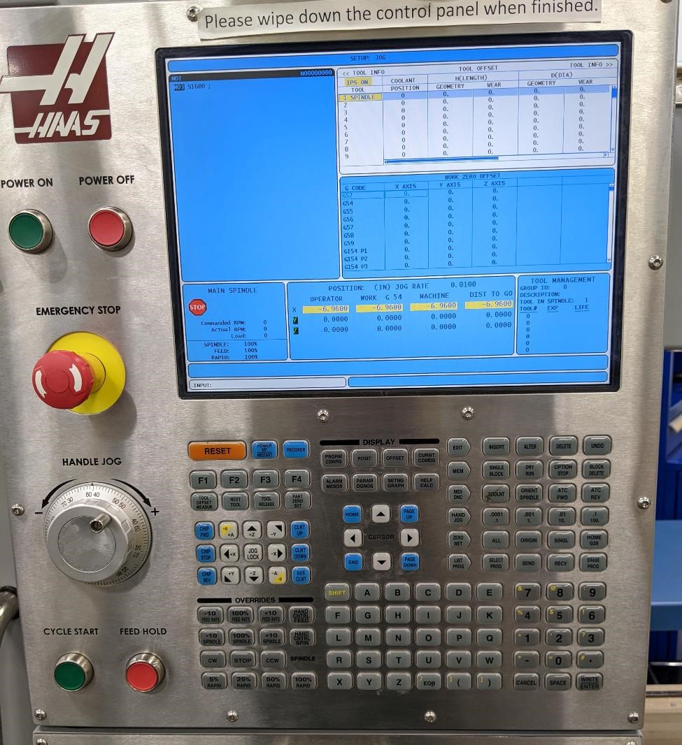
Next we need to tell the machine where that part zero is. The X and Y location that we’ll be basing all the machine movements off of.
We used an edge finder to touch the side of the stock. In the case of going off the center of stock, we can touch each side in both axes (X and Y) and just divide by two to get the center.
Once we’ve figured out where these locations are, we enter them into the machines controller.
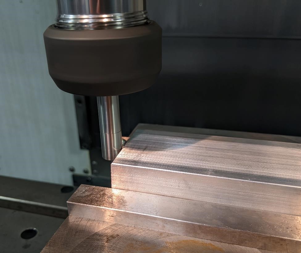
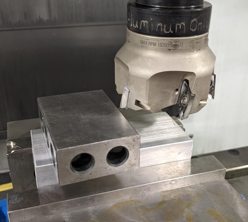
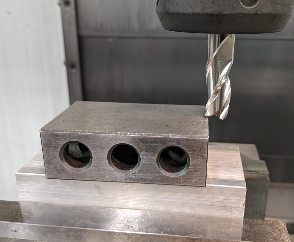
Next we need to tell the machine the length of our tools in relation to where the top of the stock is. This is the tool touchoff.
Here we’re using a “1-2-3” block (it’s a precision piece of steel ground to have dimensions of 1 inch by 2 inches, by 3 inches) placed on top of the aluminum stock to help touch off.
But we don’t bring the tool down to the 123 block. The block is hardened steel, it will break the tool.
Instead, with the 123 block out of the way, we move the tool down closer to the aluminum, and then while putting very gentle pressure on the 123 block, pushing it against the tool, we slowly raise the tool. And when the 123 block slips underneath the tool, then we know we’re 1 inch above the part.
We don’t want to forget to account for this 1 inch when we’re getting ready to cut. But for now, we can leave it, and that way when we can test the part in air to make sure it doesn’t behave in unexpected ways.
Later on, remember to add this 1 inch to your tool height offset.
Cutting
We have a video, it’ll be uploaded soon.
It only took about 4 minutes to make the entire part, and this was with very conservative feeds and speeds, and with unoptimized tool paths.
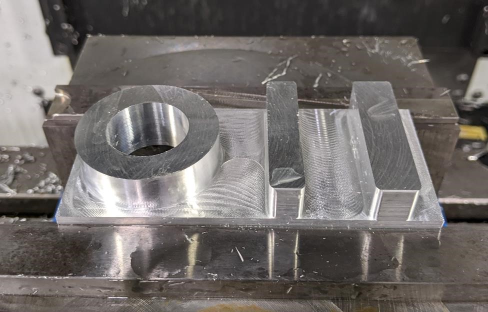
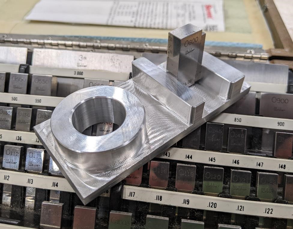
Inspection
After we’ve manufactured the part, it’s time to see what it actually measures.
The width of the first step on the right side was designed as a 0.500” width. Here it checks out to be about 0.5025”.
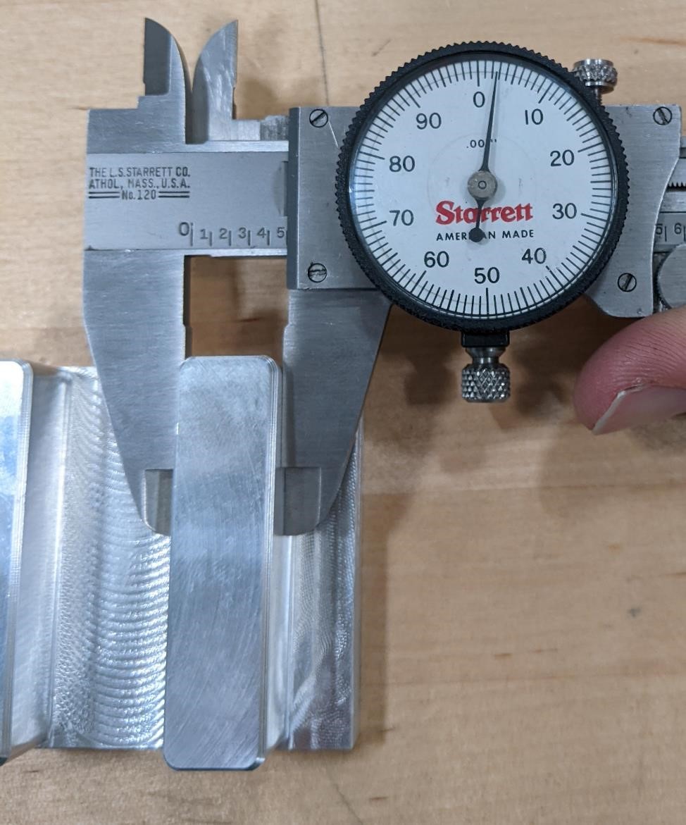
The next step was designed as 0.400”. Our calipers measured it to be 0.4025”. Again, 0.0025 oversized.
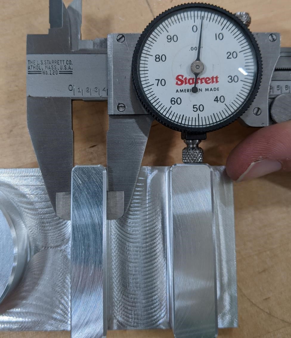
The distance between the outside edges of the steps was supposed to be 1.650” It measured as 1.6525” (starting to see a pattern here?)
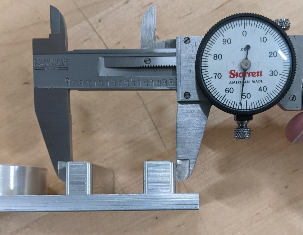
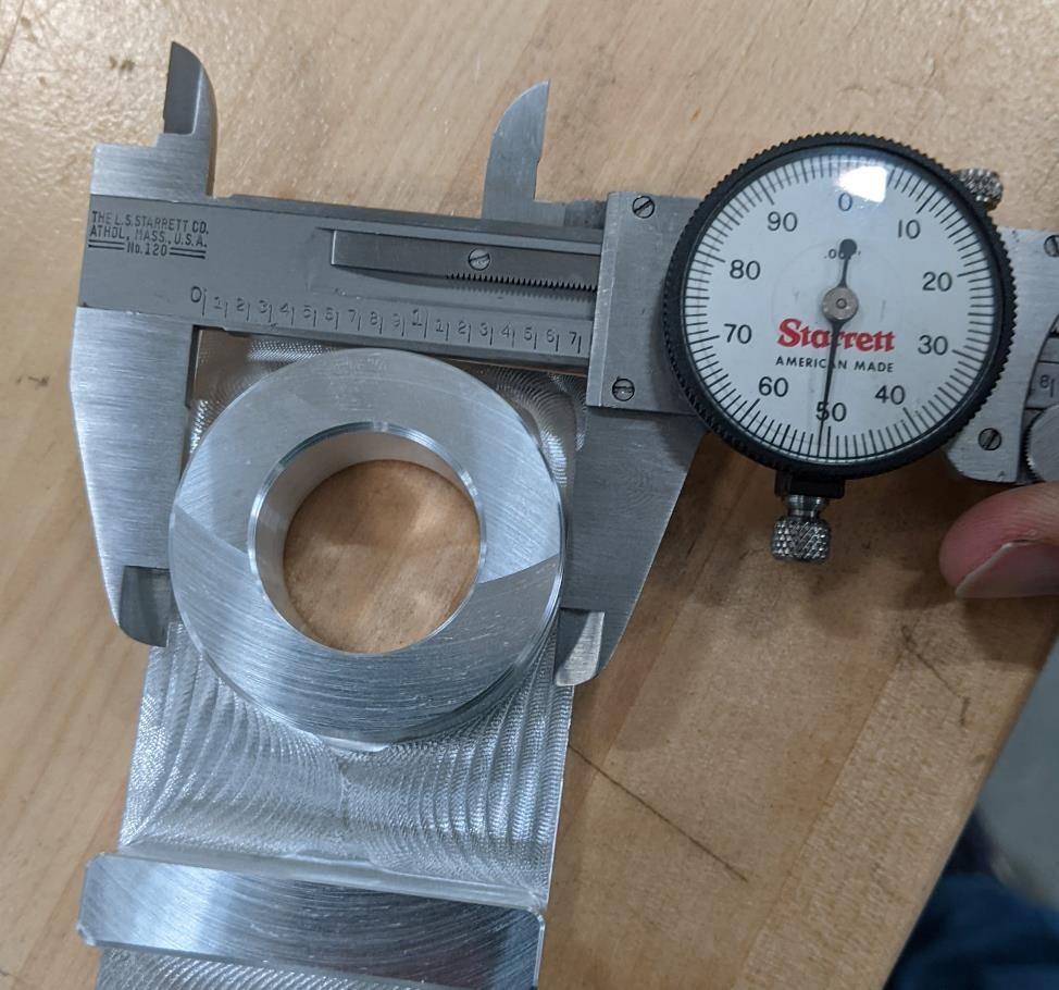
The outside boss was designed as 1.750” and checked out as 1.751”
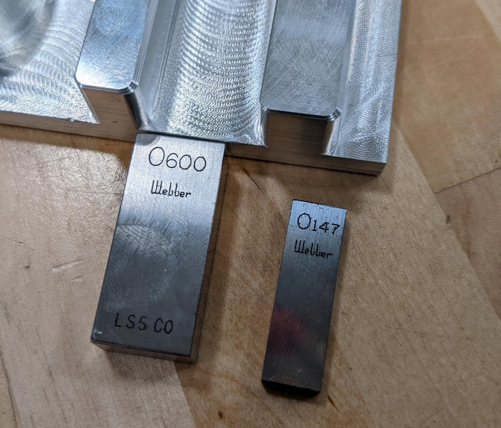
Then we can use gage blocks to check the slot width.
The slot width was supposed to be 0.750” wide. Here, we could only fit a wrung pair of gage blocks of 0.747” to the bottom and length of the slot. Indicating the slot is 0.003” undersized.
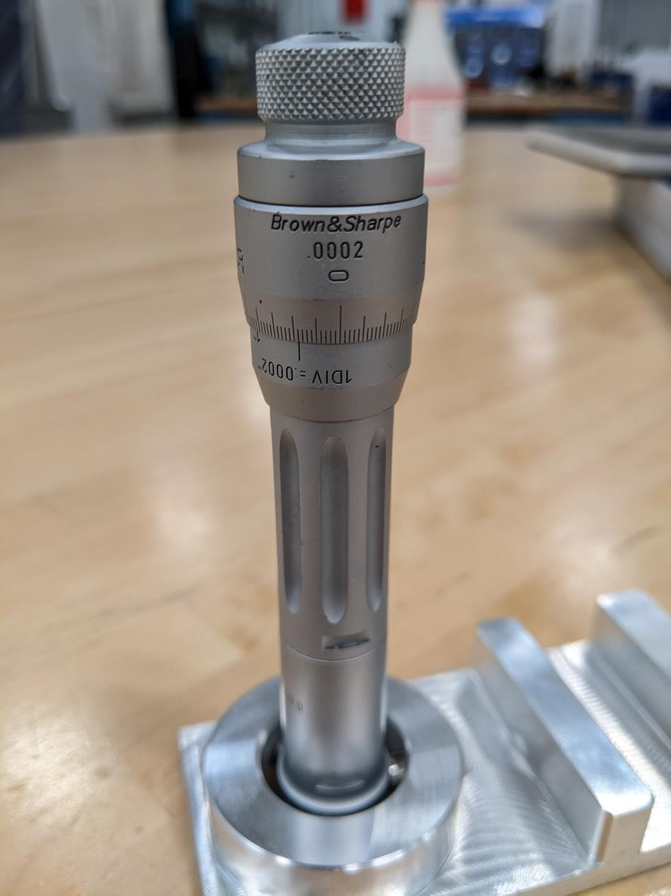
And we use an intrimik (bore micrometer, tri-mike, holtest, etc.) to check the diameter of the bore.
In this case, it seems to have been 0.0018” (0.045mm) too small for the 1.0” targeted bore size.
AND THIS IS WHY OFFSETS EXIST.
This means you Shopbot.
Checking Runout
It’s very difficult to measure spindle runout to an exacting measure without something like an autocollimator or other specialized equipment.
It’s much easier to measure tool and tool holder runout.
It should also be noted that the setup of your tools and toolholders is generally what causes the largest amount of runout. For example…
Did someone say runout?
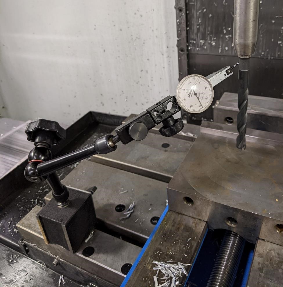
The first image is the jankiest tool holding setup that we could come up with. It’s a CAT40 tool holder to a Morse Taper #3 Adapter, with a really horrible, completely messed up Morse Taper 2 to 3 adapter, with a very old, beaten up taper drill bit.
It’s runout was so bad that it pegged the Mitutoyo 0.0001” indicator (granted, the travel on this was only about 0.009”).
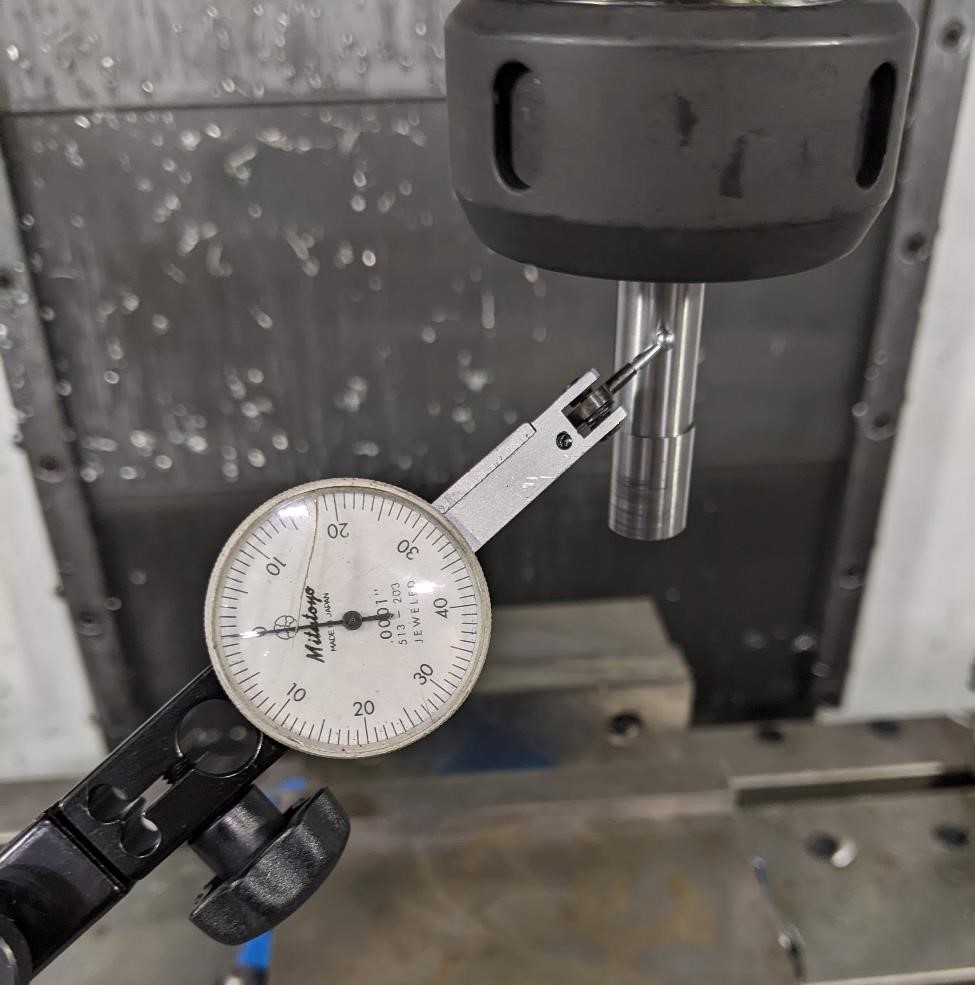
The next setup was just a normal edge finder (0.50” ground to a well finished diameter) in a fairly new CAT 40, ER32 0.50” Collet. The runout on this was barely noticeable, somewhere under 0.0001.”
Which is to say, you can’t do much about spindle runout; but you can do a lot about your tool and tool holding and the runout caused by these factors.
And with that, we determined that our mill does in fact make a big mess that someone has to clean up. Cori was volunteered.