8. Computer controlled machining
Week 7 - 3/9/22
This week we get to play with a very large dangerous cutting tool.
Whatcha Going to make?

Unfortunately, I had run out of creative gas, and I couldn’t come up with something that I thought was neat, cool, nifty, useful, dangerous, etc. I had no good ideas on what I should make.
After talking to a ton of people, Cori, David, Adam, Denny, etc, I had heard a number of great ideas on what to make. However, none of them worked for me.
Making a toolbox would be cool, but to do it right, would take more time than I knew I had to put into it. The time constraint also affected this decision, which because of lack of access to a shopbot of adequite size, plus the amount of time that I would have to use the shopbot being shared with a number of others, meant I had to get an idea and make decisions fast, or run completely out of time to get anything done.
But thankfully, earlier in the semester, while looking Neil was sharing other students projects, a student’s weekly assignment caught my eye. It took me a while to track down the link, but I finally found it:
Ani Liu’s website on How to Make (almost) Anything
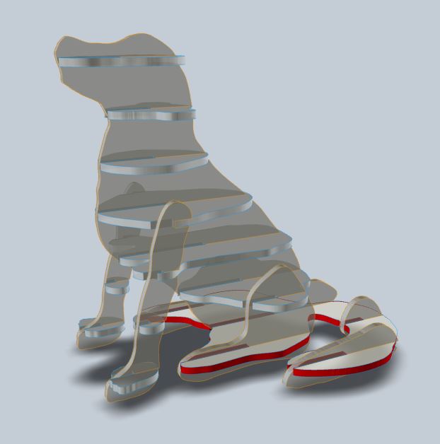
In which her week 2 project, computer controlled cutting, was a Corgi made out of slices of cardboard. (Ani’s the one who made the PCB of Neil’s Face.)
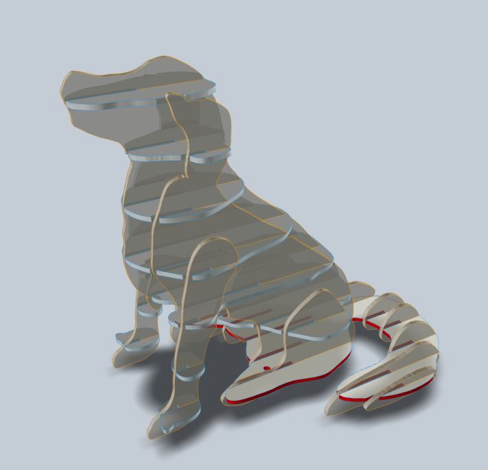
Yep, I’m going to make me one of those, but of a Golden Retriever.
Software and 3d Modelling
Unfortunately, for like the umpteenth time already during this class, somebody was doing something very cool with Rhino, and it’s one of the few programs I don’t have access too.
In the above link, Ani was using Rhino to make contour lines of a 3d model that she had grabbed off the internet of a Corgi.
No Good Dogs
Well, I didn’t have access to Rhino, or a 3d scanner that would take a full size 3d scan of my dog, Willie Nelson. The GOM scanner is great, but Willie Nelson isn’t sitting still on a 12” round plate for 2 hours as a blue light shines at him.
(And as an aside, I had even asked the entire class if anyone knew of such a scanner that would work well with dogs. The only solution I recall was of large array of cameras controlled by Raspberry Pi’s, which is what I would have liked to create, but it is very cost prohibitive.)
Unfortunately, I couldn’t create a 3d scanned model of my dog, but instead I would have to search the wilds of the internet.
And how disappointed I was. There are no good, free STL’s or other models of Golden Retreivers on the Internet. This is an injustice. This shall not stand.
But in the mean time…
Testing Slicer (not that type of slicer)
I remember a student had created a project in which the took a 3d model, and had broken it down along contour lines to create a simple 3d model based on the inherent shape of the model. They had used it in one of the early weeks (perhaps CAD week) and they had mentioned this software called “Slicer” for Fusion 360. (And thankfully I took note of this, and wrote it down so that I could find it later.)
Sadly this softwareseems to be related to an older version of Fusion360 as a sort of add-on software, and it doesn’t seem to be supported anymore, which is a shame, as this is some very cool software.
Testing out my slicer software as you do when you use any new printer or slicing software:
(because I had too.)
But again, you feed this software an .stl or .obj file, and it gives you the ability to “slice” the model with different variety of styles and options. I believe some of the features are not quite working, but I think this software will work well enough for my use.
Back to the lack of 3d models of Golden Retrievers
Taking matters into my own hand, I tried to see if I could create a model myself.
I had zero expectations, and honestly figured I’d try this for an hour, quit, and just go buy a 3d model of a golden retriever for $10 or whatever they sell for. At least I can say I tried before I give them my money.
In the second week, when we focused on CAD, I didn’t document every single software I tried. Some of them were such failures, or I just didn’t want to bother, that I skipped them.
One that I should have, but honestly had just forgotten about it until this week was a 3d modelling/sculpting program called ZBrush Core (or Mini, or Core mini, or.. or.. They keep changing the name/branding.)
I had spent about 2 hours on this software originally, trying to find tutorial videos (all the tutorial videos on Zbrush’s website focus on their full featured software, and while there is a lot of overlap, there’s a noticeable difference in capabilities and ease of use.)
The video tutorials “How to start in Zbrush” that I watched are here: https://pixologic.com/zclassroom/course/getting-started
I’m used to learning some fairly complex software, and usually the hard part is getting the software to do what you want it too. You may have to lie to it, figure out the right order of operations, or any other little trick. But I can usually get it to do what I want.
Zbrush Mini (or whatever it’s called today.) is the opposite. The software is fairly easy to grasp and start using immediately… But because of this, I realized very quickly that the trick to using scultping software is to have artistic skills. Something that I don’t have.
So after spending about an hour in tutorials, and an hour or so learning that this software isn’t going to do me any good until I learn how to be an artist, I stopped using it and never looked back.
So I tried again.
Zbursh CoreMinTiny202twoUpVersion31 (I’m not changing that typo)
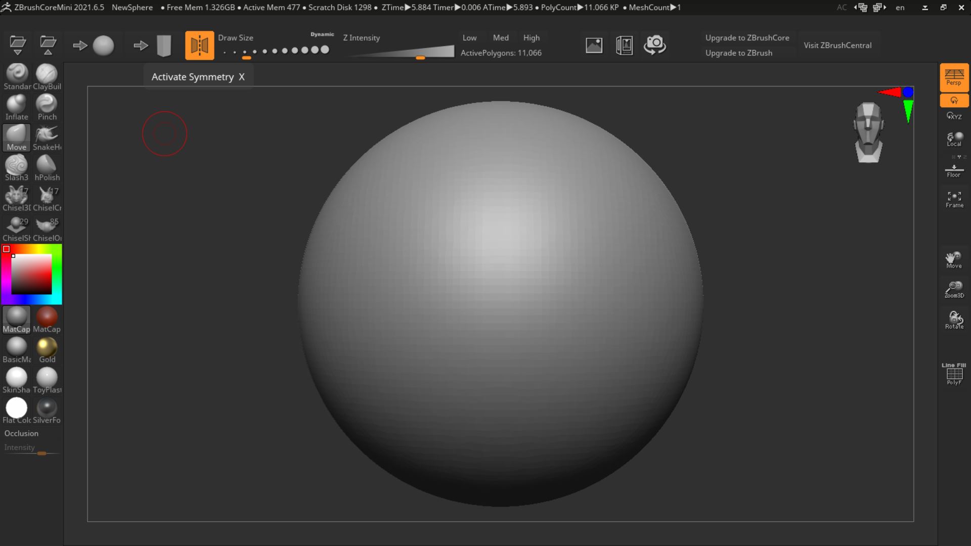
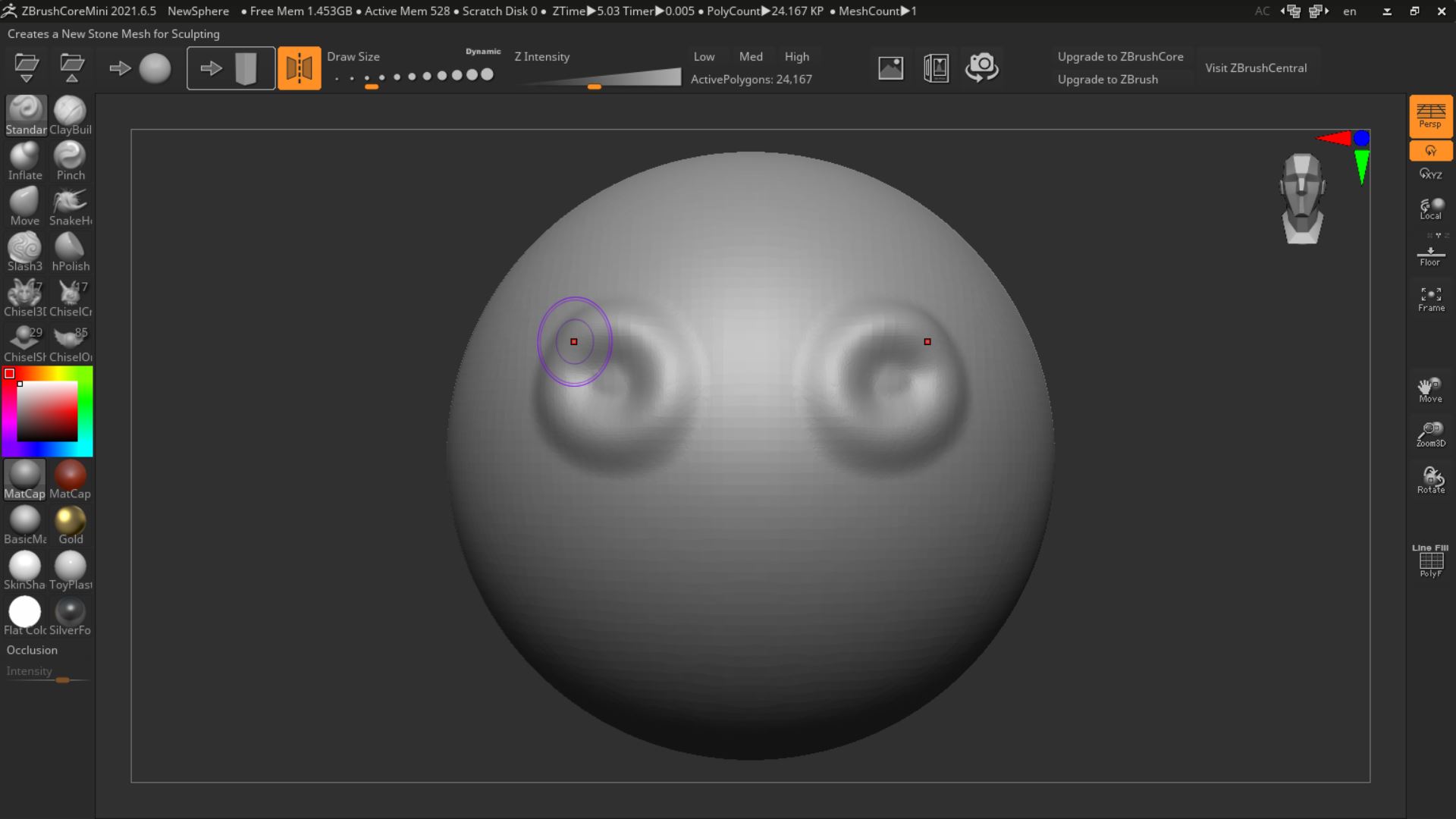
When you first open up Zbrush, you’re faced with a perfect sphere. Oh my goodness. How am I going to turn that thing into a dog?
But luckily, Zbrush is quite easy to use (but that doesn’t mean you’re going to get good results. Like all art, it’s up to you to make good art, not your tools.)
Being a freeform scultping tool, this is essentially just molding a ball of clay (almost literally, the tools are often named similiar to real ceramic working tools.)
Zbrush Controls
The main things to focus on are the sculpting tools on the left menu bar:
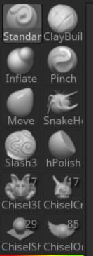
The tools you’ll probably use the most are the “standard” tool which allows you to add and subtract clay, as well as the “move” tool which allows you to “massage” the clay and move it around. But there are other tools that are very handy.
“Polish” lets you smooth out bumps and imperfections in your model.
“Inflate” makes it easier to add such features at tails, muzzles, etc.
“Slash3d” lets you carve fairly deep lines in your model, helping with creating creases and other delineations necessary to good sculpting.
The other tools are more specialized, and I didn’t find I needed them (or know how to use them.)
But the feature that is probably the most important aspect of using Zbrush effectively is the tool option at the top center of the screen:

These tools allow you to control the size of the tool, ie, the amount of area/clay that is affected by the command that you’re using. And the intensity affects how much the command will impact your sculpting. A small amount and you’ll barely notice a difference, a large amount and your entire model is destroyed in a second.
However, it’s this feature that allows the modeller a lot of control over what they can do to the model. It took me too long to learn this lesson, but once I did, I found that my ability to at least a dog-like shape versus a thing, increased dramatically.
Then you also have an option (highlighted in orange in the above image) that is the “symmetry” option. When this is selected anything you model is copied symmetrically on the other side of the part. It makes sculpting faces, bodies, etc. half as easy. And you can turn it off if you need non-symmetric features, like tails for instance.
And then all you have to do is start using the tools to sculpt your ball of clay.
And after a few hours…
(That’s my ode to “Hello World” tutorials. Now you should be able to go out and program this AI to drive your car!)
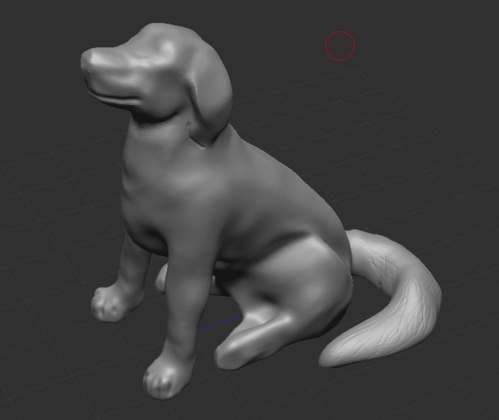
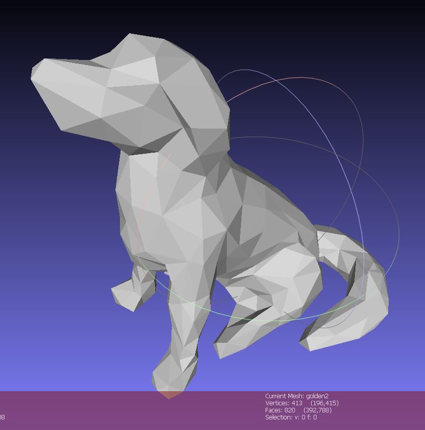
That model is not very good, but thankfully, it’s good enough for my use case. Being that I’m literally going to just be taking small slices out of the entire model, I just needed a rough shape outline to create a slicer file. I don’t have to focus on the fine features and such (thankfully!)
So now I have a rough dog-like shape that I can use for the Slicer.
And I also used Meshlab
Zbrush outputs an .obj file, and while the Slicer for Fusion360 software will take .obj files as input (though I didn’t know this until after I converted the model) I had opened it up in Meshlab to decimate the number of faces and vertices in the model. It had gotten quite large (I think it was like 400,000 vertices, 800,000 faces. Which is way too many. The file was 41mb.)
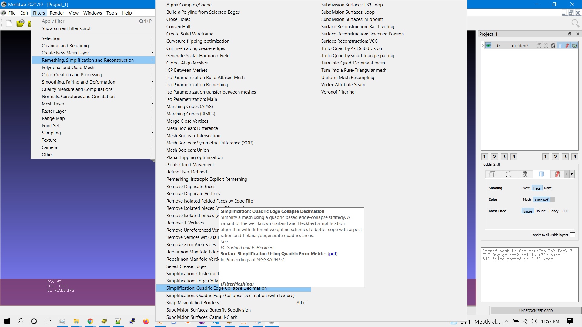
I used the “Simplification: Quadric Edge Collapse Decimation” to shrink the number of faces, which affects the file size as well.
In Meshlab, go too:
Filters -> Remeshing, Simplification and Reconstruction -> Simplification: Quadric Edge Collapse Decimation
You don’t have to do much with this filter. It gives you a number of options, but it usually defaults to halve the vertices/faces, and if you click okay, it will cut the model faces about in half (it tries to get close to the number you give it).
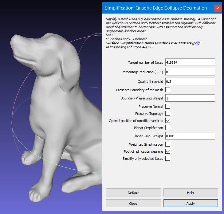
I used this a number of times just to see if I could get to a “low poly” model. But I also kept a high resolution model that is still 100,000 faces.
And back to Slicer for Fusion 360
Slicer is very cool software. I’m not aware of anything else like it, and for such a relatively small, niche piece of software, it’s well thought out and surprisingly full featured and polished.
With Slicer, it accepts STL or OBJ files. I imported the model I had created from Zbrush. The Zbrush STL after converting (as noted above) was something like a hefty 400,000 faces and 40mb file. This is where shrinking the number of faces makes Slicer perform better.
Set up your stock size
The next thing is set up the piece of material you’ll be making this part out of. You don’t necessarily have to do this, but it makes sense to go ahead and get an idea of what you’ll be working with for later.
In the manufacturing settings page, (click on the manufaturing settings box, and then click on the pencil icon on the left.) it had a number of paper settings. I made a setting for a piece of 8’ x 4’ plywood.
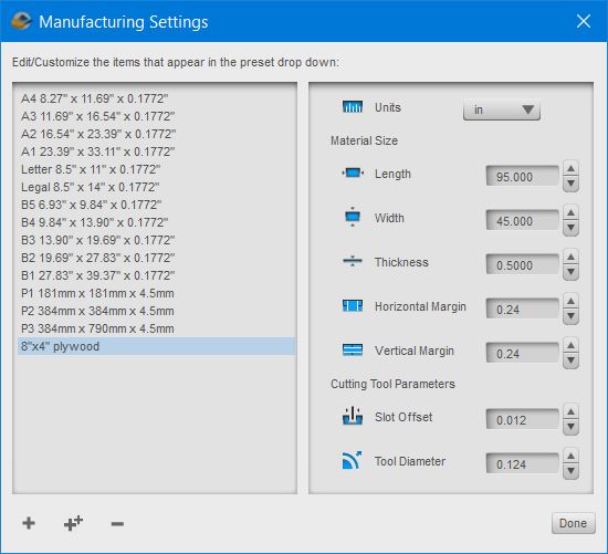
Note that in the above image, there’s a key mistake I made that I would pay for later. And it’s quite the amateur mistake. I put the wrong tool diameter size in (and no, it’s not the 0.124” versus 0.125”; I very often lie to the machine about the real size of tools) and we would be using a 0.250” bit. This affected the size of the dogbones, and made me manually recreate them later.
Click the “Plus” icon in the bottom of this window to create a new material type. Then enter your dimensions and other information.
In this case, I entered the units (inches), the length and width of the plywood (converted to inches for the 8’ x 4’ plywood).
Include the thickness of your part, this is very important for the size of your notches.
Enter the tool you plan on using (I believe it uses this for dogbones clearance size) and an offset if you wish.
Setting up the interlocking pieces
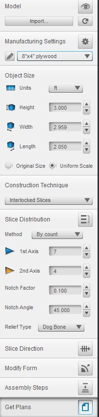
Once you import the file and set the size of your material, you also need to set the size of your model as well. For my model, I wanted it to be 3 feet tall. In the main menu on the left, I set units to feet, checkted the “Uniform Scale” size and let it do the rest.
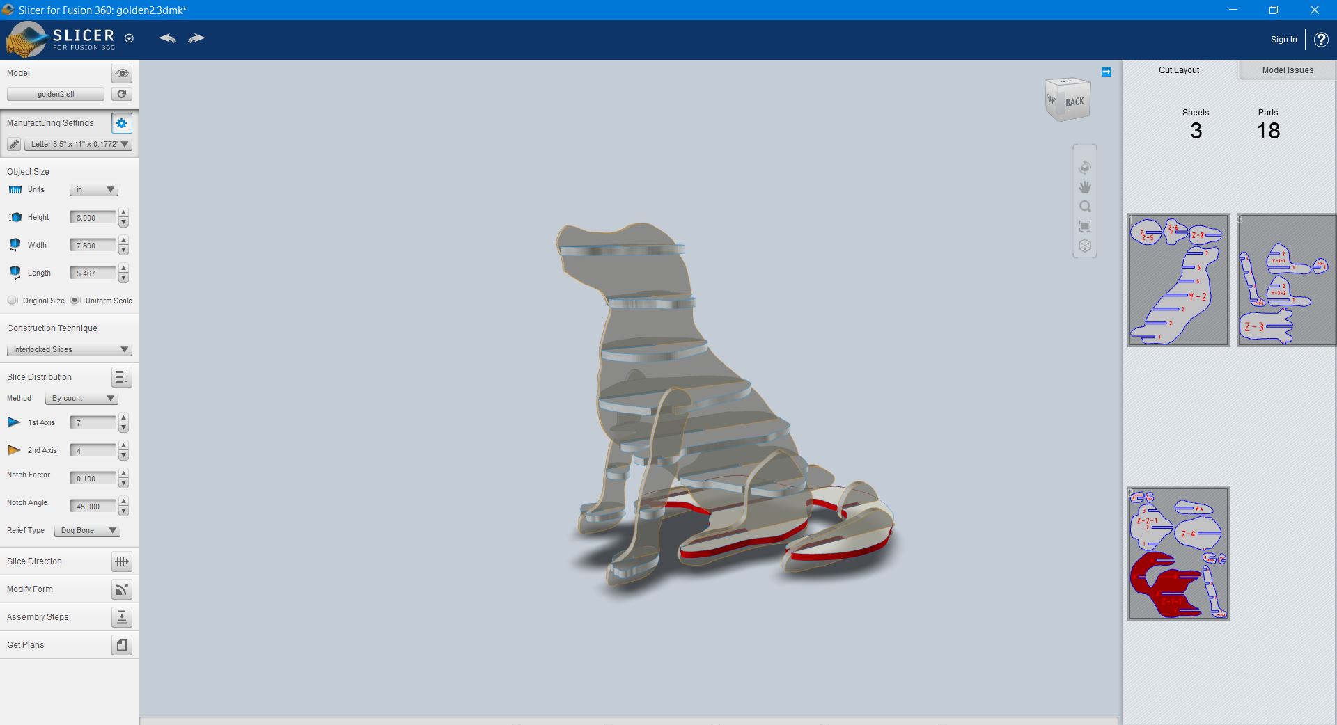
Now it’s time to get slicing. Slicer performs a number of slicing tasks. If you wanted to make slices of cardboard to create your model, it will do it.
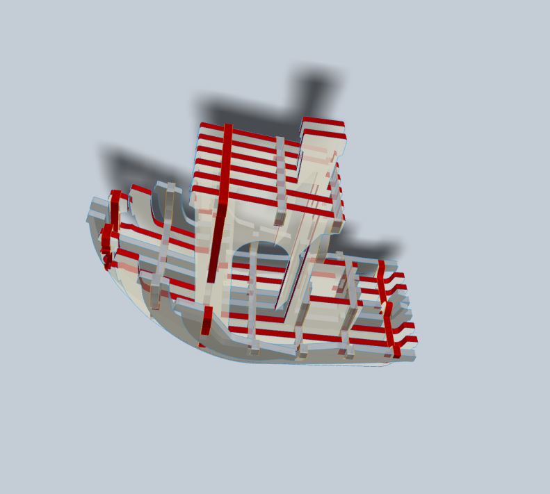
But I was interested in the “Interlocked Slices”
You can change the number of slices in the Z and X axes. You can change at what angle they cross in relation to one another. Of course, you can choose the thickness of the slices. It even allows for a “dogbone” style clearance at the interlocking joints for ease of manufacturing (Though I do wish it also had a chamfer option at the opening of the notches as well. Updated: Found it, it has it, it just calls it the “Notch Factor” because calling it a chamfer or bevel would make too much sense.)
You can even modifiy each individual slice, and move it around if you need too, by going to “modify form” and choosing a particular slice.
The software will also show you a layout of your design on the material size you specified, and show you how many sheets of material it will take.
It also shows you if there are any errors in your part. Some of the “errors” are more warnings than anything, but this is something to pay attention too as you design your part.
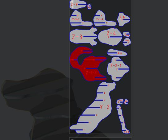
Once you’re satisfied, make sure to go to the “Get Plans” menu item, near the bottom left, and choose the file type (I’d suggest PDF, but frankly, I think all the options suck.) and then save to your computer.
One of the cooler things about this software is the “Assembly Steps” in which it will show you in what order to assemble the parts for the model.
Now we just have to make the thing.
Actually no, I still have to prepare this file. There are a number of edits I’m going to need to make.
I also want to test the design before committing to make the entire thing on a sheet of 8’ x 4’ plywood.
First of all is the size of the notches. Designing them to be the correct width, making them parametric, having them have the “dogbones” (very appropriate in this case I might add.), etc.
And I also want to make some design changes, a) to make it stronger b) to mix and match some parts from the first version with the 2nd version to make it more aesthetically pleasing.
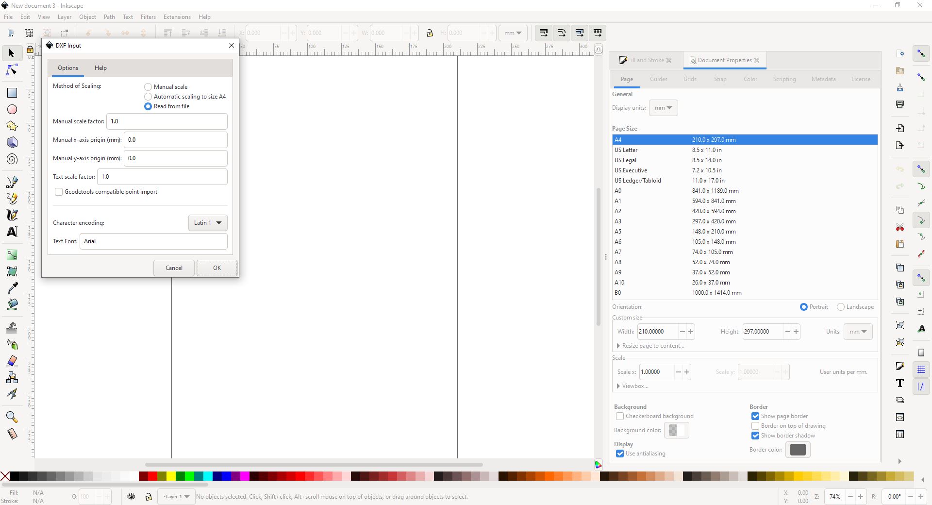
DXF is the Devil
DXF has been around for decades, and has long been a “standard” for line files in use in CAD, laser cutters, vinyl cutters, cnc routers and all sorts of other similiar cases.
But as a file standard, it’s garbage. There are multiple versions of the DXF file format, and they’re not very interchangeable. There’s also no easy way to see which version the file format is saved as (as far as I know.)
I’ve used multiple programs in order to create this project, and just about every time, I’d get one program refuse to open a DXF from another (Inkscape didn’t want to open up the DXF straight from Slicer.), or get an error (Deepnest didn’t want to open up a DXF saved fron Inkscape.) To be fair, Inkscape does seem to be the common denominator here, but regardless of the cause, stay away from DXF’s.
One solution was that I had access to Autocad, and as it’s literally where DXF comes from, I used that to help convert files into a more “standard” DXF format. But that meant using one more program just for simple file conversion (conversion of the same file format.)
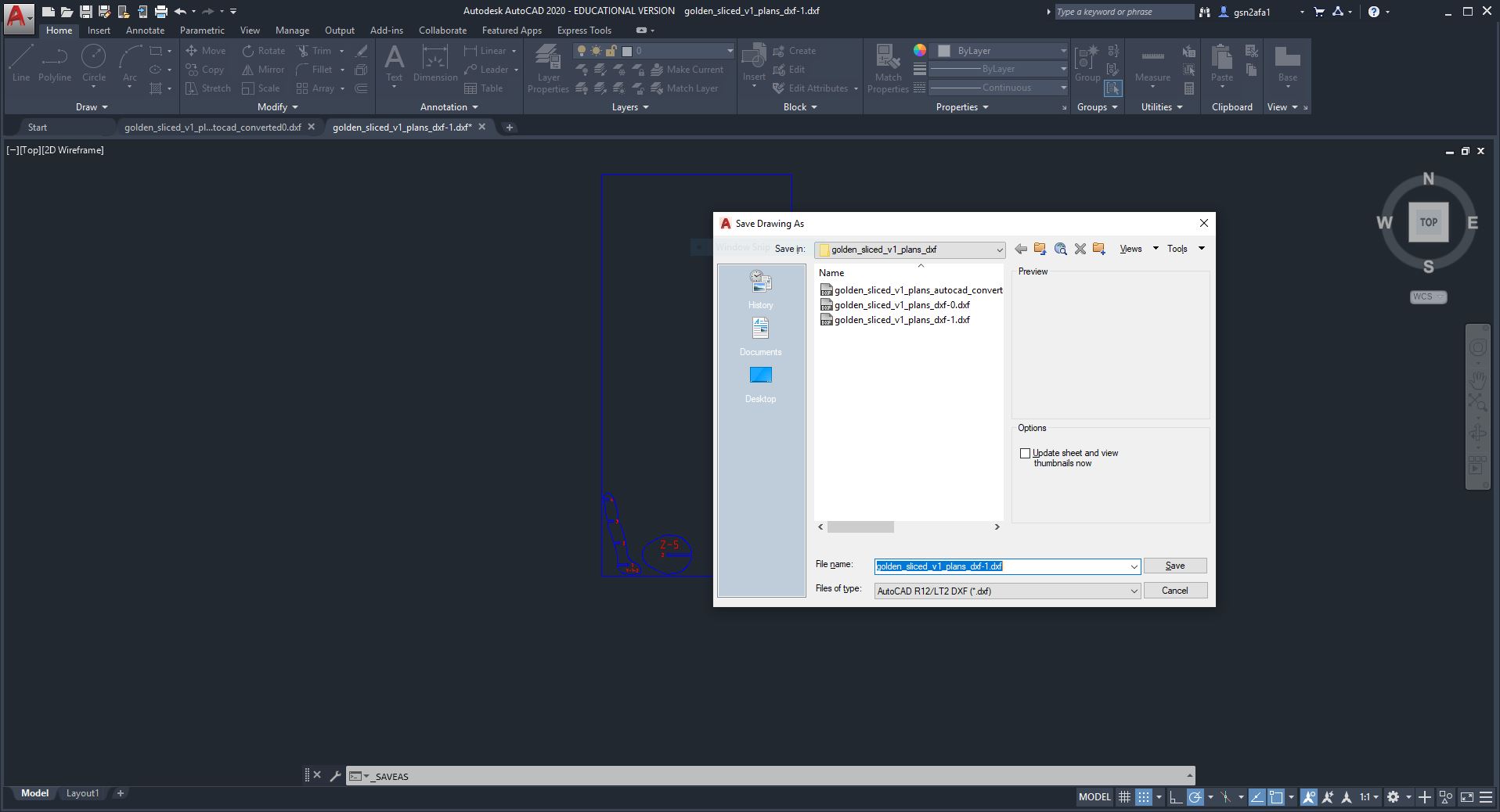
I’ve been saving my files in SVG’s, however, there are plenty of CAM programs (especially older, simpler ones) that may not take SVG.
Just keep all of this in mind when working with these formats, as at some point you may run into an issue with DXF.
Making a Test Model
I took the files, and after dealing with the whole “DXF is a pita” problem, I put them in Inkscape, shrank them 25% (which worked great, because these were designed for 1/2” thick plywood and I was testing these on 1/8” cardboard, shrinking them to a quarter size made the notches line up perfectly with the 1/8” cardboard I was using to test.)
I followed the directions on using the Laser cutter from Week 4 and cut the models.
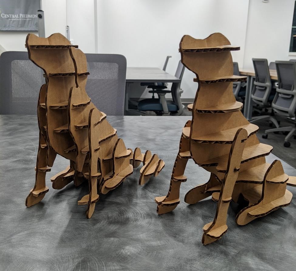
I made two different versions of the design. One was simpler and more “open,” the other looked more like a dog, with more details, but was much more difficult to put together.
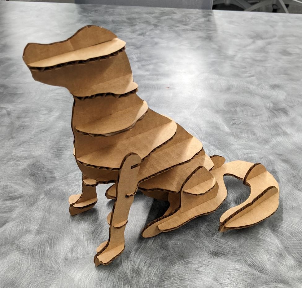
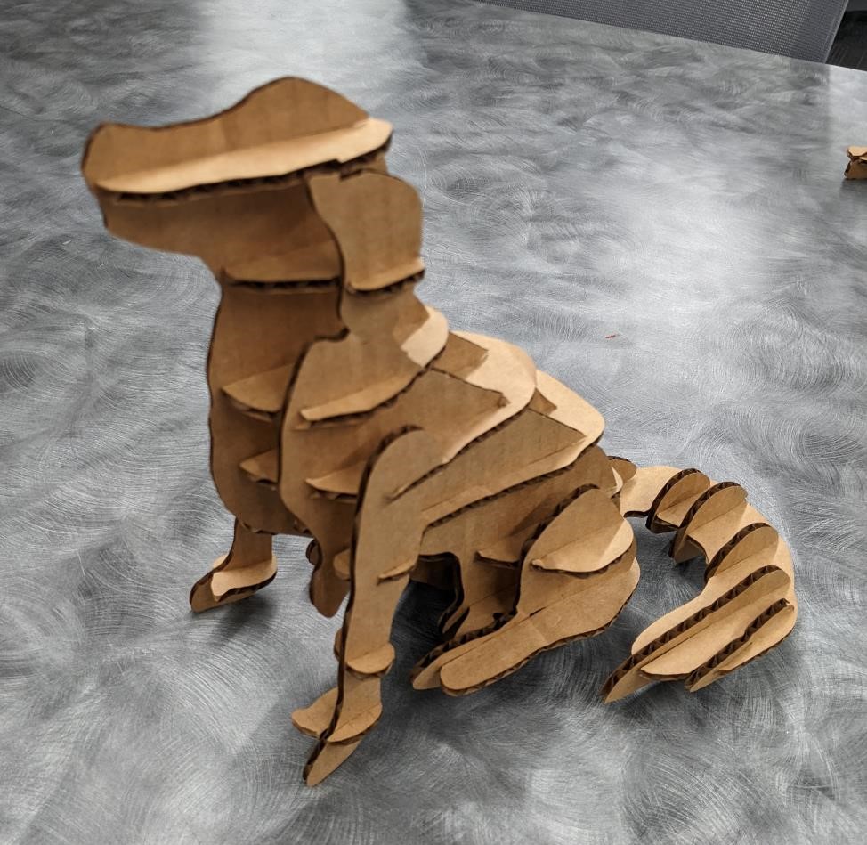
It took much more than twice as long to put it all together. It was overall a much more frustrating experience as well. (This did have a lot to do with the material though, the cardboard wanted to move, stick to itself, and was just a pain to work with.)
I’m glad I did this, as it made me definitely choose the simpler version. However, I’m going to take some details of the second, and add them to the first. (For istance, I really like the tail looks on the 2nd version, it looks very fluffy.)
Trying to Nest the parts for optimization
DeepNest
I didn’t really need to nest my parts, as everything fit on 8’ x 4’ piece of plywood fairly well. But in the sake of effiency, (the cheap machinist inside of me demands saving as much stock as possible) and curiosity I wanted to try some software that would do automatic nesting. I know that Fusion 360 now includes this feature on some of it’s higher end plugins, but someone in the class had mentioned “DeepNest” and so I though I’d give that a try.
So I downloaded and installed DeepNest and gave it a shot. But just reading the copy on the Deepnest website, it’s obvious this was desgined for lasers, not necessarily cnc routers, though it can be used that way.
First thing, it didn’t want to read one of the DXF files. So I tried an SVG. However the SVG had a box around everything, showing the size of plywood (48” x 96”). It did not see this box as it’s own seperate entity (or the “sheet” as deepnest uses in terminology.)
I edited the file, removed the box, and then re-inserted one via Deepnest. This actually caused Deepnest to see each indivdiual part. I set some options. I clicked “Nest” and …
and waiting…
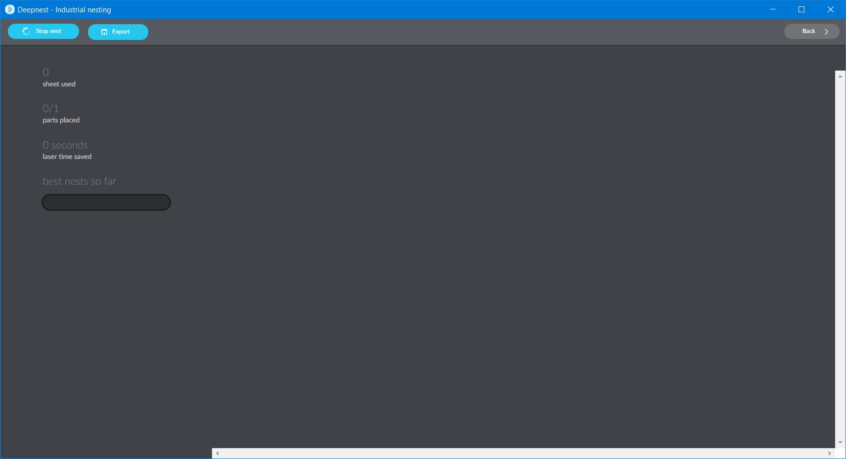
and waiting…
I’m doing this on an older, under-powered laptop, and I understand that Nesting is considered a hard problem for computers to solve efficiencly. But damn, this took about an hour to produce 1 result, which only had 14 of the 20 parts on the piece of plywood. Considering everything fit on the original 8’ x 4’ piece of plywood, this was going backwards.
Something is not working. I let it run for another hour or so. Not much improvement.
I tried again. It took another hour.
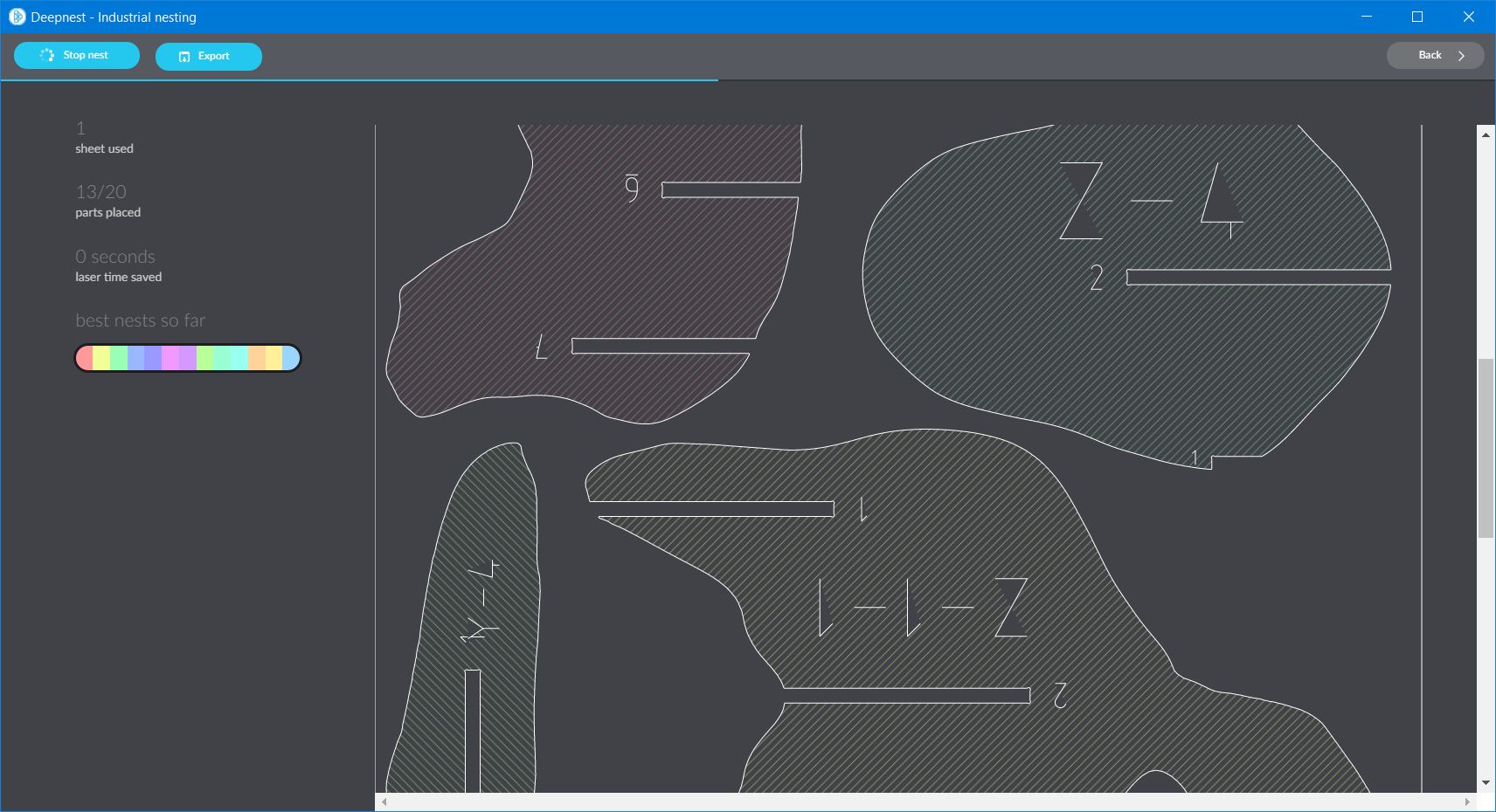
And there seems to be a scale or units issue causing this.
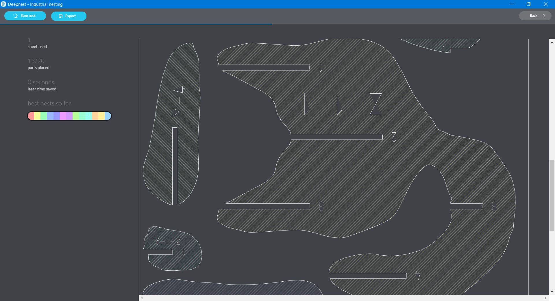

As you can see above, looking at the “fluffy butt” portion of the model, the deepnest version seems to take the entire width of the material, but the inkscape only takes up about half the width. I’ve checked the numbers on both, and both material sizes were set to the same 48” x 96” inches (inkscape was actually set smaller as I included a “border” around the part for hold downs.)
UPDATE: Found it, yep, there’s a setting in deepnest for units/inch. It defaults to 72. Inkscape defaults to 96. I have a feeling that’s it.
Needless to say, I said screw this and just massaged a few things by hand to make everything fit somewhat nicely.
Not impressive Deepnest.
Once I figured out the DPI issue, I ran Deepnest again. It’s results were barely more useful than the stock results directly from Slicer. I stuck with the results from Slicer. This was a waste of time.
Now we make the thing.
Or not. See Below.
First off, shout out to Adam Harris
Adam Harris spent 12 hours with Cori and myself working on this project. On a Saturday. During his Spring Break. I think it goes above and beyond.
Shout in to Cori, who may be able to run a 5 axis like a wizard, but can’t run a shopbot to save her life.
Shout out to Charlotte Latin
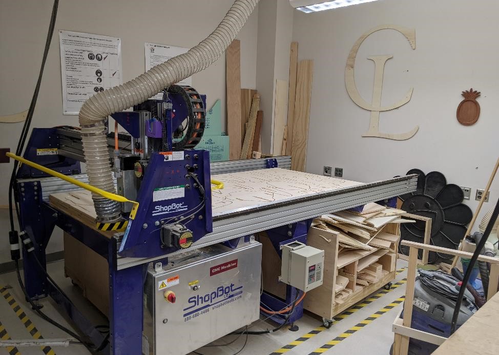
CPCC is currently lacking in a large scale, operational CNC router. Charlotte Latin’s Fablab, including David Taylor, Tom Dubick, and others (Barbara and Nidhie) were kind enough to host us on Saturday.
It was great to see another fablab, learn from them, see what they’re working on, and experience share their frustrations and their joys. (I’m very much looking forward to seeing Nidhie’s Dress Form)
They were very friendly and welcoming, and it was nice to talk with them.
Preparing to mill
We used a Computer Aided Manufacturing software (CAM) called Aspire to prepare our files for the shopbot cnc router.
Aspire is designed around woodworking and CNC routers, and is a very nice program.
While I tried to prepare my files as best I could, and I knew the general system we would be using (Shopbot with Aspire CAM software), I had never used either before, and therefore I wasn’t able to completely prepare my design for insta-machining. Part of the issue was the DXF problem, and then I had made an important mistake (wrong size of the tool.)
The issues I ran into included:
Line Segments
First, I needed to group each of the individual line segments for the entire project. While I had done this already in Inkscape, apparently it didn’t actually count and I was forced to re-group each item again in Aspire. (In Aspire, it was actually the “Join” command. And I’m going to try and look into this behavior so that I can be better prepared next time.)
FYI on simplificiation: If you “double tap” the “Shift + L” to simplify in Inkscape, it supposedly increases the amount of simplification that occurs. Also, you can change the amount it defaults to simplify (the length to join essentially) in Edit -> Preferences -> Behavior, and then increase this to adjust how much or little it will simplify your model (to an extent.)
More on Inkscape and simplification. https://inkscape.org/doc/tutorials/advanced/tutorial-advanced.html#:~:text=with%20the%20source.-,Simplification,creates%20more%20nodes%20than%20necessary.
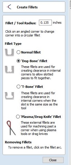
Wrong sized Dogbones.
The second issue I had was that the dogbones that were automatically produced in Slicer for each of the slots, was much smaller than it should have been. Looking back, I’m sure this is my fault, and that I had set this to be created using a 0.125” (1/8” or 3.17mm) bit, instead of the 0.250” (1/4” or 6.35mm) endmill that we ended up using. This was a dumb mistake, especially since David let me know we would be using a 1/4” upcutting sem (square end mill).
This however, was an easy, if time consuming fix. Aspire allows you to create dogbones. However, since I already had dogbones on each slot, (And it’s actually awesome that this worked. Props to Aspire’s programmers) I could use the fillet tool on my dogbones, which would create a nice radius of whatever dimension. I could click this again and it would remove the radius, creating square slots. Then I could use the dogbone tool and go back to actually place the dogbones, by setting the diameter to 0.250”. This worked amazingly well. There were only 3 or so parts that this did not work. In those cases, I had to use Corel Draw to manually draw in the dogbones.
Prepare spots for screws
Since my fixturing was literally screwing the plywood to the spoilboard, I needed to make sure that I placed the screws in positions where I would not actually hit them. The easiest thing in this case is to just take a spot drill (I just used a 1/4” endmill. It’s softwood.) and program in spots around your cutting paths. Then program these, to a very shallow depth, just making a mark on your board, and then you can place screws in these spots knowing that you should avoid the screws during your cutting passes.
Using Aspire CAM
After importing my file in Aspire, you need to set your stock size.
MAKE SURE TO SET THE Z ZERO FROM THE BED. (ask me how I found this out.)
I had to make a number of changes to my part, and as such I used the fillet tool to change too small dogbones into larger dogbones for corner clearance.
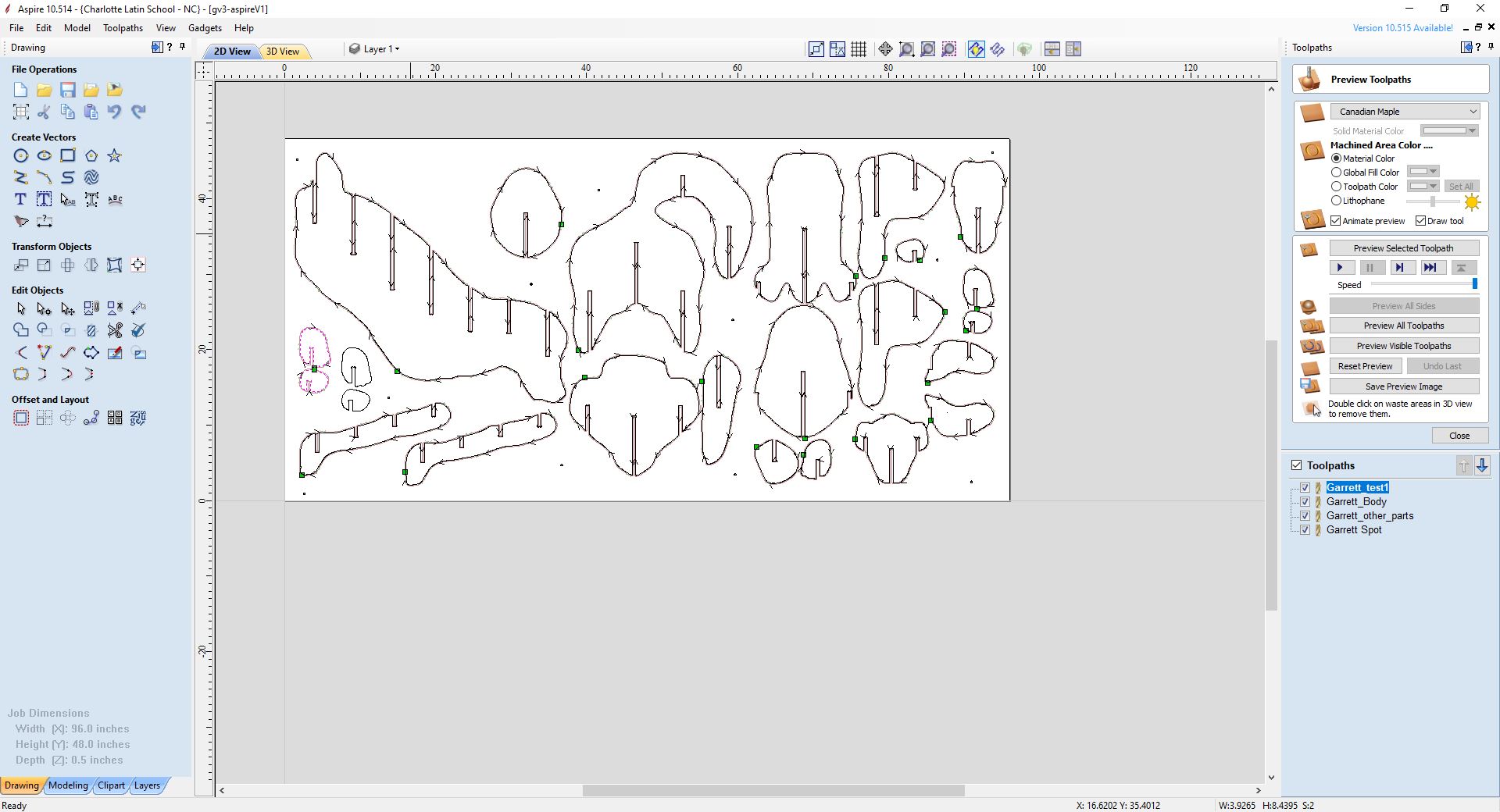
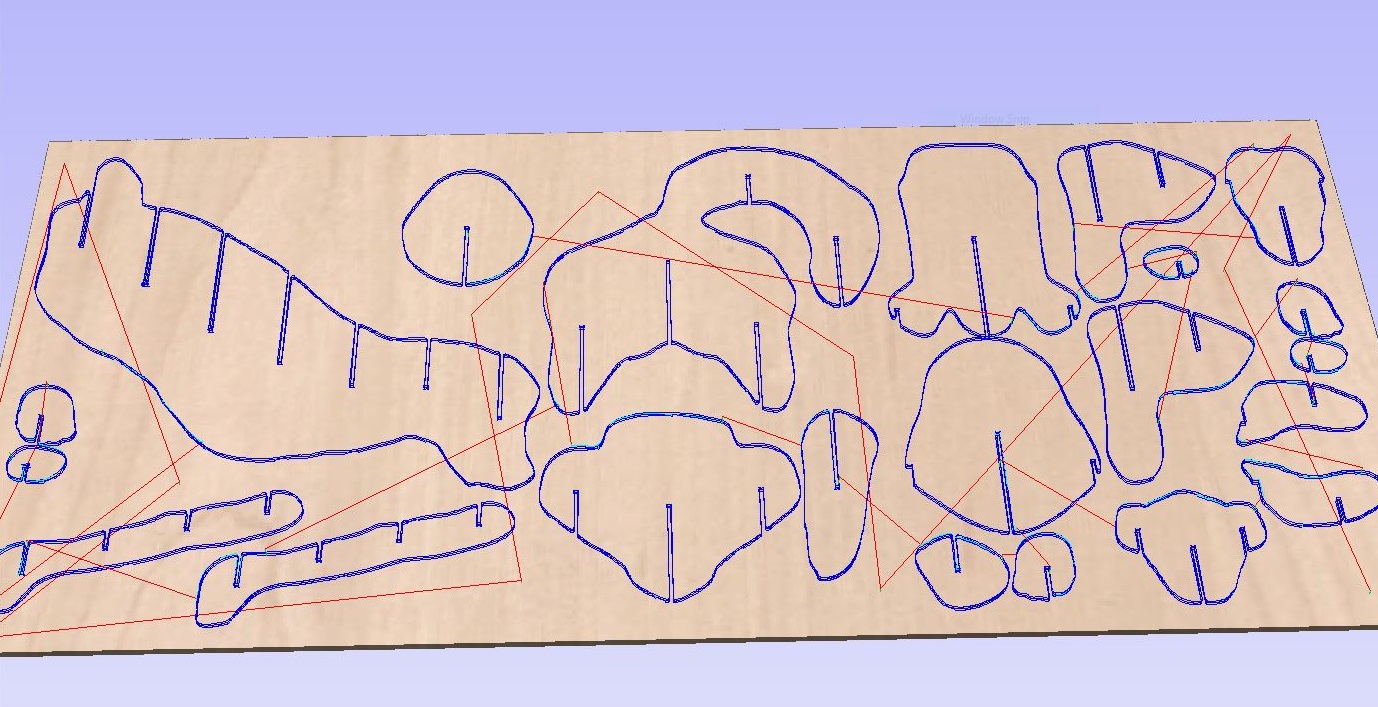
The below is an overall view of the Aspire window when you load, import your DXF/SVG/etc. vector file, and select your contours and prepare them to cut.
Note the toolpaths are named with the author (a lot of people are making a lot of parts at Charlotte Latin) some type of descriptive about what the toolpath is or does.
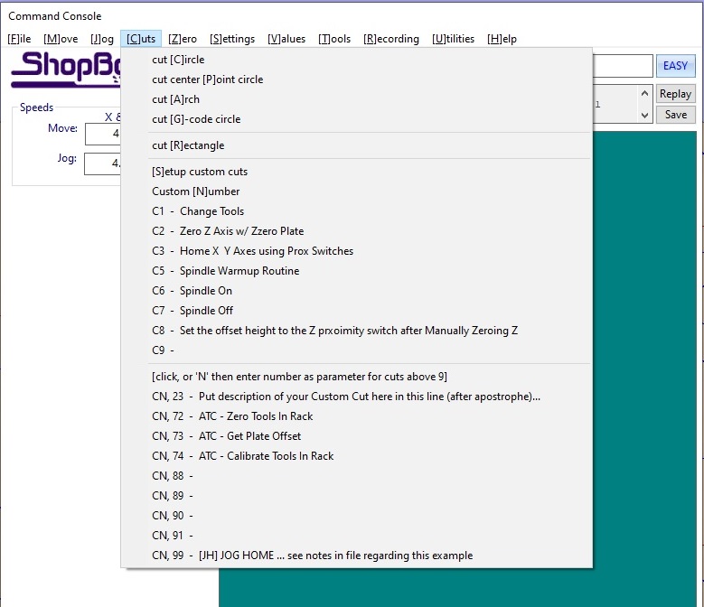
The below shows the toolpath menu for a 2d profile (contour) toolpath and the options.
First, choose the profiles of the parts/contours you wish to mill. Then we select the 2d Profile from the main toolpaths menu and it brings this up.
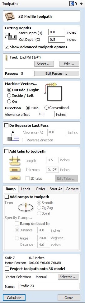
NOTE: The “Allowance Offsets” are where you can change the offsets of your toolpath, and make the size larger or smaller. THIS IS HOW TO SET OFFSETS, AS SHOPBOT DOESN”T HAVE ANY (APPARENTLY.)
We want to first set the Depth of Cut we’re going to take. In this case, it was 0.500” plywood, so I’m cutting 0.500.”
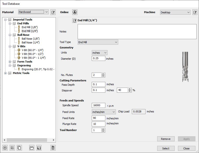
Then we select our tool.
The below shows the setup for the tooling. We were using a 1/4” upcutting 2 flute endmill. Running at 16,000 RPM, and 90 inches/minute
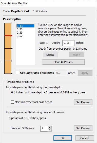
Next, let’s select the number of stepdowns.
The below shows the stepdowns, how many depth passes this will cut. You can set the relationship of this in the above Tool Selection screen (in the case of the 0.25” endmill, it defaulted to 0.100”.) I used 4 depth passes. NOTE: Any time you change the overall depth of cut, it is very likely to automatically change the number of depth passes. So keep an eye on this.
You’ll then want to select if you’re cutting outside the line, inside the line, or on the line. (usually you’ll probably be inside the line.)
This is where you can set small offsets, since the Shopbot does not have them on the controller.
You’ll also want to set your “tabs” if you’re cutting a part out of a piece of plywood and you don’t have any way of fixturing it. The tabs provide small pieces of wood connecting your part to the overall sheet of plywood. The tabs can be knocked out, and the part can be cleaned with sandpaper fairly quickly.
I used normal tabs and “edited” the tabs to place them where I wanted them. You can select custom and simply click where you want tabs.
We also used a Ramp cutting pattern, to make it easier for the tool to cut, rather than plunge straight into the material.
And finally, give the toolpath a name. Nothing’s worst than having 20 toolpaths, and not knowing what each one does. Name it something descriptive and unique.
The below shows us the toolpaths and simulation of what the cnc router should do after we’ve set all of our toolpaths. I’ll be cutting down to a depth of 0.520” (and my Z zero is from the top of the spoilboard.)
Once we’re satisfied, we can go into the Toolpaths menu, and then we can export the code.
Safety
At Charlotte Latin, their safety rules and procedures are very similiar to what we have at Central Piedmont.
Eye Protection must be worn.
Closed toe shoes are to be worn.
No loose jewelry is to be worn.
Hearing Protection is highly suggested.
At the end of the day, you’re responsible for the safety of yourself and others. Look out for one another, and don’t be afraid to speak up if someone isn’t being safe.
An Exercise in Frustration.
David gave us a tutorial on the Shopbot, as well as using Aspire CAM package to work with the router, and away we went.
And we had to ask questions, more questions, seemed like we broke the machine, etc. At this point I think they were saying “Machinists.. right…”
So, now comes the moaning and whining.
Let’s talk about Shopbots.
Let me forwarn you dear reader, the rest of this page is going to be about how horrendous Shopbot’s software is, and just how dumb their user interface is, and every other aspect of their system is just garbage.
Shopbot’s Software is garbage use other Software.
It’s really bad. Stupid bad. Everything about it is bad. I see no redeeming characteristics. I know two good replacements right off the top of my head that are free and would be so much better:
1) LinuxCNC
2) Any 3d printing board made in the past 8 years and Octoprint.
And I’m sure commercial software like Mach3 Cnc and Acorn CNC would work just fine.
It’s a CNC router. You send it Gcode. It moves, it cuts.
This is not rocket science. CNC is a solved problem.
Seriously, there is no reason that any professional software should be this buggy or this bad.
At least have the courtesy to do what Tormach does, use LinuxCNC with your own additions, features and user interface.
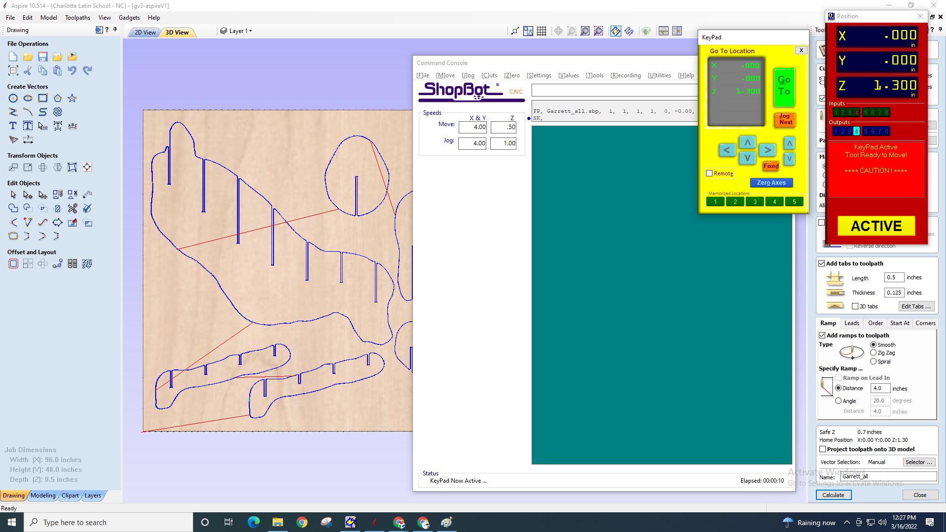
If you try to use the “Jog Handle” whatever the yellow pad is called, the software might crash. Yes, seriously, by opening a feature that is key to any CNC ever made. Moving the head around. On Shopbot, there’s a greater than even chance it might crash. Zero excuses for this.
Oh boy. And if you have the jog handle thing open on screen, you can’t do anything else, because…?
But you can actually click on the numbers in the panel and hand edit them. Which I would never have thought of, because it appears more like a display screen than an editable screen, but whatever.
So you have to use Shopbot’s proprietary weird code system (G-code is an ISO standard. Thanks Shopbot, the world needs yet another poorly thought out, poorly implemented way to talk to 3 axis cnc machines.) for the jogging. Which, if you’re trying to just move it “over there” is fine. But if you’re trying to move it a specific, but unknown exact coordinates, is not the way to do it.
Other problems with their software: lookahead
No lookahead. Modern CNC systems have lookahead, which looks to the next line of code, to see what the machine will be doing in the future. This is used in a number of ways. (and note, these explanations are not technically correct, but used for explanatory purposes).
First the machine is storing the moves in local memory, so that when the current move finishes, it can immediately go on to the next point. This may seem like common sense, but older machines, espically “consumer” or “pro-sumer” level may not have this capability, and there could be a lag especially from a system like a Windows PC, which does not run a real time operating system, and as such, the computer may be doing something else, like checking your email, rather than sending a steady stream of moves to the CNC machine. This may cause pauses and a “stuttering” effect of the machine tool. This may not sound like a big deal, but these cost time, and can negatively affect surface finish, tool life, and so on.
Second, it’s used for path planning. A CNC machine doesn’t just start and stop it’s X/Y/Z moves instantaneously, but rather these moves have to accelerate and decelerate. Good Path planning software does what the name implies, it plans out the movements of the machine tool. If it sees that coming up is a sharp, 90 degree turn, it can start decelerating in advance, to then prepare to make the turn. This provides a more accurate part, less wear and tear on the machine and tooling, etc.
They’re important. I’m not sure if Shopbot has these features, but from watching it, and watching it pause and stutter it’s way through some cuts, it doesn’t appear to have them (or at least not very good implementations of them.)
And…
And that warning klaxon. Holy crap, that is annoying. And talk about Alarm Fatigue. (Read that link.)
Shopbot, jump off of a cliff…
At one point, Cori and I needed to move the machine to screw down the stock, or for some reason. Cori had made two Y moves, one of 10 and one of 15. We had assumed they were incremental moves, our mistake. But when we commanded the machine to Y -25, to bring it back to the starting position, which starting at 0 at the front left corner would be 2 feet off of the machine, it tried to do this. Very unsuccesfully, hitting the hard stop (which is another thing all unto itself. It shouldn’t ever be hitting the hard stops unless something goes badly wrong.)
CNC machines are stupid, and do exactly what you tell them too. But most of them will at least have enough self-awareness that when given an obviously bad movement 2 feet past it’s limit switches, they’ll error out. Not Shopbot. (and by the way, part of this behavior is why Cori and I had assumed that this was in incremental mode, because it sure enough acted like it was.)
But if you do hit the limit switches, it freezes and freaks out. Because CNC software in 2022 can’t handle hitting limit switches and recovering gracefully apparently.
No offsets? Are you serious?
Shopbot relies on Aspire to do everything (and Aspire seems to be well built CAM software), but the fact that to make even the smallest changes requires going into Aspire to make a change, then back to the Shopbot controlling sytem. For 1 off’s and prototyping, not a big deal. But I can’t imagine trying to run production with this type of workflow.
This is why CNC machines have offsets. If your tool is just a tad small, if you need to drop the tool height just 0.010” more to cut all the way through the stock, you make a very quick change at the machine, and away you go. Not so with the Shopbot software. I guess they think that all of their machines, tools, and the wood plywood you buy is perfect and there’s no reason to make changes at the machine.
There are two types of tool offsets.
The first is about the height/length of the tool. This determines how far the tool will be moving up or down in the Z axis. This is setting your Z zero on many simple CNC routers.
But then you have cutter compensation, which is where even though tools may not be cutting as much material (or cutting too much material) as you may expect. This may be because of tool runout, or the type of material, the way the material is held, or a number of factors. In this case, you need to make adjustments, and that’s what cutter compensation (or tool diameter offsets) are for.
More on cutter compensation here: Autodesk’s intro to cutter compensation
I was asking about offsets, ie, a way to tell the machine the “real” diameter (or rather the cut diameter) of a machine, and no one knew how to do this, and I figured this is a good chance to learn how shopbot does it, and show them this excellent way to make quick, important changes on the machine.
Nope. Nope. Nope. That’d be too easy.
Okay, back to how to use this thing.
Stopping a Shopbot
A couple things to know before starting.
There are multiple ways to stop the machine. Know what these are and how to use them.
Know where the E-stop (Emergency Stop) buttons are located and how to use them properly.
There are two other ways to stop the machine, however they do not stop the machine immediately.
The Spacebar asks as a Pause button. Use this if you want to check something while the machine is cutting. The machine will finish it’s current move, then raise up.
The Reset/Stop button should stop the machine quicker, but I didn’t try it, so I wouldn’t count on it.
And then of course the E-stop which is the “Oh Crap” button. If you think you need to hit it, you probably do. Don’t be afraid to use it.
If all else fails, use a sledgehammer and bash the crap out of it. I won’t mind.
How to use the Shopbot
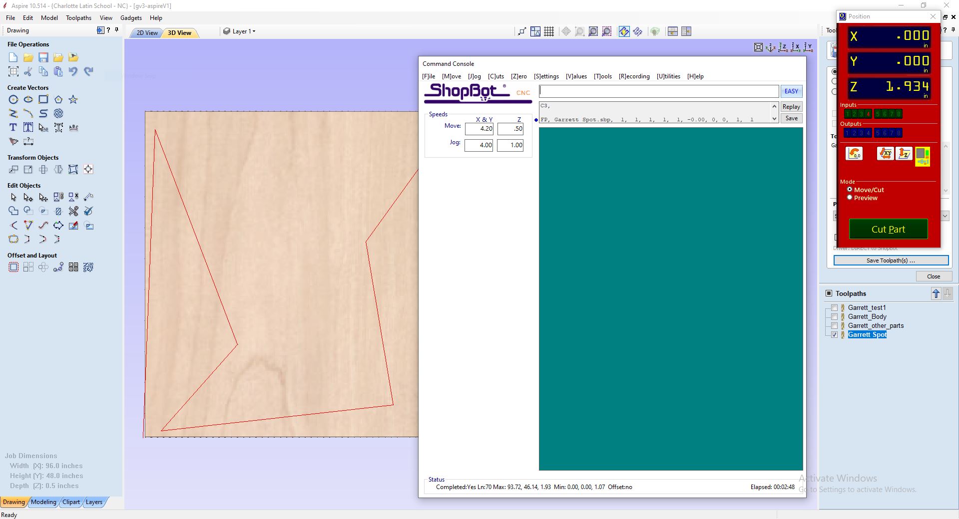
This will be the screen you will see when you start up the Shopbot software.
Remember:
- You can hit the spacebar to pass the program.
- The Blue btton on the pendant can
- The Emergency Stop if something really goes wrong.
Set Up:
- Having already posted and saved the code for the program you’re preparing to run…
- Open the Shopbot software
- Open the file you just saved (you need to do this before anything else for some reason)
- If you’re running the first part in air (as you should), set the offset to 1-3d offsets
- Then it’s time to move the head/spindle to where you can reach it, so that we can install the tool.
- type in JX, JY, 0,0
- The machine head should move to it’s origin/home position in the front left corner of the machine (when looking at it from the center of the room in the case of Charlotte Latin.)
- We need to check/install a tool. If the tool is already installed, you can skip to touching off the z height.
- Raise the dust collection skirt by loosening the black knob above the spindle motor and raise the dust collection system. re-tighten the knob.
- The bit/end mill is held in an ER 25 collet. These collets snap in and out of the locking ring.
- With the collet starting to thread on to the spindle, use the normal looking wrench (didn’t catch the size, looked to be about an 1 1/4” size wrench), hold the spindle with this wrench (the spindle has two cutouts for the wrench), and with your other hand, place the bit in the collet, and hand tighten the collet till you can’t move it.
- Then using the collet wrench (which is attached to the spindle engaged key), place this wrench from below on to the collet, and with both wrenches, push away from you to tighten the collet.
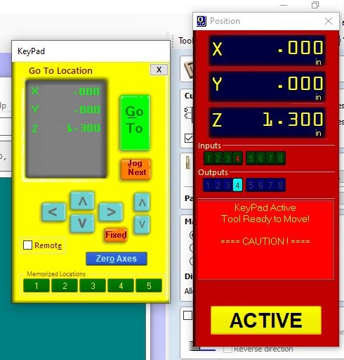
The below image is the Shopbot “Jog Keypad” Interface. Don’t use this too much, it will freeze up. If you try to open a program or do something with this open, it will freeze up the software. I wish I were joking.
Set your X, Y, and Z origins.
This is an important menu, and what you will be using during much of the running of the Shopbot.
- Now it’s time to set the Z height of the tool.
- Take the Zzero Pad, located above the spindle, on the head of the machine, and place it directly below the router bit, on the spoil board, not the part you will be cutting.
- Put the Zboard back up when you’re done.
- Then, use the Set Z zero tool height in the Shopbot software.
- When this is done, now we need to set our X, Y origins.
- You can either set this manually, or rely on the proximity and home position to set this. If you set this manually, you’ll need to put your stock on the machine first.
Place your stock.
- This is where you can place your stock on the machine and fix it depending on your needs.
- You do want to make sure that it’s close to where your origin is, or set the origin based on your stock.
- Once you place your stock and the tool in the X/Y position that you want, then go to the Shopbot software, and C2 (I think, doublecheck, but I don’t think I care that much) to set your X and Y home positions.
- Drop the dust curtain around the head of the tool to prepare for cutting.
- You may want to run the “Spot Drill” operation, to take small cuts for where the screws will go.
This image is showing the running the “Spot Drill Operation”. This puts tiny dimples where I will put screws, to make sure that they are in safe spaces, and will be unlikely to be struck by the tool bit when milling.
- Then screw the board down to the spoil board. Now you’re ready to go.
Run the Part.
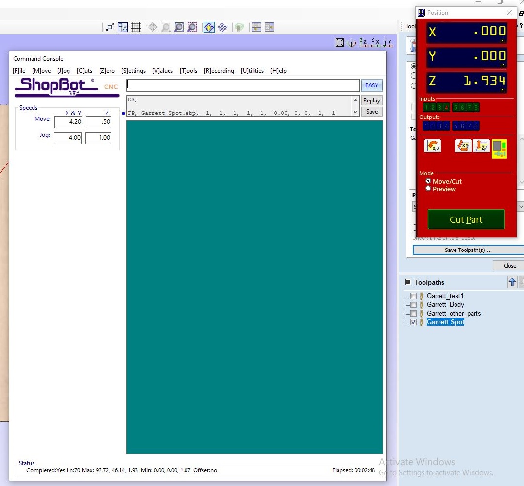
The below is the screen right before running the parts on the Shopbot.
- Start the Vacuum Dust Collection system (make sure the baffles/vents are in the correct position) (It’s the big green Start button)
- Send the machine to it’s Home position: JX, JY, 0,0 BECAUSE IT DOESN”T DO THIS AUTOMATICALLY. BECAUSE WHY WOULD IT?!
- Start the program (it will ask you to hit Okay. DON”T DO THIS WITHOUT STARTING THE SPINDLE.)
- Start the spindle by pressing the Green button on the pendant.
- Hit okay or press enter.
- You can hit the spacebar to pass the program.
- The Blue btton on the pendant can
- The Emergency Stop if something really goes wrong.
Then let it go…
But keep an eye on it. You want to make sure everything looks okay and that nothing is causing any issues, everything seems to be working.
Use yor ears, this will help determine if you notice anything that sounds off. If it sounds off, something is probably going on.
It’s Cori’s Fault
After getting some fairly nice 1/2” plywood, we were ready to finally start cutting.
This is when the trouble began.
I’m not quite sure how, but I’m pretty sure it’s Cori’s fault.
At first, the shopbot software would keep freezing. Just trying to jog the machine around caused it to freeze. Trying to do anything would cause it to freeze.
So we restarted the entire computer and this seemed to fix it.
But we were told, “don’t use the yellow hand jog thing, it doesn’t like that.”
Oh joy, a CNC machine that can’t handle manual jogging.
(And I don’t really think it was Cori’s fault.)
Clean your collets
After we got the machine to actually run the program, we had some serious inconsistentcies in terms of depth of cuts. I assumed that it had a lot to do with the shopbot hardware, because it didn’t appear that the tool was being pushed up into the collet untill…
We started just going down to a cut depth of 0.750” and this sort of solved the issue. There were some weird things gong on.
We finally felt like we got this sorted out and then as Cori was cutting her part, the tool was being pulled out of the collet.
We checked the collet and it was full of tar, dirt, gunk and dust. We cleaned the collet and gave it a thin coating of machine oil.
The inside of the spindle (where the collet sits against) was actually worse, and seemingly had a thin film of gunk on the entire surface.
The dirt and gunk in the collet (and especially in the spindle!) make it so that there is “give” when trying to compress the collet closed (which is what holds the tool), and this flex allows the tool to move up and down in the collet. These surfaces should be clean and smooth. It doesn’t just affect the holding power of the collet, but it’s possible it can affect tool runout as well.
We cleaned this out, re-set the Z zero, and started cutting again, and it cut beautifully.
Finally....
And at about 9:00PM, after starting at 9:00AM, Cori had her parts cut out.
I didn’t feel like staying, and I sure didn’t want to force Adam to stay for another two hours, so we cleaned up the shop, and called it a night.
We didn’t have a chance to work on the group project.
I didn’t have a chance to cut my project. Maybe I’ll get a chance again in the future, but for now, I’m just going to move on to the next project.
The real lesson to learn
CNC is relatively new, it’s popular, it’s been democratizied. It’s sexy.
But it’s not always the best tool for the job.
Given a printer, some elmer’s glue sticks, a table saw, a bandsaw, a drill press, and other miscellaneous wood tools, I could have completed this project in 12 hours. I think this becomes even truer when you calculate in the sanding time and cleanup costs associated with wood working. You can’t just take it off the router and slap it together.
I wouldn’t have had to re-design my parts, or fight with joining all the line segments. Things that cost me at least 2 hours.
I wouldn’t have had to learn a new piece of CAM software, or a horribly buggy CNC program, to fight with a machine (that is now astounding to me that it’s so popular.)
I would have printed out the templates, glued them to the correct sized pieces of wood, and then used a belt saw to trim them to their final form and dimensions. (and drilled out corners as necessary for the slots.)
I have seen too many students run for a CNC Mill or a CNC lathe when it would take half the time to just do it on a manual lathe or manual vertical milling machine.
I understand that these projects are about learning new techniques and technologies. But sometimes I fear we miss the forest for the trees. Is the lesson about simply the tools, or how to teach people to make things? Because if the later, you don’t have to have fancy CNC tools in order to think creatively and to make unique projects. Instead it’s about using the tools you have, in order to get them to do what you need, in order to make the things you want to make.
Wednesday Morning....
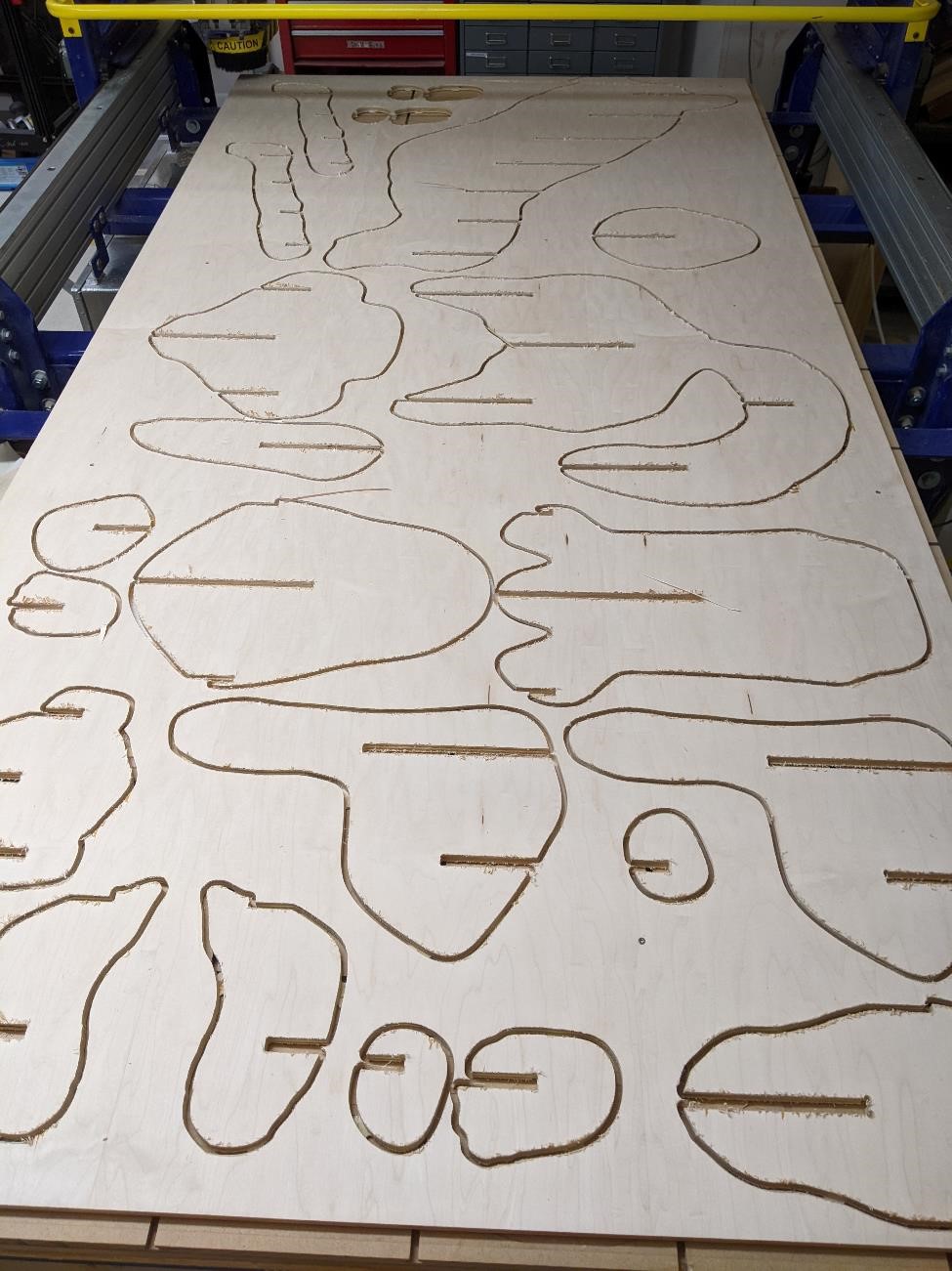
I got to get into Charlotte Latin’s FabLab again, thanks to David Taylor, and had a chance to actually cut my parts.
Again, this was using 1/2” veneer plywood, that mic’ed out within about +/- 0.500” (very tight tolerances.)
There were a number of issues cutting these out, not least of all was user error.
However, there was one strange error that I never quite got my head around, but there seemed to be an issue near the middle of the board where it did not want to cut the part out. I ended up going down and cutting an extra 0.050” deeper to get these parts to fully be seperated from the main plywood.
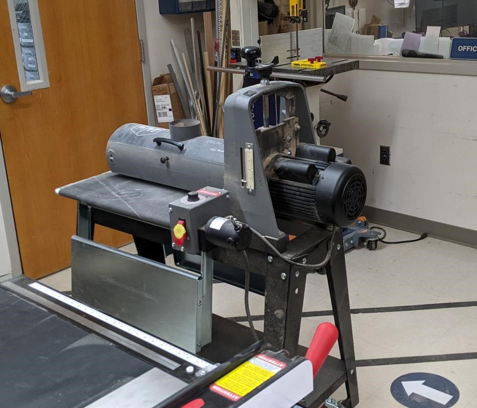
After they were all cut out, David Taylor showed me how to use the Drum sander (though he did all the work.) and helped me give a rough sanding to these parts. Be aware, you have to watch out for which way the grain is going, and for any serious warping of the plywood, or you may take off more than you expect.
David also showed me how to use the Reciprocating sanders, and between the two of us, we had these parts rough sanded in very short order.
And we did a decent job of cleaning up the shop (man, wood dust gets everywhere.) and we were done at about 2:30pm, after being there since about 9:30am. It never takes less time than you expect.
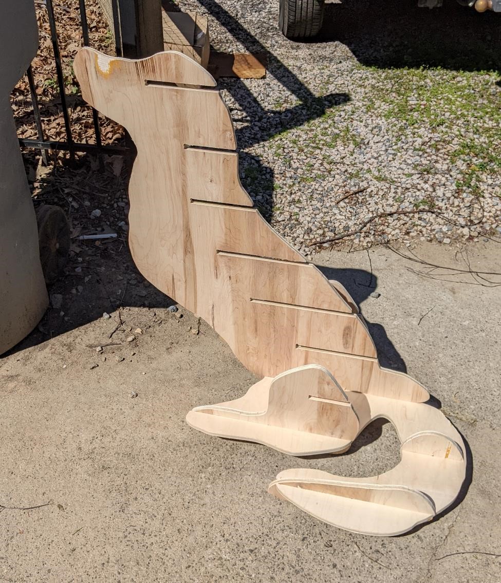
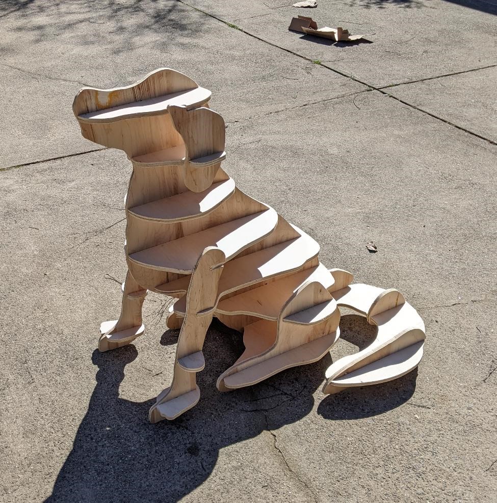
Sunday Afternoon…
I finally had a chance to put all the pieces together.

Thanks again for all of your help David.
Files
Here are the files for the simple version I’m building.
Group Project
You can find our group project here for now: Unit 8 Group Project
For the group project, we were not able to use the Shopbot, but rather used a Haas VF1 milling machine located in the Computer Integrated Machining shop.
I’m going to be honest. I learned nothing. I use this machine all the time, I know it very well. I know what I can expect from it, the tool holders and the tooling. I make programs for this machine constantly, and I teach students how to use this machine. I also teach students how to measure their parts.
If you want, I can write some BS about how I learned something, but it’d be a lie.
I picked out the crazy tool holder with two different adapters and a bad drill knowing that the runout would be ridiculous, and I knew that the runout of a ground edge finder in a fairly new collet and tool holder would be negligble.
I knew it was very likely that I would have have chatter on the part because the parallel I used had a giant nick in it that I didn’t clean up. I thought it highly likely that I would not get a perfect part, but rather I would have to tweak my offsets, especially as it came to the bore and the slot, especially for the bore considering the tool path I programmed for it.
Now, all that said, I bet I could have learned a whole lot more if I were able to do some of this on the Shopbot (and I did learn quite a bit about running a Shopbot and Aspire), but that’s just how it goes.
Not everything has to be a learning experience.
This was supposed to be the easy week.

“Hey whatcha doing? Let me get in the photo!”
I guess I’ll have to make one of the cat too.