17. Final Project Questions
May 18, 2022
This week is all about answering questions for my final project. I’m going to do my best to answer the following questions about the digitizing arm project I’m working on.
Please see the final project page and the work logs for more information.
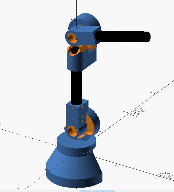
This was one of the early designs that I started with:
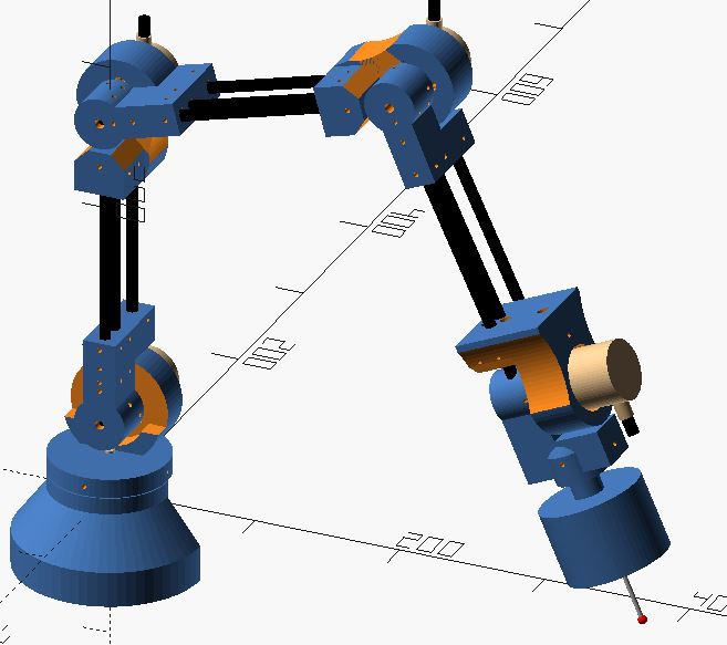
What does it do?
This is a digitizing arm that is designed to act as a coordinate measuring machine to help with taking measurements for quality assurance and reverse engineering. It will gather a collection of point clouds from the object being measured, and store and transmit these points to a computer running specialized software for further analysis.
Who’s done what beforehand?
Digitizing arms have been created before, even as FabAcademy or FabLab projects.
The below is a list of different projects and DIY prior art.
https://fablab.ruc.dk/diy-digitizer/
http://blog.dzl.dk/2018/08/21/3d-digitizer/
- I believe this is just an update on the fab lab project. Which includes a turn table.
- Excellent resource on how he found polar coordinates.
- Github for project: https://github.com/dzlonline/3D_digitizer2
https://www.thingiverse.com/thing:2882172
- I like the way that he added the weight, as well as the large ball bearing around the top of the base. I had previously thought of the bearing, but the weight is a good idea.
https://forum.makerforums.info/t/ccm-digitizing-arm-5-axis-faro-arm/78981
-
Github for project: https://github.com/BL-Shopwork/CCM-Arm
-
Found this late, but found it: A fablab digitizing arm project http://fab.cba.mit.edu/classes/863.17/Architecture/people/djmm/0.html
(And his DIY capacitive sensor, which apparently didn’t work: http://fab.cba.mit.edu/classes/863.17/Architecture/people/djmm/10.html)
-
Ricardo Marques is also building a CMM this year: https://fabacademy.org/2022/labs/fct/students/ricardo-marques/projects/FinalProject/Week10/
-
“Arm Style” CNC Mill http://fab.cba.mit.edu/classes/863.12/people/will/final/index.html
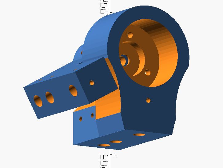
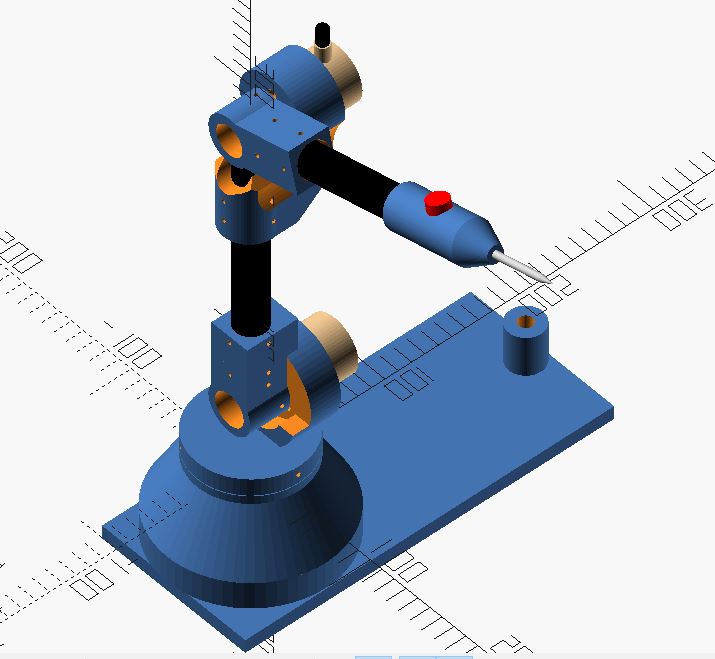
What did you design?
I designed the structure, as well as the electronic boards.
This includes the base of the arm, where the rotary encoders will be held. The connections for each arm as well as the encoder holder for each arm, as well as the probe tip.
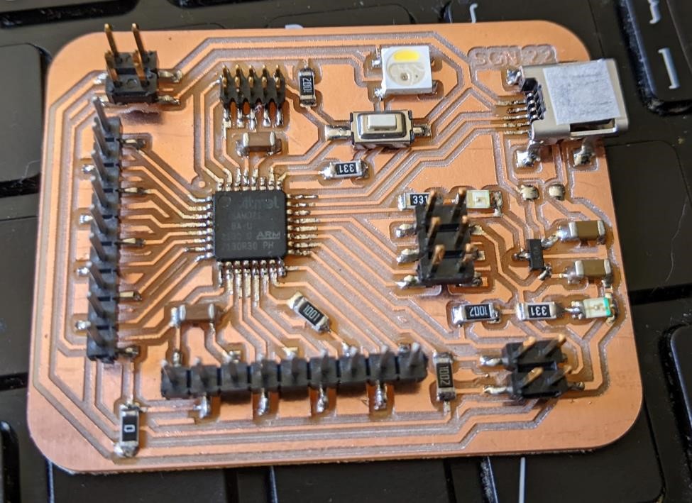
I designed and built the SAMD21 board that will be collecting data from the rotary encoders and be forwarding it to a computer for more complete analysis.
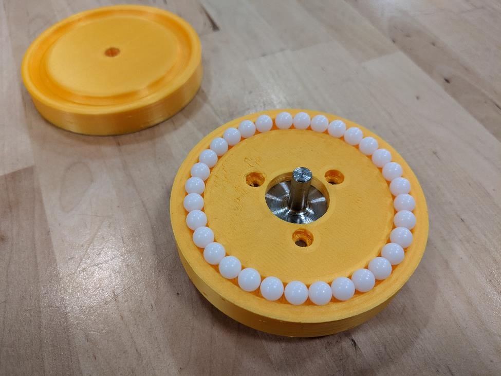
I designed the phyical structure. I also designed a ball bearing that would help hold everything together, and make the system (hopefully) run smoother.
I’ve also worked on software using Processing, that will collect data over serial and then convert it into a point cloud format that can then be used for creating a 3d model.
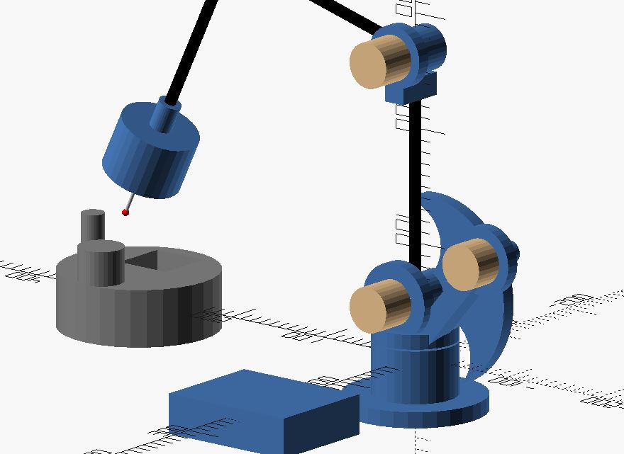
The below are images of some of the different design iterations of the project.
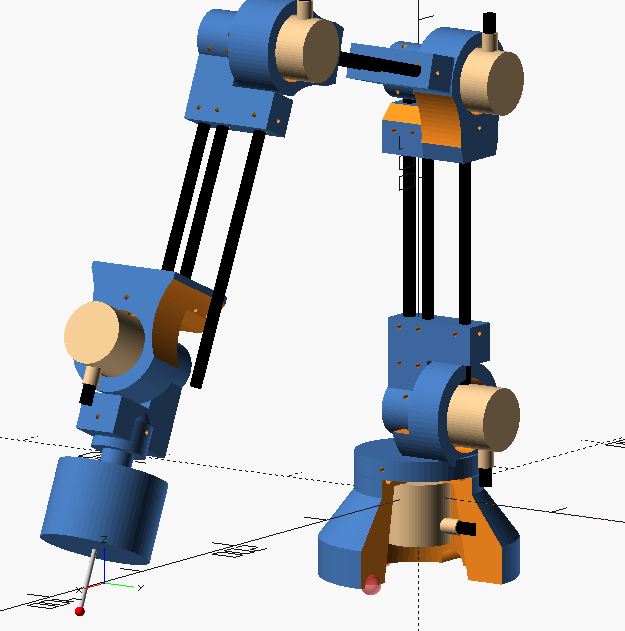
And the First Prototype
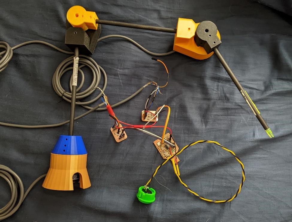
What materials and components were used?
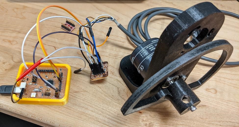
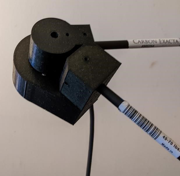
Here’s the first rotary encoder test that was successful:
I used a variety of different materials and processes to build the project.
Here’s an earlier test of some 3d printed parts with a carbon fiber rod.
Here’s a list:
For the Mechanicals:
| Part | Description | Quantity | Cost Each | Total Cost |
|---|---|---|---|---|
| Carbon Fiber Tube | 1 meter, 22mm diameter | 1 | $30 | $30 |
| Rotary Encoders | Omron E6B2-CWz6C | 5 | $25 | $125 |
| POM Ball Bearings | 1/4” pom balls | 100 | NA | $12 |
| M4 bolts | 12mm long | 30 | NA | $5 |
| M3 bolts | 8mm long | 30 | NA | $5 |
| PLA filament | physical elements | around 250 grams | $20/kilo | $5 approximately |
| 2” x” 2” x 3” aluminum | for foot switch | $10.00 | $10.00 |
For electronics:
I’ll be using a SAMD21 board I designed, as well as a logic level converter board.
| Part | Description | Quantity | Cost Each | Total Cost |
|---|---|---|---|---|
| SAMD21E18A | microprocessor | 1 | $4.30 | $4.30 |
| 10uF Cap | 1206 | 2 | $0.04 | $0.08 |
| 1uF Cap | 1206 | 2 | $0.04 | $0.08 |
| Green LED | 1206 | 2 | $0.05 | $0.10 |
| WS2812B | Neopixel | 1 | $0.50 | $0.50 |
| 330R resistor | 1206 | 3 | $0.02 | $0.06 |
| 10k resistor | 1206 | 3 | $0.02 | $0.06 |
| 1k resistor | 1206 | 1 | $0.02 | $0.02 |
| 0R resistor | 1206 | 1 | $0.02 | $0.02 |
| LM3480-3.3 | SOT-23 | 1 | $0.42 | $0.42 |
| USB B Mini Connector | SMD | 1 | $1.02 | $1.02 |
| Pin Headers | Various | 42 | $0.01 | $0.42 |
| Button Switch | PTS636 smd | 2 | $0.16 | $0.32 |
| Stomp switch | momentary | 1 | $2.50 | $2.50 |
| 1/4” jack | 1 | $1.20 | $1.20 |
please see the page where I discuss the SAMD21 Board.
Please see the page where I discuss logic level converter board.
Here’s the electronics board that I was using to develop the project:
Where did they come from?
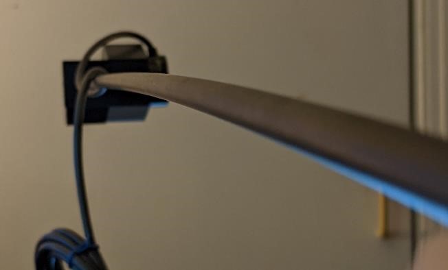
This was testing the stiffness of a 7.65mm carbon fiber rod.
Many of the electronic parts came from our FabLab inventory. Some electronicsparts came from ebay.
The carbon fiber tube and rotary encoders came via ebay ( and one of the reasons I know the “Omron” encoders are counterfeit.)
How much will they cost?
See above for mechanical component costs.
See above for electronics component costs.
Notes on costs: I thought that larger diameter carbon fiber tubing would be very expensive, but it was relatively inexpensive compared to what I was expecting.
The rotary encoders were counterfeits, if they were real encoders, they would have been over $300 a piece, which using 3, 4, or 5 would have quickly made this project cost prohibitive.
However, the electronics parts are quite inexpensive.
Real Costs
One of the more infamous statements is “Open Source is free as long as your time has no value.”
I think we need to take into account the labor, as well as infrastructure when taking in the costs of the project. While this is a learning environment, and this is very obvious to everyone involved in FabAcademy, I feel it’s important to make note of all the time it took to get to the point to be able to develop this project.
what parts and systems will be made?
The body, arms, connectors and electronic components will be manufactured.
I am using 3d printing in order to build the connecting parts.
I’ll be using a manual lathe in order to turn the main body out of aluminum.
I’ll also be laser cutting to make a larger base to hold everything together.
I’ll possibly be adding cast feet if I have time.
what processes will be used?
I’m using CAD/CAM, 3d printing, and electronics production.
I have the rotary encoders providing inputs. I’m using neopixels for localized outputs, as well as sending data over serial data to a computer to be input into Processing.
I’ve designed and manufactured a pcb using a SAMD21 board (as long as multiple test boards throughout the semester.)
And I’ve used a number of many processes learned throughout FabAcademy on this final project.
what tasks need to be completed?
Programming is the major task that needs to be completed. Both of getting the data from the encoders into a board capable of using interrupts to read the data, outputting this data to the computer, and then having a computer process the data.
I need to mill out the base from aluminum.
I need to finish 3d printing the base and some of the connectors.
There’s still a lot that needs to be finished, but I’m slowly making progress.
what other questions need to be answered?
How will I align everything precisely?
How well will the data be collected through interrupts and forwarded to a computer over USB serial?
How will I model this arm in a application?
How will I collect and store the data?
How stiff will the PLA be?
What’s going to take way too long to figure out?
I don’t know what I don’t know.
what is the schedule?
I’ll be spending the next week working on getting the encoder working.
The following week, week of May 25ish, I’ll be working on electronics and programming.
After that, I’ll create a rough prototype of the mechanical section that is a limited set up (just a coule of rotary encoders, not the entire system) for testing purposes.
Then the following week, early June, I’ll focus more on application programming After the testing and data input, I’ll move on to get the programming done, likley using Processing.
3 days before the presentation will be packaging and assembly.
If I have any time, this is when I would like to try some experimental aspects I’ve been hoping to include, but I haven’t had any time to work on.
how will it be evaluated?
If I can even mildly get data out, and the points are even mildly coordinates that are in the current galaxy, then it works.
But I’ll probably take a body of exact and known dimensions and test the digitizing arm with it, and this will give me an idea of the accuracy and repeatability of the system.