Work log - Week 4 - February 16, 2022¶
This is just a way to keep a record of what I’m doing during FabAcademy Spring 2022.
2/16 - Wednesday¶
Class Links -¶
https://class.textile-academy.org/2019/students/jessica.stanley/projects/02make/
Here you can see our synth collection: <https://timara.reclaim.hosting/gear/s/studios/item-set/113<> or take a virtual tour of our Technology in Music and Related Arts studios at Oberlin: https://my.matterport.com/models/jU1upG7Fr9D?cta_origin=all_spaces_page§ion=media
https://fabacademy.org/2022/labs/waag/students/bas-pijls/blog/week3/
cadquery
https://woodworkerb.com/home/pcb-isolation-routing/tool-width-calculator/
Soldering Bootcamp: https://vimeo.com/669526883
Reviews and Classes: https://vimeo.com/showcase/9247910
Recitations: https://vimeo.com/showcase/9247922
- Finished documenting week 3 group project on laser cutters
- Actually used transfer paper to move my vinyl cutouts in to real life stickers. Gold Stars for my students, here we come.
2/17 - Thursday¶
- Spent too much time working with the Roland SRM 20 mill trying to mill out a pcb for this weeks project on creating a programmer board.
-
The board file was based off of this design: https://fabacademy.org/2020/labs/ulb/students/quentin-bolsee/projects/samd11c_uart-updi/
-
The above board was modified by Dr. Adam Harris and information about it can be found:https://sheekgeek.org/2022/adamsheekgeek/samd11c-multi-use-board
-
I followed the instructions also created by Dr. Adam Harris from his webpage here: https://sheekgeek.org/2022/adamsheekgeek/how-to-export-to-a-cnc-from-kicad-and-fab-mods
-
And this very good video on the process of going from Mod to the SRM 20 mill. https://www.youtube.com/watch?v=znp10a4vALY
-
I ran into a multitude of small, but important issues
- I accidently used an older version of the above board design. It only differed slightly, but the PNG file for the traces was offset from the cutout layout by about 1 to 2 mm, and was missing one resistor. Was able to fix.
- the Mod software used to CAM out this board had issues downloading the file. Refreshing the page finally worked. (I am going to try and using the Mod Community Edition next time. http://modsproject.org/)
- Had near mental breakdown, as just putting code in and pushing the big green button, while not being able to see any of the gcode/control code is antithetical to everything I’ve ever been taught about machining. Because also, I’m going to rely on some half-assed CAM system that’s completely online based and then just send it to a few thousand dollar machine and just hope it all works out. Just no.
- The 1/64” endmill was starting to get slightly dull. Still acceptable results, but fine tearing was noted.
- Mod does not handle REST machining. Wasted some copper finding this out.
- Mods software uses non-traditional machining jargon. Will start referring to GIF’s as “jiffs” and memes as “me-me’s” in retaliation.
- When doing cutout of pcb, Mods and Roland SRM 20 didn’t want to actually cut through the entire depth. Had to drop offsets manually by about 0.6mm.
- Finally realized that the above issue is because you can actually set the Z origin position too low, and when the machine feels like it’s going to move below this point, instead of erroring out like a normal machine, it simply decided to go to it’s Z home position in the air and continue milling in the air. Nick Nalley told me this, thanks Nick.
2/18 - Friday¶
literally spent 7 hours working in the lab on the programming boards. I had previously made one board. However, being an old version with a cut trace and hack, I decided to create another, new version. This is how the day went:
- Milled the new board.
- Stuffed and soldered the new board.
- Tried to program the new board.  Failed
- Spent time looking over new board for cold solder joints and shorts
- reflowed the entire board.
- Still no luck with programming.
- bugged the ever loving crap out of Adam Harris.
- googled for potential solutions
- Came across <https://www.eevblog.com/forum/microcontrollers/does-anyone-have-experience-debugging-cmsis-dap-firmware-itself/50/>
- This tells me the programmer can't find the board. Well no shit.
- Milled another board.
- Stuffed and soldered the new board.
- Tried to program the new board.  Failed
- Spent time looking over new board for cold solder joints and shorts
- reflowed the entire board.
- Still no luck with programming.
- bugged the ever loving crap out of Adam Harris.
- Took a break and ordered PCB's from JCLPCB.
- bugged the ever loving crap out of Adam Harris.
- Took a break and milled a test piece.
- bugged the ever loving crap out of Adam Harris.
- Took a break and put the test piece on the optical comparator.
- Tried to program any of the boards.  Failed
- Spent time looking over new board for cold solder joints and shorts
- reflowed any suspicious connections on the boards.
- Still no luck with programming.
- Said "Fuck this shit, I'm going home."
And that children, is why I don’t do SMD soldering by hand.
2/19 - Saturday¶
- Documentation. Lots of documentation.
2/20 - Sunday¶
Programmed board with Raspberry Pi 3¶
I managed to get very lucky, and as I was searching for solutions to my problems with edbg; I came across this website https://fabacademy.org/2021/labs/kannai/instruction/tips/fa2022_embed_env/ from a fablab at Kannai, Yokohama, Japan.
This website had information on different ways of programming the SAMD11C chips that we were using to create programmers. This site lists a lot of ways that they tried to program their boards and failed. But they had one solution that seemed to work; using a Raspberry Pi hooked directly up to the SAMD11C board.
Further investigation led to this page with even more details on exactly how they did this process. https://fabacademy.org/2021/labs/kannai/instruction/tips/fa2022_usbserial_pi3_openocd/
I had an older Raspberry Pi 3b laying around, and so I followed this process (all about it here). And while I had to make some changes to the process, this seemed to at least get closer to working than the previous solution of an Atmel ICE and edbg.
After this, I was able to successfully install a program to the board via the Arduino IDE.
Board case¶
I Also knocked out a quick case for these boards.
In Inkscape, I inverted the outline of the board that we used for milling it. In this case I already had the SVG, but if not, convert to an SVG.
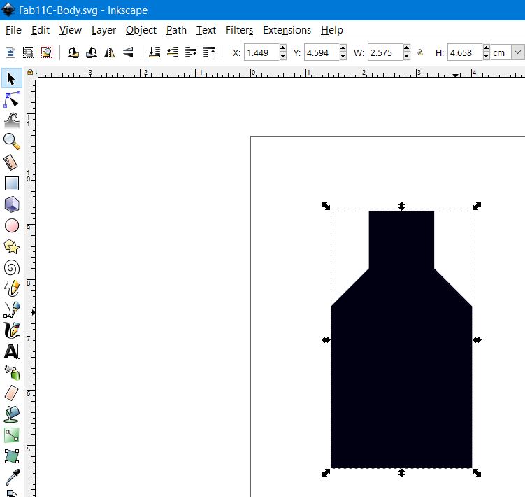
Then I imported that SVG file into OpenSCAD and scaled it up for the outside of the casing, and used the original for the negative of the board.
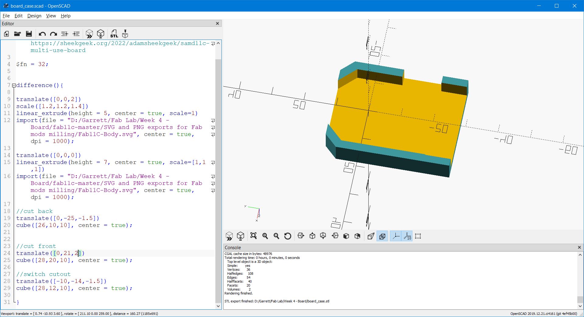
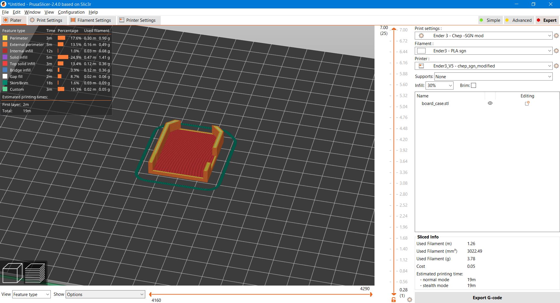
I saved this file as an STL and brought it into Prusa Slicer to prepare it for printing.
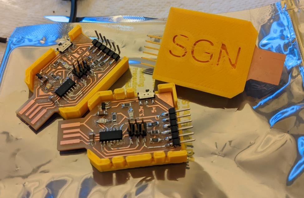
This case was a little tight, so I went back and scaled up the board footprint by about 4% to allow for more clearance. And printed again. Also added snaps, and a way to include your initials so that we can tell who’s board is who’s.
The OpenSCAD code for this case can be found here: Simple SAMD11C board programmer case.
And I documented all this, which takes more time than actually doing the things.
2/21 - Monday¶
Worked on researching some attiny412 info. Started thinking about how I would design the board I would need for the final project.
2/22 - Tuesday¶
Made a small blinky board from Neil’s design of an attiny412 blink board.
Milled it, stuffed it, programmed it, tested it. It blinks.
Found out that you needed to power up your board with something other than the Atmel ICE programmer to get it to actually work. Now they tell me.