13a. Input Devices Group Project
April 20 2022
Introduction
For this week, we needed to measure the digital and analog signals of our inputs devices.
Rotary Encoder
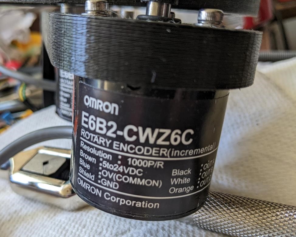
The first thing we chose to test was a rotary encoder that Garrett was using for his final project.
We had problems getting the attiny412 to succesfully read the rotary encoder, but we tried using an arduino and had success there.
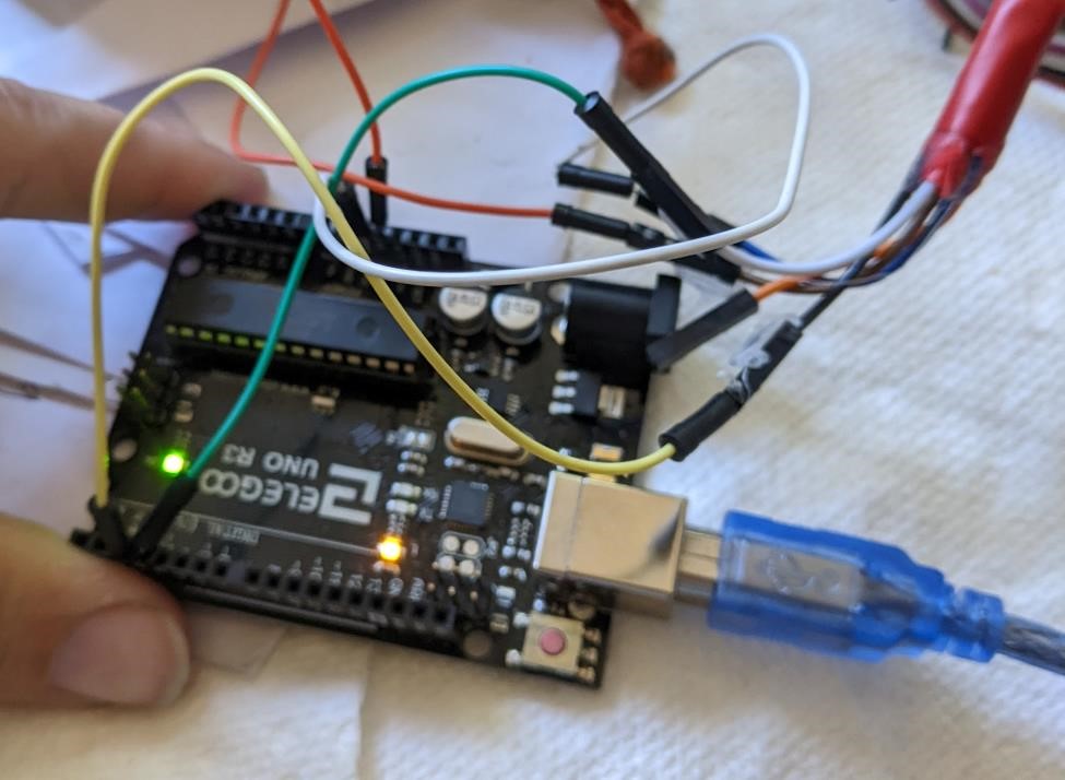
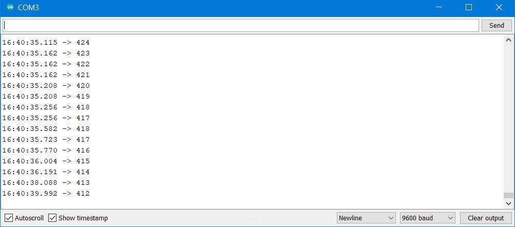
And we got the expected results of counting the pulses and determining the direction of the encoder.
We checked the power of the 5v line of the Attiny412 board, thinking that could be an issue, with a multimeter. It was reading 5.1v.
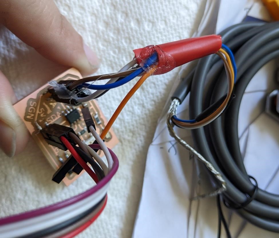
We hooked the power up to the rotary encoder, and then used an oscilloscope to the A and B pins of the rotary encoder, and you could see the pulses coming from the rotary encoder. However, I will say they did appear to be rather weak, only having about a 1v peak to peak signal.
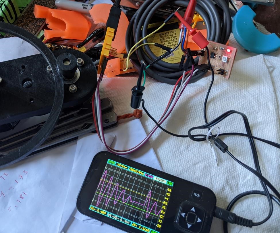
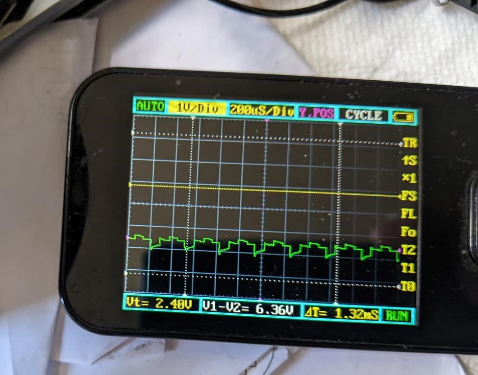
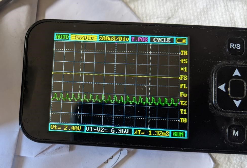
But as you can see from the images, there is a clear quadrature signal that can be seen in the oscilloscope as the rotary encoder is turned.
This is even more clear in the video:
We noticed something about this output (it’s the green line, ignore the purple line, it’s just a stupid background image.) The output is very weak. Even though it was read by the Arduino (runnin at 5v, with the encoder running at 5v.) The signal is less than 1v peak to peak (p-to-p)
We asked Denny about this and he asked me about the data sheet for this encoder. I had origninally looked on the Omron website for this, but I did not find one. We went back, and somewhat hidden away, we found the technical documentation talking about output signals.
(The PDF document is here: https://www.ia.omron.com/data_pdf/guide/34/rotary_tg_e_7_2.pdf )
And the Specifications of the encoders (https://www.ia.omron.com/products/family/487/specification.html)
And according to the spec’s, it’s a “NPN Open-collector output.” (https://learn.adafruit.com/transistors-101/open-collector)
Which apparently, according to Denny explains why the output signal was so low. And an easy way to fix this is to simply provide a pull-up resistor (1k may be enough) and this will improve the signal output.
We thought this was a great lesson, even if your system is working, hooking it up to a type of signal analyzer gives more information on your electronics. Just using an oscope to look at our encoder showed us that something was slightly off, and even though Garrett and Cori didn’t understand what was going on with this, we understood something was off and we were able to consult an expert (Denny) for more information on how to fix this issue.