3. Computer Aided design
Week 2 - 2/2/22
This week I spent too much time playing with software making generative art. Hey, but it’s a legitimate form of computer aided design.
2d CAD
MSPaint. Yes. Paint.
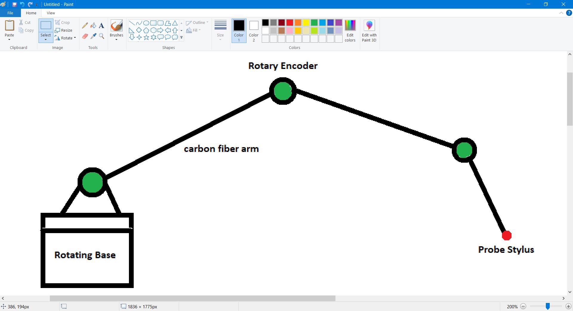
I played around with, what for me, was an early “CAD” program that I used in the past; MSPaint.
I used this to create my napkin sketch for my final project. While the dimensions are not exactly accurate, this is a form of computer aided design, and drawing in dimensions are the same as creating a blueprint that is not to scale.
But regardless of accuracy and beauty, it’s a quick way of getting ideas drawn out.
Inkscape
I spent much more time with Inkscape. Many of the 3d designs I have done below, I took screenshots of, and then moved them into Inkscape for editing and converted them to 2d drawings. These were then be used for the vinyl cutter or laser cutter (at least they will be next week.)
I’ve actually gone into more detail with these processes for the next assignment, found here: Unit 4 - Cutting This is because many of the specifics uses are for preparing these designs for laser cutting and vinyl cutting, and not for typical 2d design.
Here, the below image was a screenshot (saved as a .jpg) of a 3d design that was then converted to a raster format in order to cut it on the vinyl cutter.

This screenshot of inkscape shows a very similiar process.
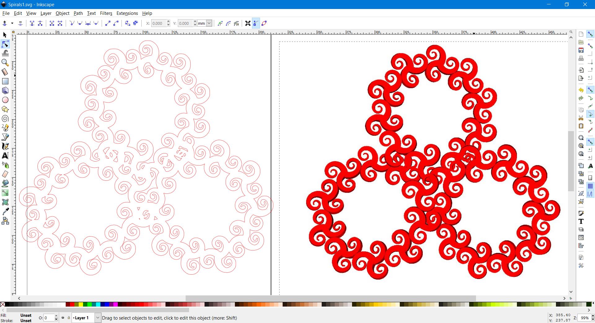
And another where I was changing a design, and converting it to an SVG.

While I find Inkscape very useful, especially with images, I’m more used to working in 3d CAD for designing parts.
3d CAD
I’ve been using OpenSCAD for a rough 3d sketch of my final project, so I wanted to start with software that I had no experience with. I wanted to try SolveSpace.
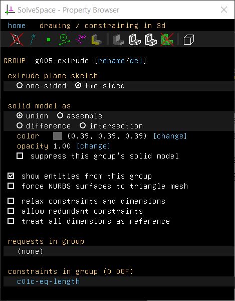
SolveSpace
I had heard about SolveSpace years ago, but have never had the chance to try it. Here was my chance. It should be noted that SolveSpace was not under development for a number of years, though there was an update in 2021.
Installing SolveSpace, first of all, there is no installation, you download an .exe and run. Nice and quick.
And then being completely lost with SolveSpace, I followed the introduction tutorial found here: https://solvespace.com/bracket.pl
I’m using a Windows laptop with a touchpad, and immediately I ran into problems. One of the first parts of the tutorial explains how to move your view around, and it uses the mouse wheel (middle button) to rotate the view. So immediately, rotating the view without a real mouse becomes difficult. (Touchpad’s can use a 3 finger touch as a ‘middle mouse button’ but using three fingers to swipe/drag, defaults to windows commands to hide windows, and turning this feature off, did not allow for click and drag using the middle mouse button.
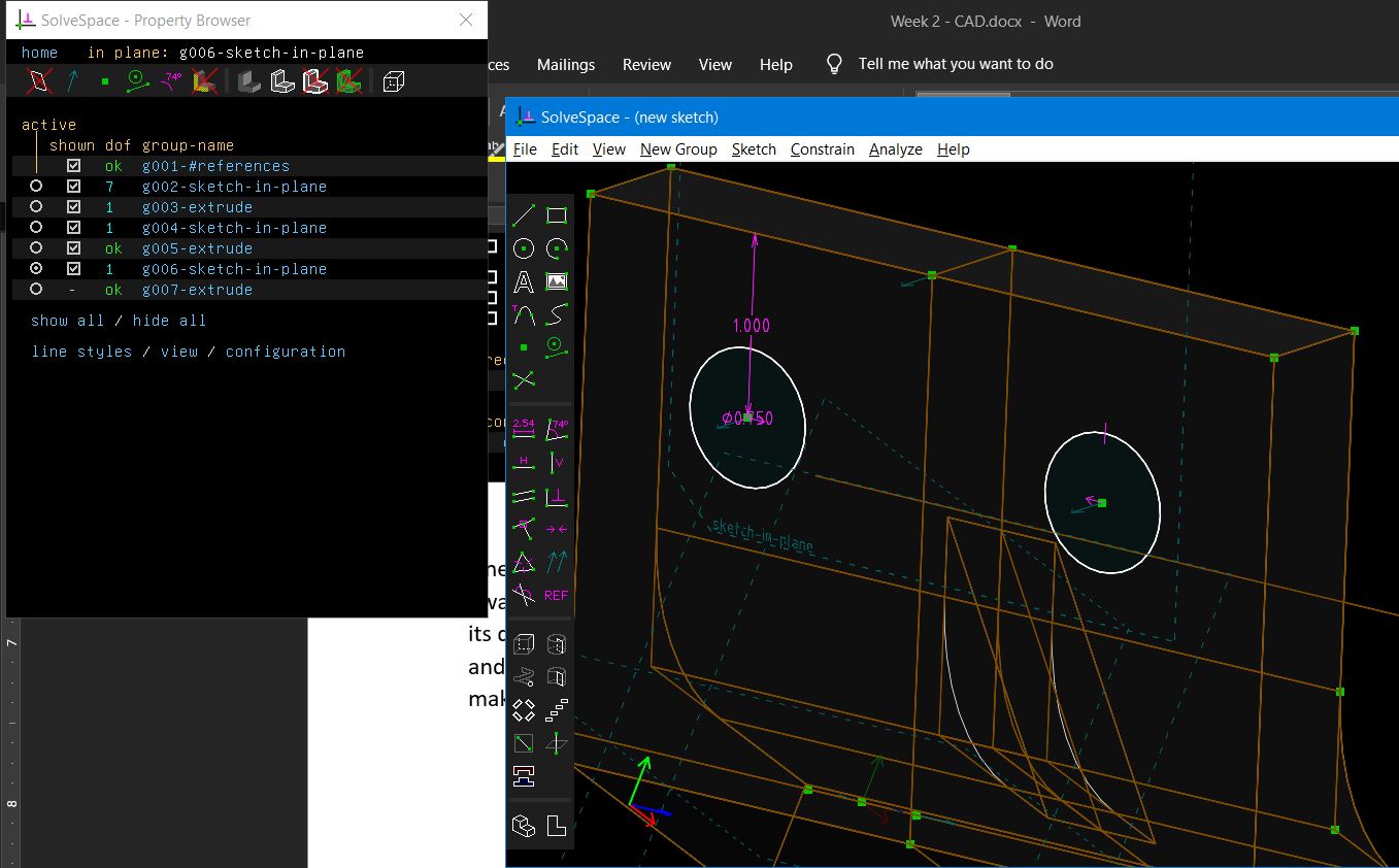
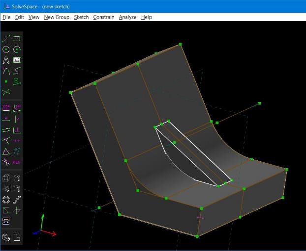
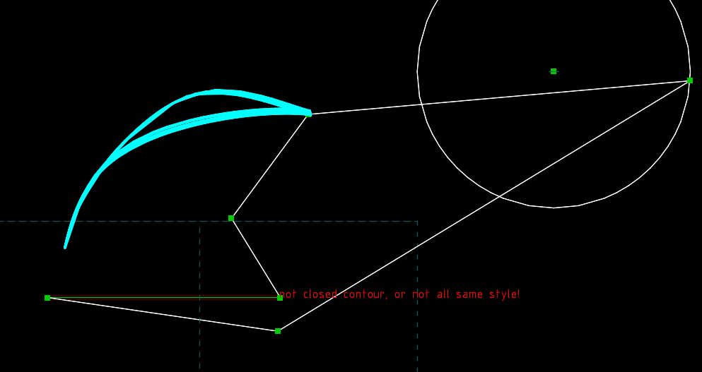
Following the tutorial I ended up very quickly with this shape:
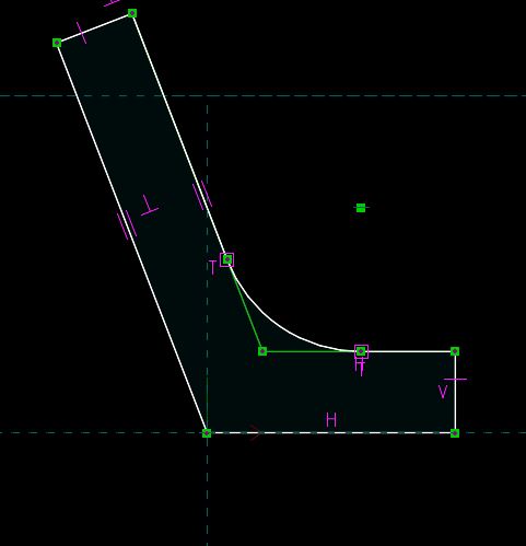
The important parts are the purple letters and shapes. They are each showing a constraint, a feature that the software is forcing to behave in a certain way. The “H” and “V” letters shown in purple are showing that these two lines which are next to the letters are either constrained to be Horizontal and Vertical, respectively. The other symbols: “-“ show the two lines are equivalent in length. “||” is parallelism.
As I was extruding this part, it became important to rotate the part. And that’s that for now. I couldn’t figure out how to rotate the part without a middle mouse button. No bueno. I went and got a mouse. Just so I could use SolveSpace.
After that, following the tutorial, I ran into other issues. For one, when I started drawing the second triangle (very simple.) I could not get it to extrude properly. This was because I had not created a new workplane to create this new part in. Once I figured this out, things started making more sense.
The interface is a bit old school, and isn’t quite as user friendly and intuitive as modern CAD programs, but it does have a consistency, and provides pop-up help.
One problem I ran into was adding dimensions to the part. This was more of my fault than the software. I was thinking that if I clicked on a diameter of the circle after I extruded it, I would be able to dimension its diameter. However, what I needed to do was go back to the previous sketch, before the extrusion and dimension the diameter, position, etc. in the sketch. Again, once I found this out, things began making sense.
At this point, I completed the tutorial, and I spent about 10 minutes figuring out how to modify and manipulate the part. Understanding how the constraints work in relation to one another, and most importantly, in which order to complete operations to get the proper effect in the software.
But the reason I wanted to try solvespace was not for the constraint system, which is nothing new to any other standard CAD system, but rather for it’s constraint solving for linkages.
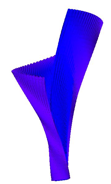
My First Linkage
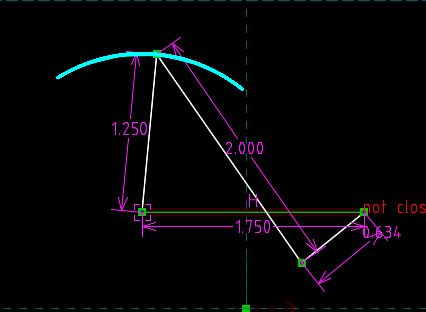
The above is just a basic 4 bar linkage. It was the process of learning how to create these linkages in Solvespace. The cyan (blue) curve line at top is showing the arc that is being traced by the point of the linkage as the point on the circle rotates around the circle. It simply goes back and forth, but I’ve got to start somewhere.
After getting the hang of creating linkages, I started to experiment a bit more. It became somewhat easy to create linkages in SolveSpace, but what was more difficult was to model items and then have these items fit with the linkages.
A “grab and push” linkage.
It goes back and forth, but it does go further “up” on one side of the circle, and as it gets closer to its end points, the speed at which the end of the linkage end moves, slows down.
I had fun creating these types of linkages and experimenting with them. It’s nice to be able to choose a point and see the path it travels as the linkage moves. While many other CAD programs are capable of making mechanical linkages (and more sophisticated ones at that.) It seems hard to beat how quickly and easily one can make linkages in SolveSpace. However, when it comes to features and abilities found in commercial CAD packages, SolveSpace starts showing its age and lack of development. But that said, I’m certainly no CAD expert, and certainly I haven’t spent enough time with SolveSpace to really learn it well and become truly proficient.
However, this inspired me to work with more linkages, using OpenSCAD, as you can see at the bottom of the page.
Structure Synth and MeshLab

(You’ll see the above pattern again next week for computer controlled cutting.)
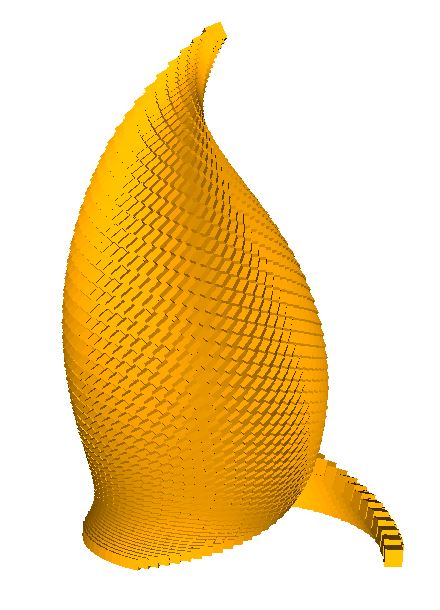
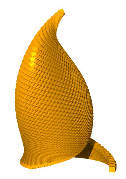
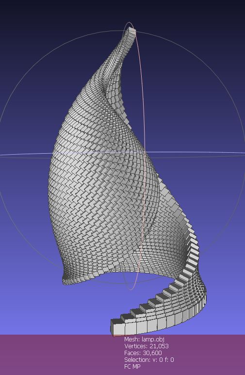
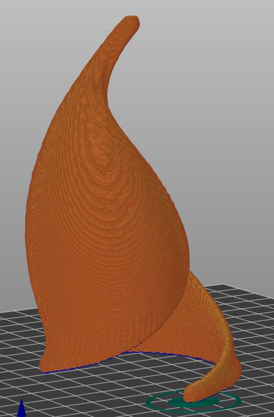
Next up was Structure Synth http://structuresynth.sourceforge.net/, a generative design software project. This is another piece of software I had heard about before, but never used. Sadly, this software seems to be abandonware, the last time it was updated was in 2010. That said, it’s a great piece of software for generative design. I spent hour and hours playing with it and MeshLab (more on MeshLab later.) The above image is just one very simple design I created with StructureSynth.
I really like what can be done with Rhino3d and Grasshopper. In my opinion it is one of the best combinations of the ability of a traditional CAD system, and mathematical, programmable system. But alas, I don’t have access to Rhino3d.
StructureSynth does not do traditional CAD, and it hasn’t been updated in 12 years, but it does some very neat generative design. It uses recursion and simple shapes and translations to build some fairly complex geometry.
For Instance:
With just a few lines of code, you can create incredibly complex structures.
The code for the above vase is simply:
// kitchen ware
//sgn jan 2022
set maxdepth 16000
set maxobjects 86000

set background #fff

50 * { x 0.7 rz 5 s 0.99 color blue } 20 * { y 1 ry 0.2 rz 3 hue 1 } r2

rule r1 md 44 {
{y 0.1 ry 0.4 rx 0.8 rz 1 s 0.99} r2
}

rule r2 md 40 {
{x 0.2 z 5 ry 0.3 rx 0.2 rz 4 s 1.005} r1
{s 3 3 5} box
}
However, they can only be exported as *.obj files. And while this format is open and common, my understanding it is used in more “artistic” modelling programs such as Maya, Alias, etc. In order to get it to a 3d printed STL file, I had to convert it. I followed a guide from an exceptional website: https://mathgrrl.com/hacktastic/2017/08/repair-and-prep-structure-synth-models/
MeshLab
This required using MeshLab https://www.meshlab.net/ Meshlab is an open source, and in my opinon, incredibly complex mesh editing software. It’s feature rich, but very unintuitive. Even simply selecting vertices and faces is much more difficult than one would think. I’m sure if you know how to use it properly however, it’s quite powerful.
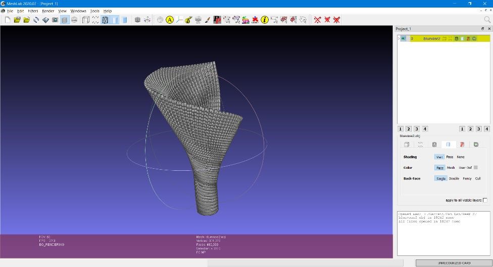
This is what you’ll see when you open and import a file into MeshLab.
Our goal is to open the file in the .obj format as save by StructureSynth, and turn it into an .stl so that we can later 3d print it. In order to do this however, was a bit of a learning curve, even with the help from the above “mathgrrl” website.
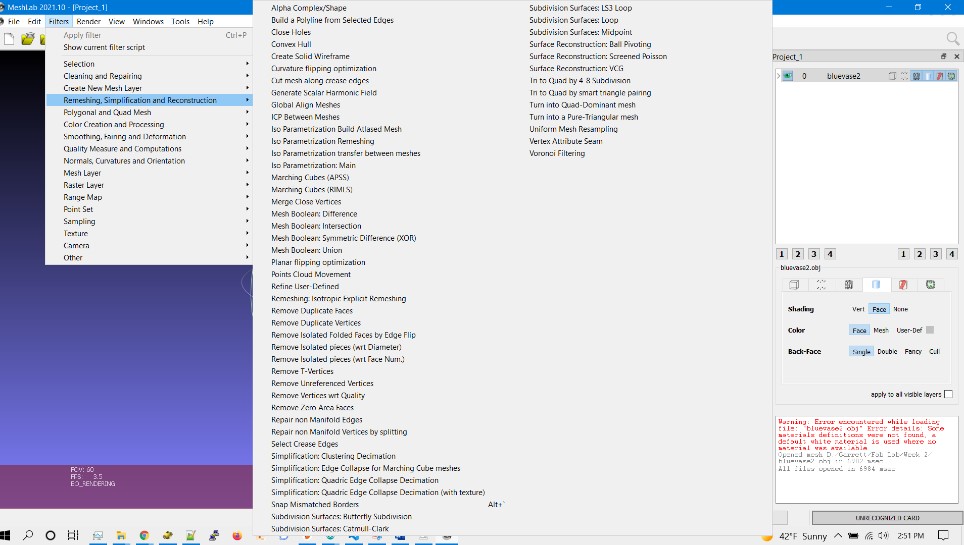
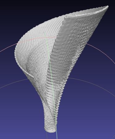
The above is a screenshot of all of the remeshing, simplification and reconstruction filters available for MeshLab. I hope you know the differences between them. And each one of them will have their own unique set of parameters. I think it helps to have a PhD in mathematics or computer science.
I spent a bunch of time (literally hours) guessing which filter to choose, and what numbers to use. I tried many different remeshing and smoothing algorithms. Many of them gave me poor results. Part of the reasons I had problem with this is because of how SurfaceSynth outputs its meshes. It does not do any Boolean operations or clean up internal faces/edges. If a model has internal vertices and faces that can not be seen, they are left there. This likely improves the performance of the software and is the reason it can create models so quickly, but when it comes time to edit the models in other software, these tens or hundreds of thousands of extra faces and vertices cause many problems.
I discovered this when working with the “vase.” Many times, I would try remeshing or some other method and I would get an error due to lack of memory. However, when I was able to find a remeshing operation (decimation) that removed many of these hidden vertices, performance of the software increased dramatically. And almost all the internal faces/vertices were removed making it easier to export the mesh as a watertight, error free STL. On the other hand, decimation and smoothing does case a reduction of resolution, sharp edges, and other features of the model. Like so many things, there are trade offs when using this method to clean up meshes.

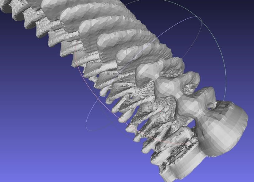
This is an internal view of one of the parts. You can see the hundreds of extra faces in just this one small section.
Parameters
To smooth out the model, I choose: Filters -> Remeshing, Simplification and Reconstruction -> Surface Reconstruction: Screened Poisson With the following parameters:
with the following results:
Not Too Good.
Using Reconstruction depth of 8 and minimum number of samples with pre-clean seemed to work well, and gave me an acceptable result. The following are the steps I took.
Remove non-manifold faces by splitting
Merge Close Vertices
Close Holes - 300
Turn into a Pure Triangular Mesh
Screened Poisson - default parameters
For interesting results, especially using StructureSynth models, try the Taubin Smooth filter, especially playing with the parameters (such as changing lambda to 0.2.)
Another Option to clean up internal structures
I googled and came acros this: https://meshlabstuff.blogspot.com/2009/04/how-to-remove-internal-faces-with.html
It provided a way to eliminate a large part of the internal structure of these models. It wasn’t perfect however, and there were other steps that needed to take place to get to what I wanted. However, this was a very helpful method.
The gist of the method is:
Filters -> Colors -> Ambient Occlusion
Filters -> Selection -> Select by vertex quality (have to choose which value, a bit of trial and error.  You want to select the max number of internal, without selecting outside vertices.)
Filters -> Selection -> Delete selected faces and vertices.
The numbers I selected left a hole in the bottom of the inner section (probably because the ambient occlusion is based on a light source, and that light source did not reach the bottom of this section. You can see here how also it thins out large sections of the base.
I then copied the model, did a remesh - screened poisson using default parameters. This created a poor resolution copy. This however closed the hole. These two layers were then combined using “combine visible layers.” Which ended with a much smaller model size, less vertices and faces, with a close hole, and a small decrease in quality.
However, in this particular model, I wanted the stem of the model to be hollow (like a stem vase) and this was no longer the case. I fixed it in Prusa Slicer by creating a negative volume (a cylinder), and placing it in the proper position. When you slice the model, these areas are empty, allowing the model to be closer to what I designed.
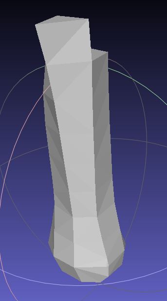
Another Example - “Lamp Shade”
Here’s another example, from start to finish, showing the steps from code to a final phyiscal object.
// lamp shade
//sgn jan 2022
set maxdepth 6000
set maxobjects 26000
set background #fff

50 * { x 1 rz 5 s 0.99 color orange } 1 * { y 1 ry 2 rz 3 hue 1 } r2

rule r1 md 50 {
{y 0.1 ry 0.4 rx 0.9 rz 0.2 s 0.99} r2
}

rule r2 md 70 {
{x 0.9 z 0.3 ry 0.5 rx 1 rz 5 s 1.009} r1
{s 1} box
}
With this result:
And StructureSynth has it’s own simplistic raytracer:
Following this, I wanted to simplify and smooth it in order to 3d print it. So I used MeshLab to go about doing this.
In Meshlab, this model is already a much simpler model, having only 30,000 faces.
I wanted to smooth the squares out, knowing that with a FDM printer, this small level of detail would be difficult to print, and would negatively affect the print quality as well as the final product.
following the steps in the previous section, I used Remeshing -> Surface Reconstruction: Screened Poisson, which gave me this:
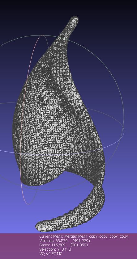
Note that this more than doubles the face count. The mesh is shown with the vertices. I exported this file as an .STL file and then imported it into Prusa Slicer software
Sliced with Prusa Slicer. Model was scaled 400% (115mm tall). 0.28mm layer height, 3 top, bottom and outside perimeters. 15% infill. Printed in PLA.
And Finally, a 3d print:
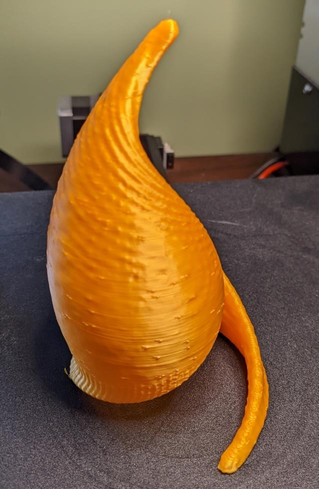
It came out okay. Could be a bit better. I’ve already found better ways to smooth it, with a better and quicker result.
The files from experimentation of Structure Synth obj models and the Meshlab files came to be over 500mbs, and even some of the STL files were over 5mb. I’ve left them off of the gitlab due to size constraints. However, if you’re interested, you can contact me. But with the ease of creating the files yourself from Structure Synth (as well as OpenSCAD below) it should be no problem to recreate these projects.
Onshape
I tried to sign up for an Onshape Education account (multiple times), but at the signup page, I got a spinning wheel of death, that never stopped. I tried with two browsers, neither of which worked. I’m not begging them to let me use their software. So much for OnShape.
2/10/22 Update: Finally was able to get an OnShape account.
Antimony – Another Fail.
On the lecture, Antimony seemed awesome. I was excited to give Antimony a try. However, it’s only compiled for MacOS, and the source code seems to only compile reliably for Mac and Linux from reading comments. I pulled out a Raspberry Pi 4 and found a Debian package of Antimony. Installed this using:
Sudo apt-get install antimony
And ran Antimony. Seg Fault. It seems it was failing to use Qt5.
The Error causing segfaults:
qeglplatformcontext failed to create context 3009
I tried to track down this issue, and it seems it has to do with Raspberry Pi 4’s, general issues with OpenGL on raspberry pi’s, and issues with Qt5.
This is a fairly new distribution of the Raspberry Pi linux distribution based off of Debian’s Bullseye (and as an aside, as I was working on this, the Raspberry Pi foundation officially released a 64 bit version of the OS. I was still using 32 bit as I tried to fix these issues however.)
I thought I would try compiling and installing Antimony myself: The author was kind enough to have a simple to follow build documentation here: https://github.com/mkeeter/antimony/blob/develop/BUILDING.md I followed the steps:
# Install dependencies
sudo apt install git build-essential libpng-dev python3-dev libboost-all-dev  libgl1-mesa-dev lemon flex qt5-default ninja-build cmake

(On some distros, you may need to install `libqt5opengl5` or `libqt5opengl5-dev` as well).

# Clone the repo
git clone https://github.com/mkeeter/antimony
cd antimony

# Make a build folder
mkdir build
cd build

# Build and launch the application
cmake -GNinja ..
ninja
./app/antimony
And after all of that, it segfaulted in the exact same way… And frankly, that’s the extent of my skills to figure out exactly what is going on. I have a feeling if I used a raspberry pi with an older Debian OS based on Buster, I may have gotten it to work, but that was a bit more work than I’m willing to put in for a piece of neat, but niche software. On to the next program.
UPDATE: Tried compiling it and installing it on an older raspberry pi 3b, running buster. No love.
OpenSCAD
I’ve been using OpenSCAD for a number of years now. I appreciate it’s relatively simple system, it’s programming like interface, and the ability to make designs quickly. There are a number of downsides to OpenSCAD, such as the lack of doing things that other CAD programs do easily, such as adding fillets. The lack of any graphical GUI for manipulating models is partly the point, but is a feature that occasionally would be nice. And while it works with variables, which are arguably as parametric as it gets, and are a form of constraints; the constraint system of a typical CAD program does not quite apply to OpenSCAD, and to get the similar behavior requires a much more mathematical understanding of the part and what you wish for it to do. If you don’t have these skills, then OpenSCAD while capable of amazing things, may be more difficult for the average user to get good results.
That said, I used OpenSCAD for the first rough 3d sketch of my final project, and I’ve been continually using it for design changes to this design.
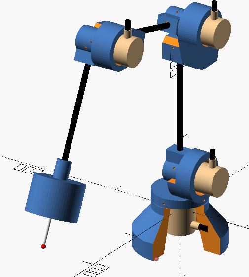
I’ve made the final design model as well as test pieces with OpenSCAD, and made key aspects of the designs parametric in case the design needs to be changed, bolts need to be resized, and other elements or components of the design change.
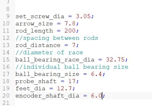
With these parameters, you can see some that are due to differences in 3d printers, and the ability to have self-threading bolts, such as the set_screw_dia which is the diameter of the set-screw holes for 6-32 threaded set screws throughout the design. Some is for the diameter of the arm rods that hold it all together, as well as their length.
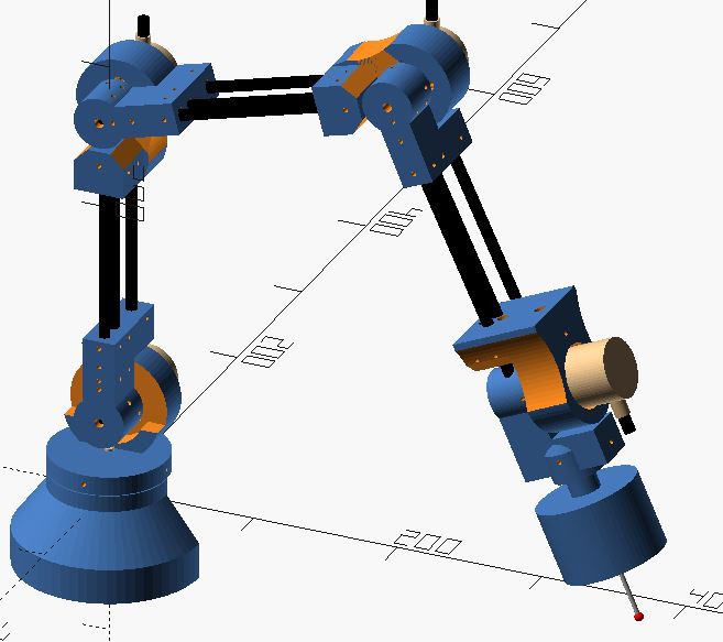
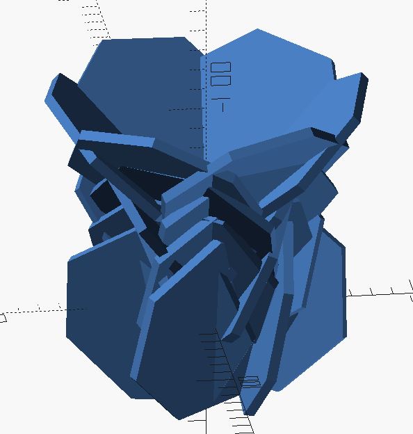
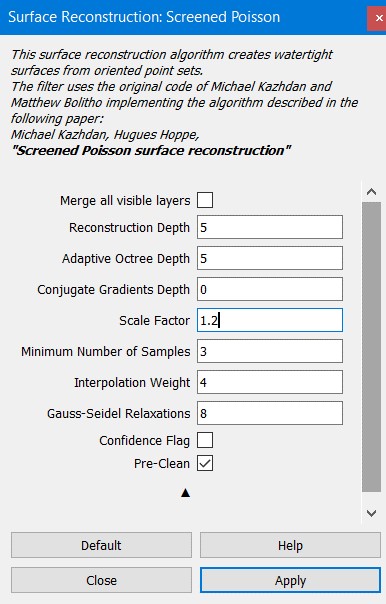
The current design of the final project. You can find the OpenSCAD code for this here: Arm Desgin as of 2-10-22.
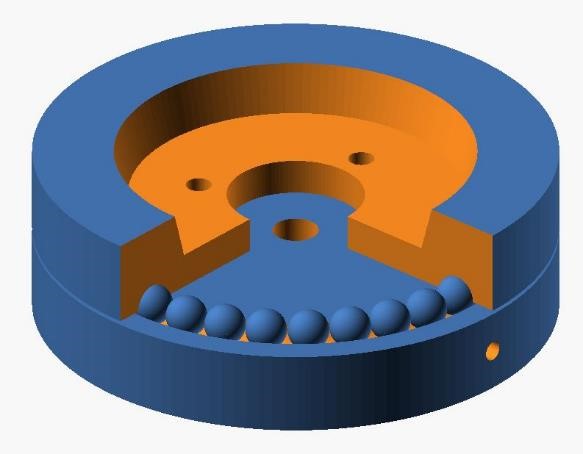
OpenSCAD 3d printed bearing test design.
But I also used OpenSCAD and the parameters to create a thrust bearing test piece. In this particular case, I needed to make the race (where the ball bearings ride) a specific diameter to fit as many equal balls with the smallest space between them as I can. As well as the correct diameter of the balls themselves. While I am using off the shelf POM ball bearings (0.250” or 6.35mm), 3d printers all have print tolerances, and this is made in order to get the best fit as possible.
This also included the diameter and the height of the counterbore for SHCS (should head cap screw) to make sure that their placement, as well as their depth was adequate.
If you look at the above parameters image, you can see that I used a ball bearing diameter of 6.4 mm and a ball race size of 32.75 mm. This allowed for 32 ball bearings total.
The 3d printed thrust bearing test article. One mistake I made was that I had made the center through hole a diameter of 0.250” (6.35mm) instead of 0.236” (6.0mm). This was easily corrected with the parameters, and will be corrected for all the other parts of this entity that have encoder shaft connections. The OpenSCAD file can be found here
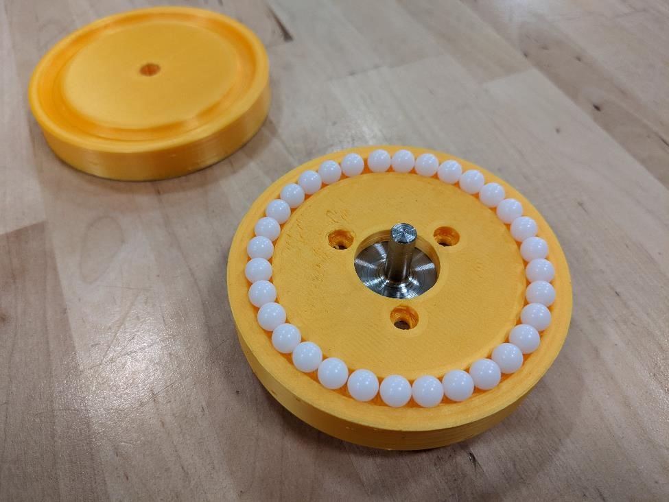
You can find the OpenSCAD code for this part here: OpenSCAD Ball bearing test
Other OpenSCAD designs
And I continued to work on various other OpenSCAD parametric designs.
Here’s a taste:
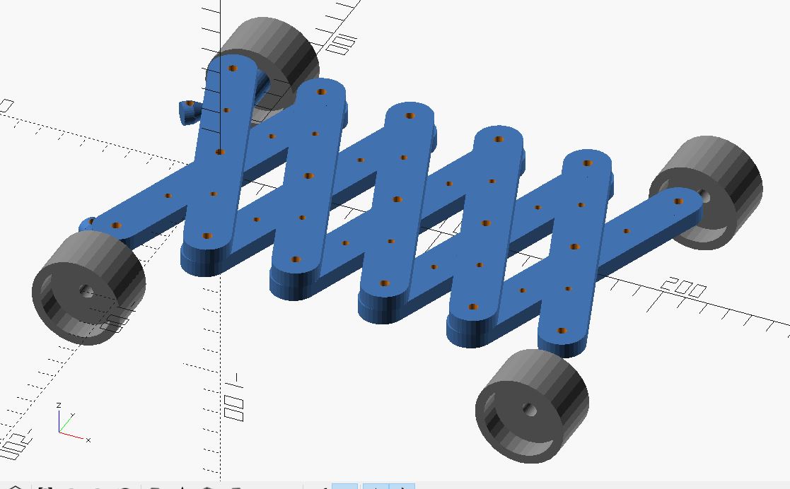
A scissor linkage, files for it are here
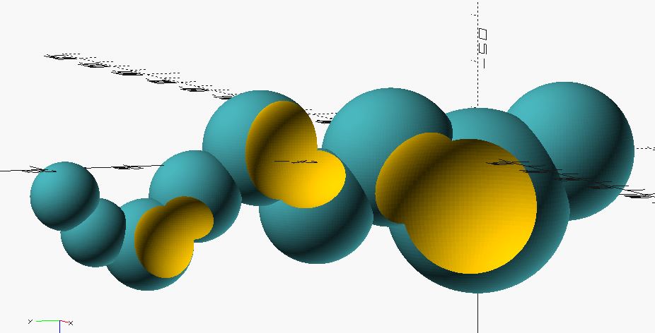
bubbles. See here for a voronoi experiment on this design.
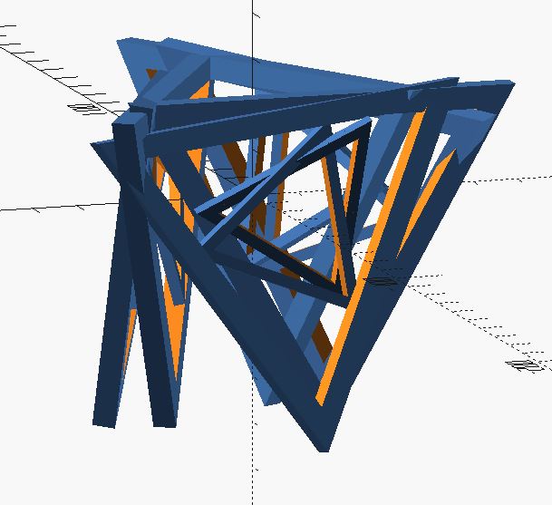
A triangular base for a table. Trying to figure out how to actually cut the joints to physically make it. That’s highly difficult as it is currently designed. OpenSCAD files can be found here
Something else… But change 1 number and it “closes up.” OpenSCAD file here
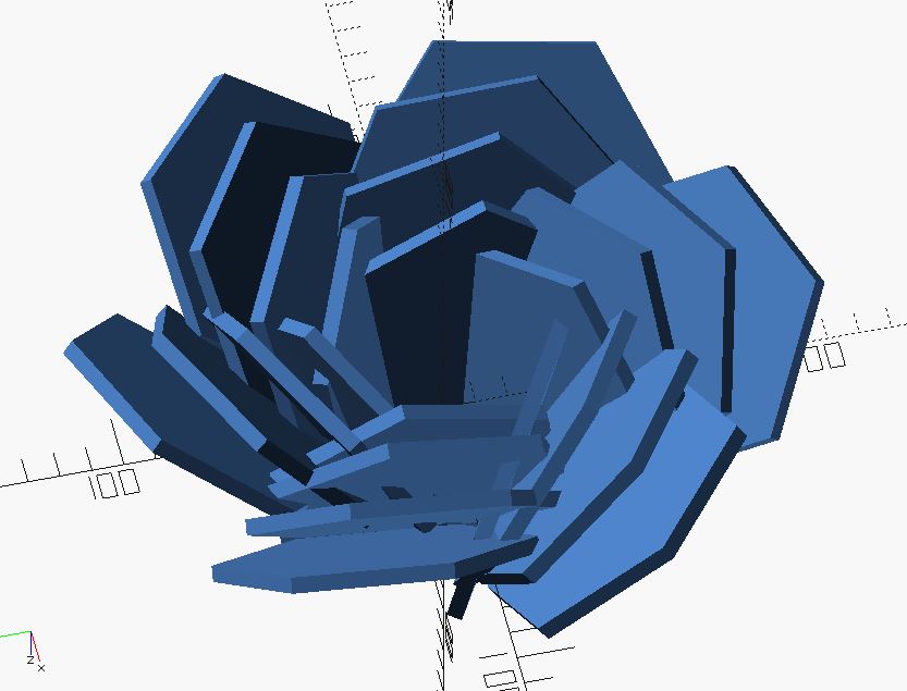
x changes from 3 to -21.