1 - Principles and Practices
Week 1 - 1/26/22
Project Digitialzing Arm
A digitizing arm utilizing a touch probe for metrology and reverse engineering.
Introduction
I’ve been interested in metrology for a number of years now. I find the precision and accuracy needed to build high quality parts, and to ensure that they meet stringent requirements fascinating. A modern method of measuring parts is using a Coordinate Measuring Machine (CMM). CMM’s are highly accurate, but also highly expensive. They’re common in the manufacturing world and labs, but less common in small shops. I would like to create a small digitizing arm that
There are two common types of CMM’s. One is a typically gantry style, that looks very similar to a wood router. Instead of having a spindle that cuts, it has a probe that touches and takes measurements of the specimen. The specimen is placed inside the CMM and measured within. This makes the CMM limited to the extent of the part that can fit within. They are usually built on granite surface plates, use air bearings, and move in a cartesian coordinate system (X, Y, Z plane). The sensors are glass scales. They are high accuracy, but are permanent installations (most require air compressor, some now do not require air.) with a high weight (they’re built on granite surface plates.) and high cost. ($70,000 and up.)
The other form is an arm style (sometimes referred too by a “Faro Arm” (though Faro is manufacturer of this arm.) This is a kinematic system that looks more like an industrial robot, with arms that have multiple degrees of freedom. Digitizing arms are more flexible in what they can measure, are typically based on rotary sensors and polar coordinate system. They typically have a low weight, the ability to be transportable, and can be moved while in use so they can be used to measure very large objects such as cars. Their accuracy tends to be less than a gantry style CMM, but they also cost less ($8000 and up.)
This project is designed to build a digitizing arm with a probe tip, and to see with a relatively small budget, how accurate they can be made.
Digitizing Arm
“Back of Napkin” sketch
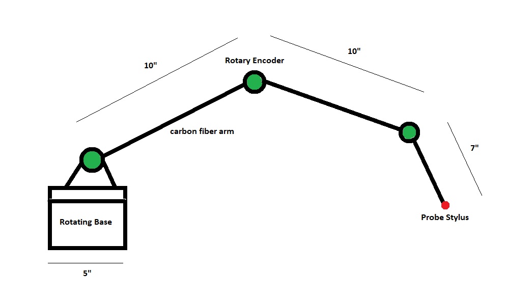
This is the very quick sketch I drew to get started on my project. It’s a simple sketch, as there isn’t much to the physical aspect (at least that I’m capable of free-hand drawing.)
It’s an arm consisting of 3 linkages, with rotary encoders at each joint, a rotating base that also includes a rotary encoder, and a touch probe stylus to touch the sample part. This data will be collected and sent to a PC for analysis.
Rough 3d Sketch
Because I can’t draw, I went to a 3d CAD system to help me better model out my design.
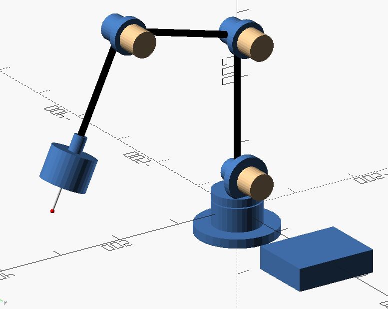
Shown: Blue = printed part, beige = Omron Rotary Encoders, Black = Carbon Fiber rods, probe and probe stylus shown at the end of the connected rods. Blue box on side is to hold electronics and the interface. 3d sketch made in OpenSCAD. Really ugly OpenSCAD code for this part can be found here: Arm
Design
This digitizing arm consists of 3 arms, each connected by a moveable joint attached to a rotating base, and with a touch probe attached to the end of the last arm. The joints are connected to quadrature rotary encoders which give an angular position of each joint. There is also a rotary encoder in the base, which allows for the rotary position of the arm to be captured. Finally, there will be a probe that detects any contacts with the part being measured. The data will be captured by an Arduino or similar microcontroller, and sent to a computer in order to capture a point cloud, that can then later be turned into a 3d model.
The arms will be created from a 0.300” (7.65 mm) carbon fiber arrow shaft. One of the benefits of carbon fiber is not just it’s stiffness and strength, but also, it’s low coefficient of thermal expansion.
The arm connectors will likely be 3d printed, and will consist of two pieces for each arm. One piece will hold the encoder, as well as connect to the previous rod. The other part will connect to the shaft of the encoder, and attach to another rod for each subsequent arm.
The base of the unit itself will consist of multiple 3d printed parts, and possibly a laser cut/machined wood base. This will have a fixed stand, with another encoder attached. The encoder will support a plate that holds the first arm rod, and the encoder for the arm. It will likely need an extra and larger bearing of some type around this entire base to help support and smooth the rotation of the arm. This is due to the weight of the entire arm being supported by the encoder without the extra bearing.
There will be a probe placed at the end of the arm to allow for automatic recognition when a part is touched. See the below section for more information on the probe itself.
Finally, there will be an electronics enclosure that will have the wiring from the probe, encoders, etc. going in, and have the connection to power and/or computer coming out. This will either be 3d printed or laser cut out of thin plywood.
Design Goals:
This unit will be designed to be accurate, repeatable, and inexpensive. I also want the unit to be sturdy, and to be able to take abuse from inexperience users. The unit needs to have an accuracy of 0.006” (0.150 mm) or greater, and a repeatability of 0.003” or better. These are actually fairly stringent for a digitizer arm, and even more so for a DIY arm. However, this is a target, and in reality, if I can get anywhere near these goals, I will be happy.
In order to reach these goals, I’ll have to ensure that the stiffness of the arms, base and all the connections are very rigid. Any flex can be a major source of error, and with multiple connections, the error of one connection will be magnified to the next. Carbon fiber rods will help, but the 0.300” diameter may not be large enough over the given length. This is also a reason to keep weight down to a minimum on the end of the arm. The most likely issue will be the 3d printed connectors and the base of the unit. Because of their being made of plastic, they’ll need to be well designed and printed with large infill. Even this may not be enough to ensure their rigidity.
In order to maintain repeatability, especially if the unit is being moved, I will try and avoid using any wood in this project due to its high propensity to be influenced by humidity and temperature. Plastics can also be affected by humidity, but not to the same extent as non-stabilized wood you’re typically use for this type of project.
Notes and Challenges for Arm
While designing this part and sketching it out, I thought of a number things, such as:
-
Will need a good way to keep base down. High weight is obvious, but would like to keep weight down. Large flat base would also work, but would cause issues with usage. Could always bolt it to a surface plate, but that makes It less portable. Maybe suction cups? Good old C-clamps?
-
Rotary Encoder wires are about 5mm in diameter with sheathes. Won’t fit through current small diameter carbon fiber tubing. Would need to invest /re-engineer for much larger tubing. The wiring is going to be very unclean. I could make a sleeve around the entire part to hide wiring, but this is a less elegant solution, but probably best solution given constraints.
-
Design currently relies on the internal bearings of the Rotary Encoders for movement. This could cause multiple issues. First, relying on these bearings to support weight of the entire system. Second, relying on bearings (which retain the encoding wheel in precise position) could cause movement of wheel and thus inaccuracy of measurements. If we switch away from rotary encoders (optical mouse sensors), then we need to add bearings.
-
Adding the above bearings of rotary encoder may increase weight. The bottom base, x-y encoder is likely to need a larger bearing for support to keep it from leaning.
-
The specific Omron encoders are now very expensive, at around $500 for a 1000 ppr (pulse per revolution, essentially a measurement of resolution.) It’s likely I will use a cheap Chinese knockoff of these style optical encoders that are closer to $30 a piece.
-
The probe on the end of the arm is currently very large based on prototypes. To be more useful, (to fit in smaller areas without the probe body getting in the way) it would be necessary to shrink the probe body.
-
Moving the probe tip is a large issue. First, simple probes are moved in 1 axis at a time, and this allows easy interpolation of point. With multi-axis/polar movement of probe, will be much more difficult to determine where the probe tip actually makes contact. With cartesian CMM’s, probes usually deal with multi-axis movement by the direction they retreat from the part after triggering probe sensor. This movement after the probe goes back to un-triggered helps the software determine which way to compensate for the probe tip. This solution, however, requires better programming skills than I have.
Touch Probe
Rough Sketch
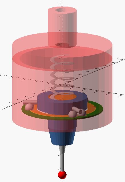
This is a rough outline of the basics of a touch probe. Created using OpenSCAD. Really ugly OpenSCAD code for this part can be found here: touch probe
Design - Touch Probe
This touch probe is based on the very early design of touch probes. It uses three sets of two ball bearings arranged 120 degrees from each other, with a metal rod resting the sets of balls. The rods are part of an insulating piece that also holds the probe tip at the bottom. This piece is held against the ball bearings by a low force spring. When at rest, these rods resting on two ball bearings (with each set connected to one another) completes a circuit. If the probe tip/stylus is moved, it will lift a metal rod, and the circuit is broken indicating a “touch.”
You can buy a touch probe for CNC mills for around $200. However, I wish to build my own for this project. I believe it is possible to build an accurate and repeatable touch probe, but it typically is necessary to have the high accuracy and surface finish of machined parts. Using 3d printers makes the creation of a touch probe more difficult (though certainly not impossible).
Touch Probe will have a 3d printed Main Body and Lid, a PCB “base plate” to hold six ¼” steel ball bearings (steel must be solderable, this is hard than it seems with ball bearings if they’re chromed, also due to high surface finish as well as high temperature sink. There is a special type of solder to help with this issue.)
The PCB can be easily and precisely milled to hold the ball bearings and to allow electrical connections to the bearings, as well as out to electronics. Spring (with adjustment screw at top) will provide tension to keep steel conductive rods between ball bearings unless a force is applied to probe tip. Probe tip will have three set screws in bottom of main case, that will hold up the pcb plate holding the bearings to allow for centering of probe tip. The three rod insulator and probe stylus/tip holder will be machined or 3d printed, and then an off the shelf ruby tipped probe stylus will be installed.
The electronics of the probe will consist of a simple de-bouncing circuit, a 5v led, and possibly 2 buttons to allow for control of the software (ie, one button to turn on probing, one to turn it off, or to cancel an inadvertent touch.)
Notes and challenges for touch probe:
- Like the arm itself, trying to make this reliable, repeatable, precise, and accurate are key, but may be difficult to reach goals that are sub 0.002” (0.050 mm).
- The three rod style probes are known to register “touches” with inconsistent pressure based on the direction that the touch probe tip is pushed. This is the nature of the system. Calibration helps with this. (see this paper for a reference and more information on strain gauges used in probes: https://resources.renishaw.com/en/details/technical-note-renishaws-strain-gauge-probing-technology--130 )
- Will need a way to zero and center the touch probe tip. “Easy” with a turning spindle and high accuracy dial test indicator. (Easy as in setup is easy, dialing it in, not so much.)
- Will need a way to calibrate the touch probe. A typical Ball Gauge on a mount, same as cartesian CMM may work well enough.
- Need to watch out for bouncing button issues of contacts – may need a debounce button setup https://docs.arduino.cc/built-in-examples/digital/Debounce
- Will need a 5v power supply for LED for contact notice. Helpful ui.
- If I add buttons, will need to add electronics, wiring for these buttons as well.
- Will want to shrink size dramatically, allow for larger maneuverability and ability to measure objects. This design used easy to source 1/4” ball bearings and 1/8” steel dowel rods, may want to switch to smaller diameter balls and rods.
Other Challenges
Software, software, software. I can not program, so the idea of getting the data from the arm into software is an unknown for me. And to be able to accurately capture this data in order to turn it into a 3d model map seems incredibly difficult to me. In the same vein, this is not an cartesian coordinate system (XYZ) with fairly simple way to determine location, but rather is going to require an understanding of kinematics and polar coordinate math. Yikes!
There are going to be questions concerning the mechanics and geometry of the arms. May require offsetting arms side to side. Need to make sure there is no slop in bearings (regardless of using encoders for the bearings or not.) Also, the strength of 3d printed parts to not allow flex of the arms. All of these will can create inaccuracy.
Finally; unknown unknowns. I don’t know what I don’t know yet. And I don’t know a lot.
Manufacturing Processes
3d printing is an obvious large part of the physical parts of this build. The most likely parts that will be 3d printed are the rod and arm connectors, the swivel base, some of the touch probe internal parts.
There will also be CNC machined parts (most likely made from Aluminum or steel). Especially the base of the unit, and the body of the touch probe. Some of the internal and precise touch probe parts will likely be machined from plastic, as 3d printing may not afford the necessary tolerances.
The electronics will be based around a modified arduino board and/or Attiny85 boards, and be milled out of copper clad pcb. I’ll be soldering them and preparing them to be connecting to the sensors as well as one another.
The sensors for the arm positions are based off rotary encoders, but I am most likely going to attempt to create other sensors to replace/accentuate the rotary encoders. The sensor for the touch probe is going to be a kinematic, mechanical switch.
The output will be data that is sent through both an LED’s (for a “touch” on the probe tip). The data of the touch, and relative location of the probe will be displayed on an small LCD.
The data for the arm position and touch probe points will be output to a local computer, where it will be translated via software into Cartesian coordinates and mapped into a 3d environment as point cloud.
Material and Parts:
DIY parts:
Many parts can be 3d printed.
- Base, arm connections, encoder holders, probe section, etc.
- The plate for ball bearings holder for probe can be created as a pcb.
Off the Shelf Parts:
For the Digitizing Arm:
- 4 Omron Incremental Rotary Encoders 1000 ppr (E6B2-CWZ6C) (I have 2 of these, I’m 99% sure they’re counterfeit. I bought them off ebay a few years ago for about $30 each. A google search just revealed they are being sold for $530 from Newark.) https://www.ia.omron.com/product/item/2450/
- Carbon Fiber Arrow Shaft (0.300” (7.65mm) diameter, 31” length)– cheap after hunting season.
- 50 POM ball bearings (for ball bearing system on base.)
- assorted hardware, set screws, nuts/bolts (30 m3 x 8mm SHCS, 20, 6-32 x 1/8” set screws).
- 4 Attiny85’s and support electronics for encoder positioning data collection.
- One AVR and support electronics for DIY arduino
For the Touch Probe:
- 1/8” diameter, 1” long dowel pins - 6
- ¼” ball bearings (non-chrome plated, 52200 steel may be best.)- 12
- ¾” diameter, 1” low force spring - 1
- Renishaw Probe Stylus (A -5000 – whatever) - 1
- Assorted hardware, set screws, nuts/bolts
Electronics:
There are 4 rotary encoders, which require multiple inputs due to quadrature setup. (maybe more if we use the 1 rev counter). The plan was to use an Arduino, but this will quickly max out the inputs available. An Arduino Mega would work, but there are other options. A common option is a MCP23017 I2C GPIO expander. With this chip, you can use I2C to allow for more inputs to an Arduino.
The Touch probe will have at least 1 signal connection, and possibly 3 if two buttons are included. These will be also connected with an arduino for signal connection.
It may be necessary to use ATTiny85’s to connect to each encoder, and then connect each of these to a motherboard arduino. I’m still researching and trying to figure out what methods to use here. Which one of these methods will work? Which will be the most efficient, which will be the most reliable, etc.
Software:
Your guess is as good as mine. Though probably Processing, as a number of other similar designs and projects are using processing to seemingly good effect. I’ve never used Processing before, so this will be another hurdle to leap.
The software should be able to take data from the digitizing arm and convert it to cartesian coordinates. As data come in through the electrical connection, touches and touch probe will trigger the software to grab the data from each of the rotary encoders, and their position. The software will then convert the data from the arm’s rotational positions for each joint of the arm (in a polar coordinate system) and then convert these into positions in a cartesian coordinate system. (That sounds easy! I have no idea what I’m doing!)
The data should then hopefully be able to be mapped into a 3d space and show the location of each “touches” of the probe and provide a representation of these in a 3d point cloud, that can then be used for further processing in other software.
Right now, I have no idea how to do any of this.
Testing
As with any type of metrology equipment, if it’s not tested and calibrated, it’s not much use. I will need to find a way to test the accuracy and precision (repeatability) of this arm when it is finished.
While I’m still to think of proper ways to do this, I believe I can start by testing with gage blocks of known lengths, and ball gages of known sizes, as well as using 1-2-3 blocks and other precision equipment to test with. This will at least give me some indication of basic accuracy. Further tests will be created for examining other aspects of the arm at a later date.
Future Goals
These are things that I’m sure I will not have time to do, but things I would really like to happen (or at least experiment) at a later date.
- Better Software
- Extra degree of freedom at base of probe tip to allow it to rotate.
- Moveable Base – put optical mouse in base, to allow for measurements around a larger part (would necessitate a large surface plate for high accuracy of course.)
- 3d depth camera on arm to allow for more precise measurements using a depth camera and 3d scanning.
- Currently as designed, the arm is not self-supporting. It would be nice to have this feature. Maybe add springs? (think desk lamp)
- higher accuracy, less inexpensive system to capture positions of arms than industrial/commercial rotary encoders.
- Strain Gauge load cell used for the touch probe. This should allow higher accuracy, and simpler design. But requires more complex electronics, and has a number of design challenges of it’s own.
Prior Art
I have to say; before doing any research, I started sketching the design based off of what I knew of rotary encoders and digitizing arms/cmm’s/touch probes. You’re not supposed to do that, but I did it anyways. I got excited and I have fun designing things. Afterwards I started to look for prior art and other DIY digitizer arms. Imagine my embarrassment when one of the very first to appear was one from a previous Fab Academy. Oh well.
Digitizing Arms prior designs:
https://fablab.ruc.dk/diy-digitizer/
http://blog.dzl.dk/2018/08/21/3d-digitizer/
- I believe this is just an update on the fab lab project. Which includes a turn table.
- Excellent resource on how he found polar coordinates.
- Github for project: https://github.com/dzlonline/3D_digitizer2
https://www.thingiverse.com/thing:2882172
- I like the way that he added the weight, as well as the large ball bearing around the top of the base. I had previously thought of the bearing, but the weight is a good idea.
https://forum.makerforums.info/t/ccm-digitizing-arm-5-axis-faro-arm/78981
- Github for project: https://github.com/BL-Shopwork/CCM-Arm
Touch Probe Prior Art
Touch probe for small and diy CNC machines are common projects. I had previously created a touch probe, and so was aware of many of the designs already out there. These are some of the many resources available, and from which I have gotten information and ideas on how to design and construct my touch probe.
-
http://fadedbits.com/2011/02/touchprobe/
This is the probe that I’ve essentially based my entire design around. I think this is a very well designed and constructed probe.
-
https://www.instructables.com/CNC-Manual-Touch-Probe/
This is another design that was incredibly helpful. Very detailed instructions and gave me many ideas on the actual manufacturing. This also helped with the simple electronics and led. More information here: https://www.homemadetools.net/forum/homemade-renishaw-style-touch-probe-73121
-
https://lowpower.io/blog/introduccion-al-3d-touch-probe-para-cnc/
More information here: https://hackaday.io/project/168349-3d-touch-probe Where I stole the idea for the PCB ball bearing plate. This link also has links to other great videos on touch probes.
-
https://lukse.lt/uzrasai/2015-05-precise-steel-touch-probe-for-cnc-machines-routers/
I enjoy the design aesthetic.
-
https://forum.v1engineering.com/t/home-made-3d-digitizing-probe/18278/8
New to me, but very interesting design.
-
https://www.youtube.com/watch?v=_ZDlyLI_jbc
I love the clear case and LED
-
https://forum.duet3d.com/topic/8685/3d-scanning-a-2-coin-with-3d-printer-and-diy-touch-probe
This is just something different to throw in here. Showing using a tiny probe and 3d printer for a more “scanning” probe style setup.