11a. Output Devices Group Project
March 30, 2022
This week we looked at the power consumption of board we built in the Electrical Engineering Technology Lab at Central Piedmont Community College.
We looked at Garrett’s Neopixel board that he created for output week, and measured it’s power.
Denny Leak is an electrical engineer, and was the brains behind this week’s group project, to Garrett and Cori’s relief.
Denny first started by showing us one of his boards that he uses to teach students as well as to experiment with different ideas he has.
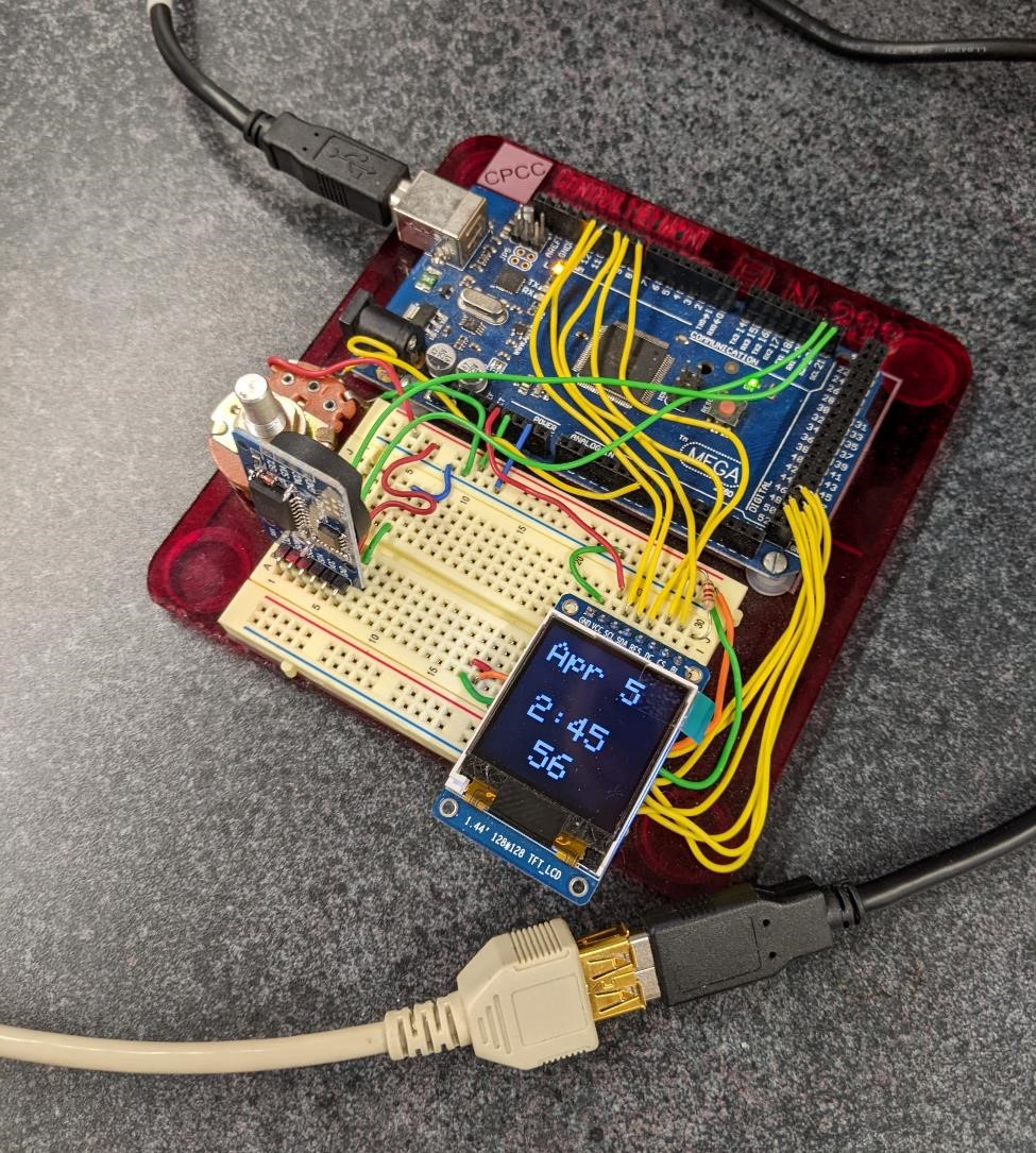
Here’s his board, which is currently set up as a digital clock, using an arduino, an LCD display, and a Real Time Clock board with a battery to keep track of time when the board itself isn’t being powered.
The Tutorial
The next thing that Denny shared with the group was Ohm’s Law which describes the relationship between current, voltage, and resistance.
Garrett never really quite understood Ohm’s Law, so this was a very helpful tutorial, and while he’s got a few things to learn before diving into electrical engineering, it really helped to make electronics make just a little bit more sense.
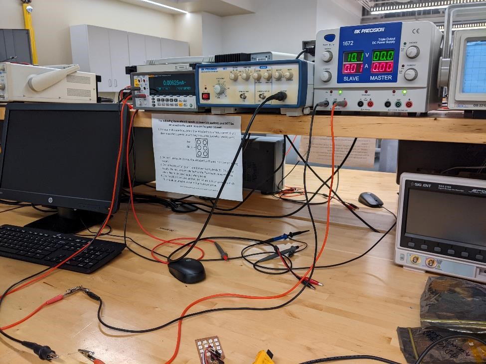
Here you can see Denny explaining the relationship between supplying 10volts through a 1k Ohm resistor and measuring the current with a multimeter.
This setup is very simple to re-create.
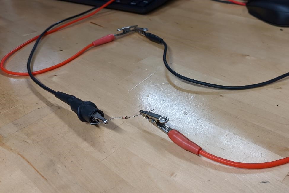
It consisted of the power supply set to 10 volts, with the positive ground being connected to one side of the 1K ohm resistor, and the negative lead being connected to the other side of the resistor.
Then, the multimeter clips are connected to each side of the resistor in the same manner.
You can then take Ohm’s law, I = V/R (With I being Current, V is Voltage, and R being Resistance.) and with 10V/1000 ohms, you should see about 10 milliamps of current.
And sure enough…
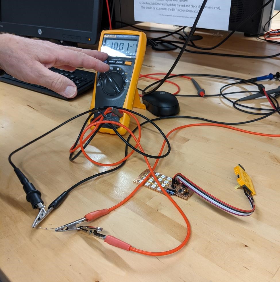
It measured exactly what we had predicted. 10mA.
Measuring a 16 Neopixel Board
After getting a basic understanding of what Ohm’s law meant in real world applications, it was time to measure an actual board.
We used the attiny412 board with 16 neopixels designed by Garrett.
![]()
This board is fairly basic, but with the inclusion of 16 neopixels, which according to Adafruit’s Uberguide to Neopixels can utilize a max of 60mA a piece when they are turned on full power (and produce a white color).
With 16 neopixels, that could be be almost 1A of current consumed by this board. That would be more than can be supplied by many USB power ports, and could be an issue. However, that is a worst case scenario, and they offer that 20mA is probably about the average type of usage you would typically see. But again, this largely depends on how you program your neopixels to behave.
As you can see in the below video, this board was programmed to have a “wave” of pixels that appeared one after another, and disappeared one after the other. Also, because the pixels are so bright, this neopixels are only at about 1/5th of their total power output. They’re also a greenish/blueish color, and do not use much of the red leds.
Make the board connections
While we used a very similar setup to the previous board, we had to make some connection changes. We weren’t just measuring the current through a resistor, but an entire circuit board. This required a slightly different setup.
This board was powered from the Adam Harris designed programmer circuit, which was being powered by a USB power brick. The circuit was running at 5v.
The setup had the 5v cable coming from the power of the programming board, to an alligator clip that was connected to the multimeter, through the multimeter to an alligator clip connected to another wire that was then fed into the neopixel board. The ground was connected directly from the programming board to the neopixel board.
Denny noted that an analog meter would have been better for measuring the current, but the multimeter was what we had.
![]()
![]()
![]()
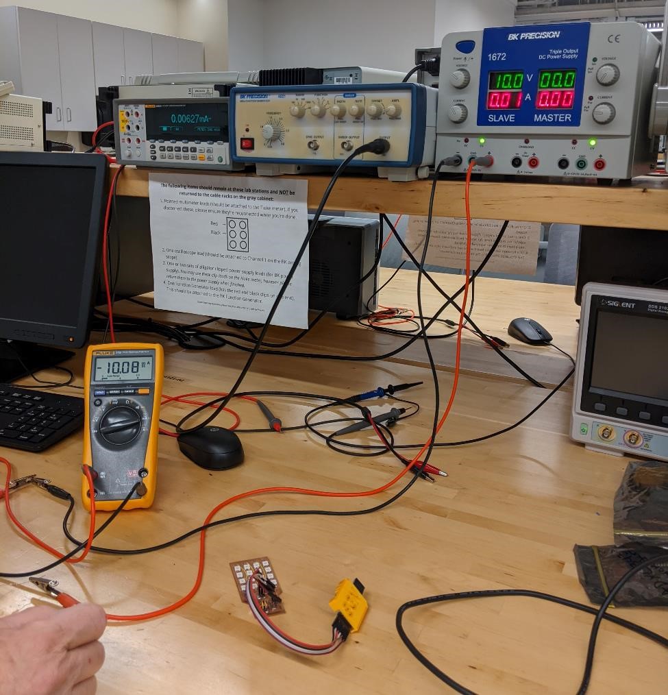
And what we noticed was exactly what you would expect when a number of LED’s are constantly turning on and then turning off. A measure of current that rose and then that fell.
It seemed to move from 15mA at the lowest, and with most of the LED’s off, to 20mA with all the led’s lit.
While we weren’t able to get exact readings with the equipment we had, it appeared that the average was about 17mA.
We could then take this information to figure out what the actual power consumption was.
Again, thanks to Denny, we knew that Watt (W) = Voltage (V) x Current (A).
We could then take the voltage, 5v and multiply it by 17mA to get 85mW’s of power output.
And with that, we learned a decent amount of how to find current, a bit about shunt resistors, and plenty of other practical aspects of electronics.
References
Denny Leak was our reference.