5. Group Project - Board Production
2-24-22
Milling the test piece
We milled a test piece based off the image that Neil showed in class, the “thousandths of an inch” piece.
Equipment and Software
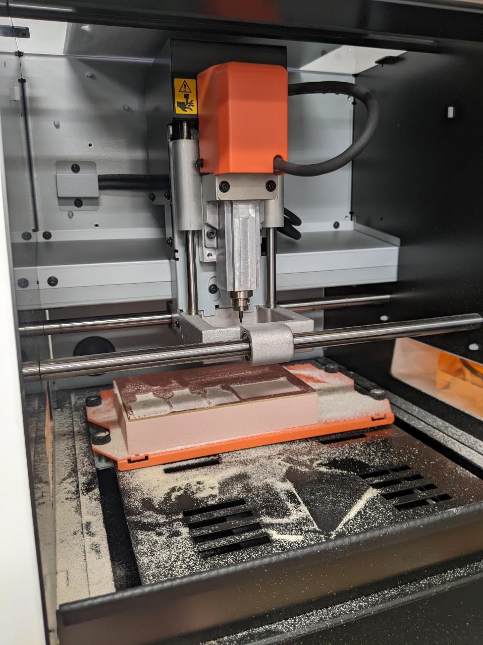
We used a Roland SRM 20 mini mill. It has a small footprint, a decent work area, and an 8000 rpm spindle. This mill was setup with a ~1 inch spoil board, on which we used double sided tape to stick single sided 1.2mm FR1 pcb material.
The SRM 20 ready to Go.
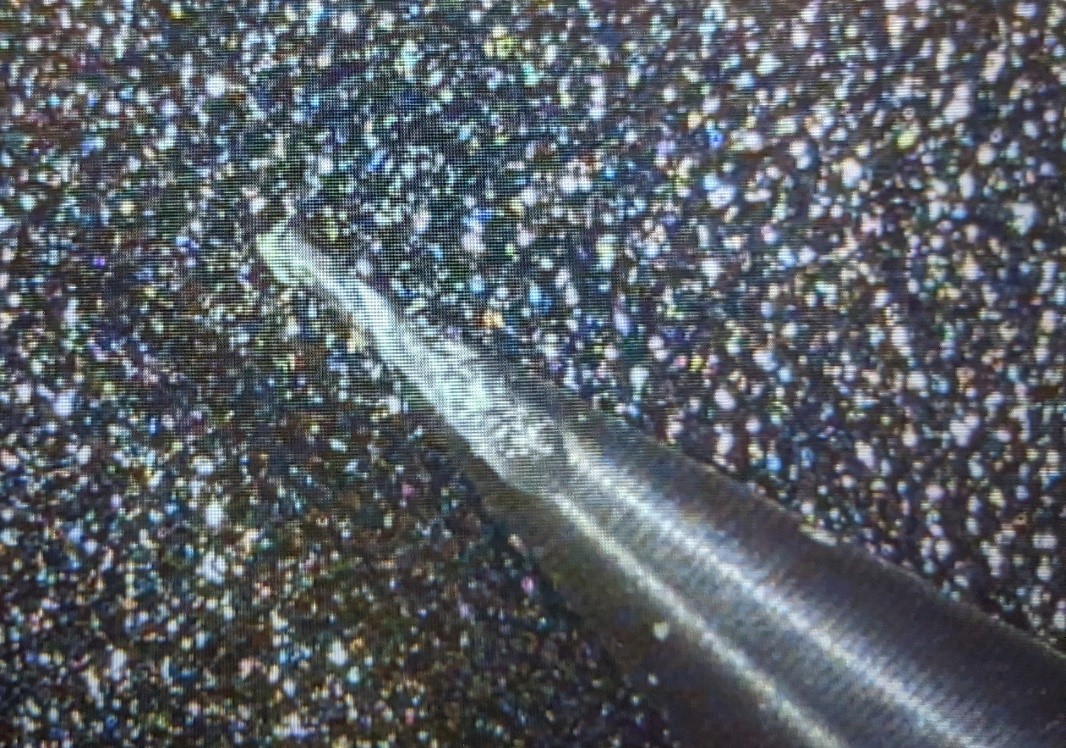
We used two endmills, a 1/64” 2 flute square end mill for cutting traces and a 1/32” for cutting the board from the rest of the PCB material.
Image of the tip of the 1/64” endmill, magnified through a digital microscope.
There is an approximately 1.5” spoil board used on the mill with double sided tape to hold the FR1 material.
The mill is hooked up to a PC for control. We used Roland’s VPanel software to jog, home, and to run the g-code like numeric control code Roland uses for the mill.
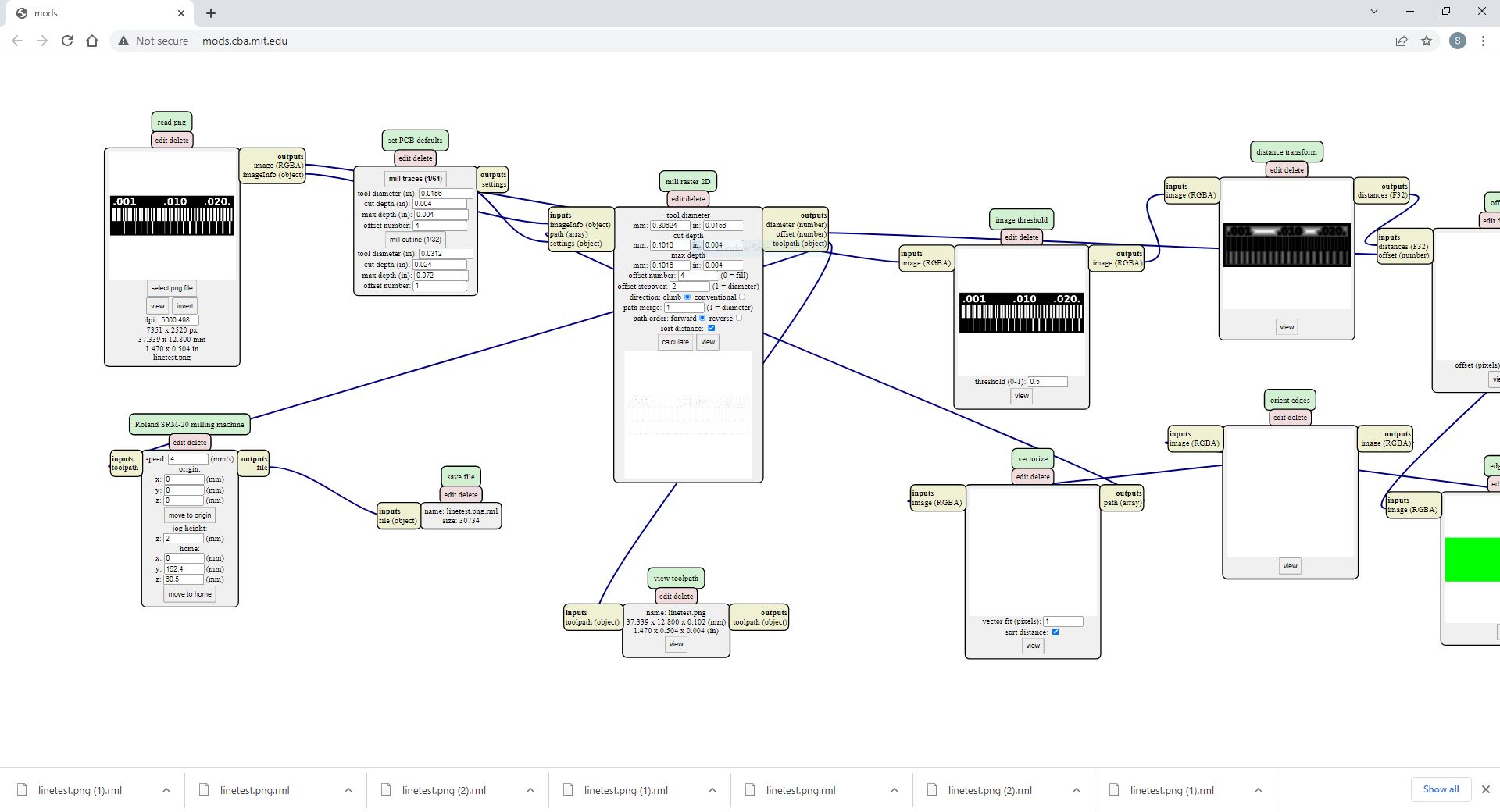
Toolpaths (also referred to as “CAM”, Computer Aided Manufacturing) was created using the Mod’s software. http://mods.cba.mit.edu
Notes on Mods
-
When using the Mods software, the part zero is the bottom left corner of the part.
-
Pay attention to the DPI of the PNG file when using the Mods PNG CAM software. Make sure the dimensions of the board are close to what you would expect the size of the board to be.
-
Sometimes the Mods software will stop responding. In these cases, you’ll have to reload and rebuild your Mods system.
-
Change your X, Y, and Z origins to 0mm.
-
Change the number of stepovers (Mods calls this “offset number.” The radial depth of cut is referred too as the “offset stepover.” This is given as a ratio to the tool diameter. Who the hell designed this?
-
Mods software uses non-traditional machining jargon. Recommend software is changed to become more inline with generally accepted machining practices.
Image of the Mods software in use for creating the traces of the board.
Tips and Tricks when operating the mill:
-
The jogging movement is controlled by Vpanel, and the options for the amount when pushing the jog keys is “continue” (not continuous, continue.) “100x” (which moves 1mm, not 100 microns as one might expect.), 10x and 1x. Maybe because this has been set for inches, but odd considering it’s a Japanese company.
-
As always when creating your part to be machined, create a system to “cut air,” ie, the tool is kept above the part, to make sure everything appears correct before committing to the part.
-
Be careful with the “continuous” jogging in Z. It wants to crash into the stock. Slow it down.
-
Use the Roland Japanese double sided tape. It is better at holding the FR1 board than the Scotch Brand double sided tape we also have in the soldering lab.
-
Remember to keep the lid closed, or the machine will not respond to commands.
-
Make sure that in the Vpanel, in the settings panel, it is set to millimeters.
-
When touching off the tool and setting offsets, allow the tool to drop slightly from the tool collet. You may also want to put gentle pressure on the pcb material, to allow for a slightly lower tool offset.
-
Important – Do not put the tool too deep in the collet. If you do this, the SRM 20 has an odd behavior, where when it reaches its negative Z limit, it will reverse to its positive Z position, and continue to mill the part in air. The tool needs to be approximately, at least 10 mm below the collet. This was an annoying issue. I looked through the RML code, and it seemed fine, and I’m used to receiving errors from a machine tool, not just seemingly random behavior. (Thanks Nick Nalley.)
-
Make sure to set both your X/Y origins as well as your Z origin.
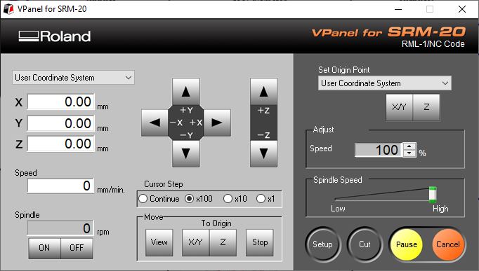
When you’re ready to cut, click the “Cut” button in Vpanel. The below window pops up.

Click “Add” to select the file you wish to cut. Then click “Output.” IMPORTANT: As soon as “Output” is clicked, the machine will start the spindle and start cutting.
Operation 1: Cutting the traces
The following are the settings we used with Mods and the Roland SRM 20 to cut out the traces of the board.
This is the PNG for the test piece.

| Operation 1 | Cutting Traces |
|---|---|
| Tool 1 | 1/64” (0.0156”) 2 Flute Square End Mill |
| Feed Rate | 240 mm/min |
| Spindle Speed | around 8300. |
| Style | Climb milling. |
| Rapid speed | 1800 mm/min |
| Total Depth of Cut | 0.004” (0.1mm) |
| Depth of Cut | 0.004” (0.1mm) |
| Number of Step downs | 1 |
| Number of Stepovers | 6 |
| Stepover amount | 0.0078” |
| Time of operation | 6 minutes. |
Operation 2: Board Cut from Material
PNG for the Board Cutout:

| Operation 2 | Cutting Board Contour |
|---|---|
| Tool 2 | 1/32” (0.0312”) 2 Flute Square End Mill |
| Feed Rate | 240 mm/min |
| Spindle Speed | around 8300. |
| Style | Climb milling. |
| Rapid speed | 1800 mm/min |
| Total Depth of Cut | 0.072” (1.83mm) |
| Depth of Cut | 0.024” (0.6mm) |
| Number of Step downs | 4 |
| Number of Stepovers | NA |
| Stepover amount | NA |
| Time of operation | 2 minutes. |
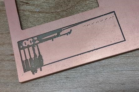
Results
This is where I learned that the double sided tape that shipped with the Roland SRM-20 and a Japanese brand that I can’t read is much better than the double sided Scotch tape we had around. I also believe that the tool was getting dull, and between the less sticky tape and the dull tool, the material was pulled right off of the spoil board. Here is what was left. If the tool wasn’t dull before, it was now.
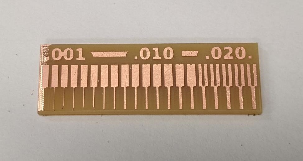
Second attempt:
Quick Look
The parts were examined quickly under a digital microscope.
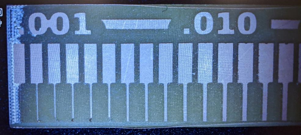
There was a part on the left side of the test piece that was not completely milled. We believe this was due to the piece not being perfectly flat. This did make it difficult to measure the smallest 0.001” line, however, it was still a useful test piece.
Optical Comparator
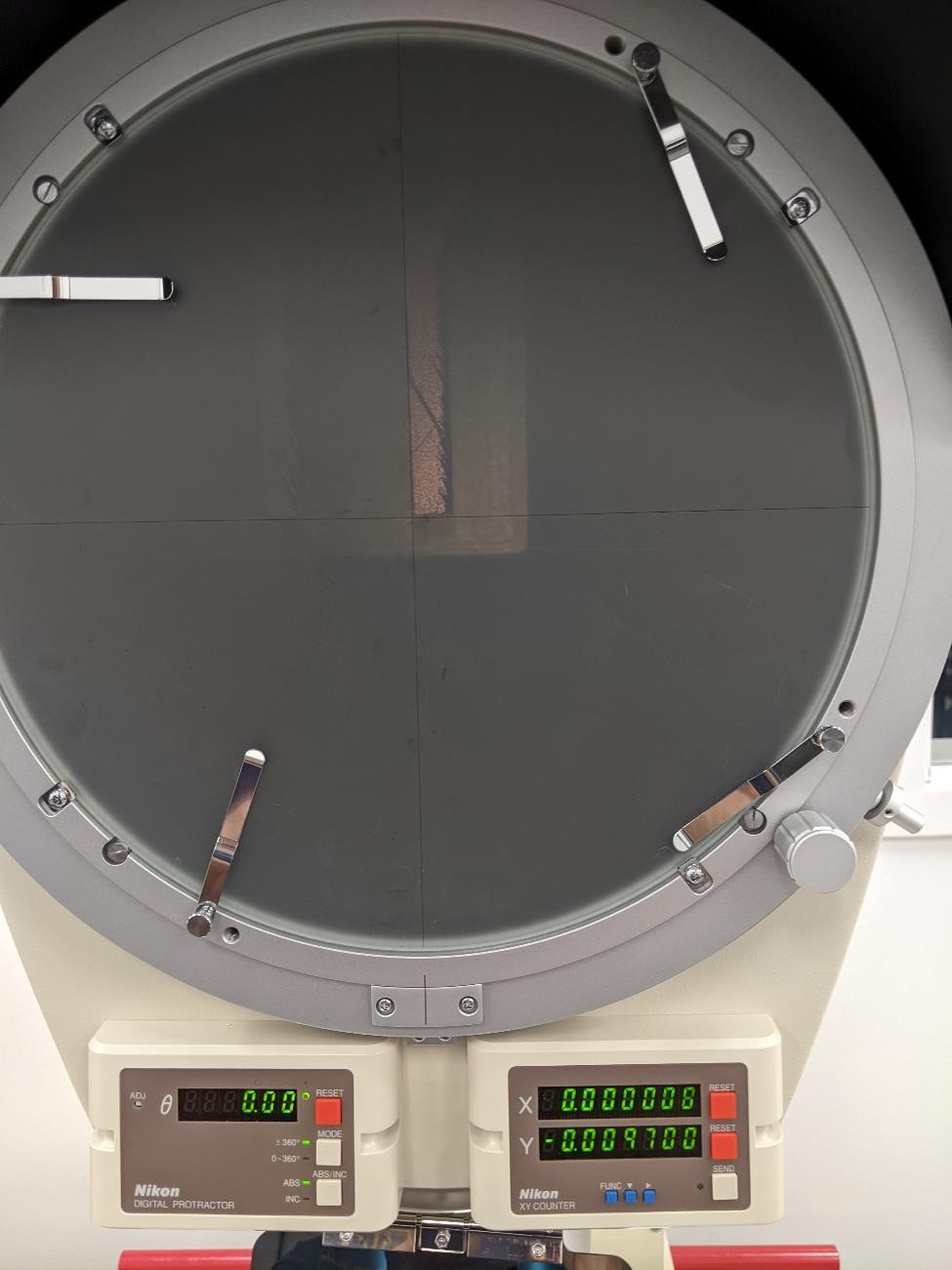
The test pieces were examined using a Nikon optical comparator with a top lit setup and DRO (Digital Read Out).
The optical comparator is capable of measuring parts to an accuracy of 0.0001” of an inch.
In this case, due to the top lit case, lighting at high magnification was difficult to achieve, and thus a higher accuracy was not achieveable with confidence. We examined the pieces by setting a zero on one side of the “slivers” and then measuring to the other side. In most cases, even given the constraints of the optical comparator, parts measured within a 0.0001” 0.0004” of the programmed tool path. And again, these were sub-optimal conditions to measure the test pieces.
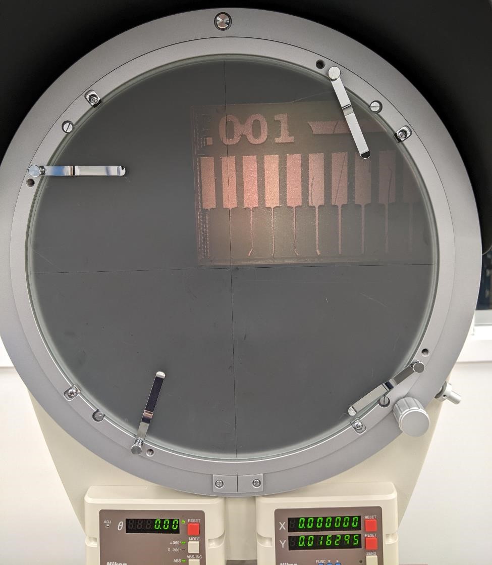
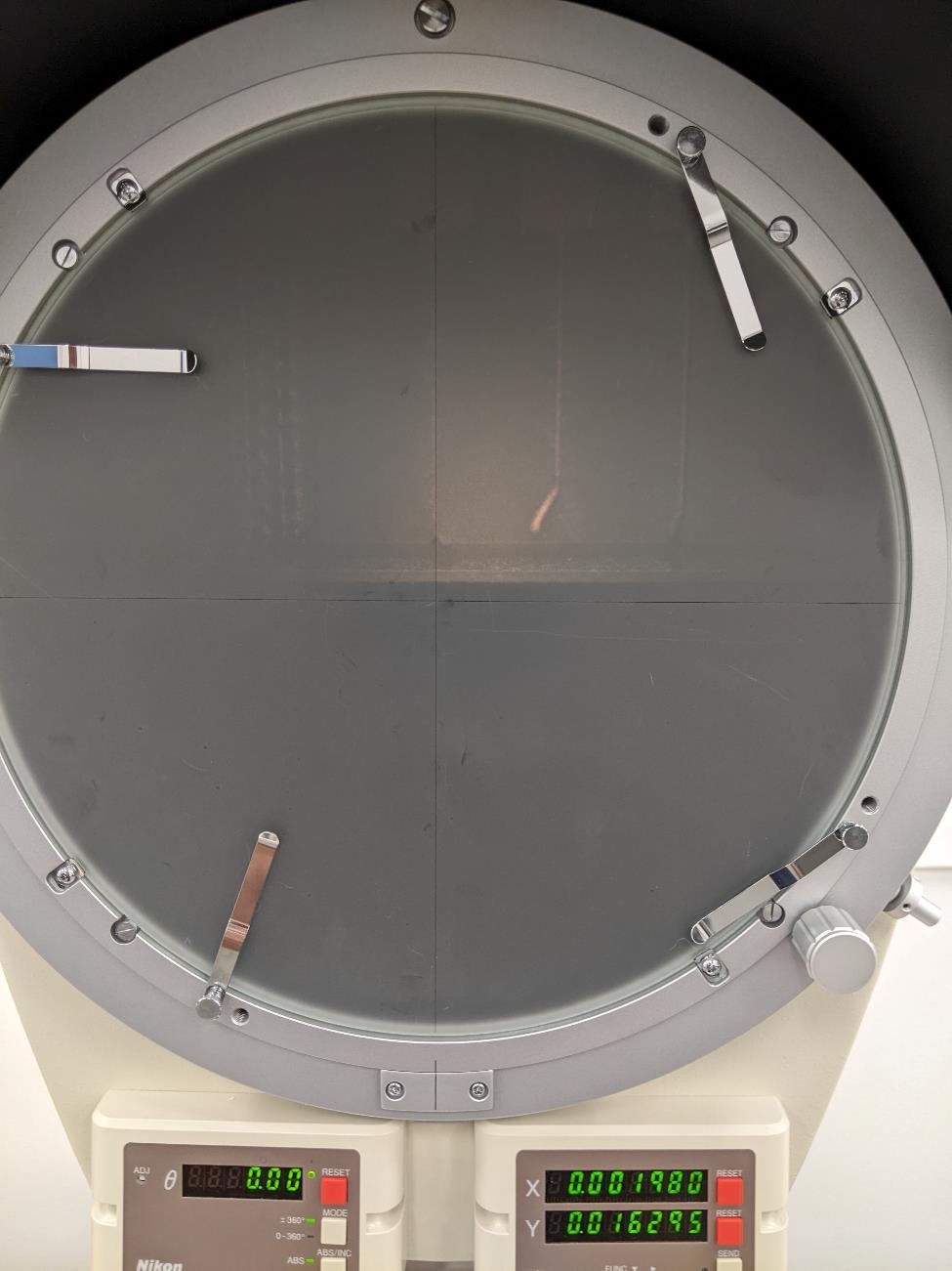
0.002” Line Width
Here is a measurement of the 2nd finger in the test piece. This piece is supposed to be 0.002” wide. The first image shows setting the DRO to 0.
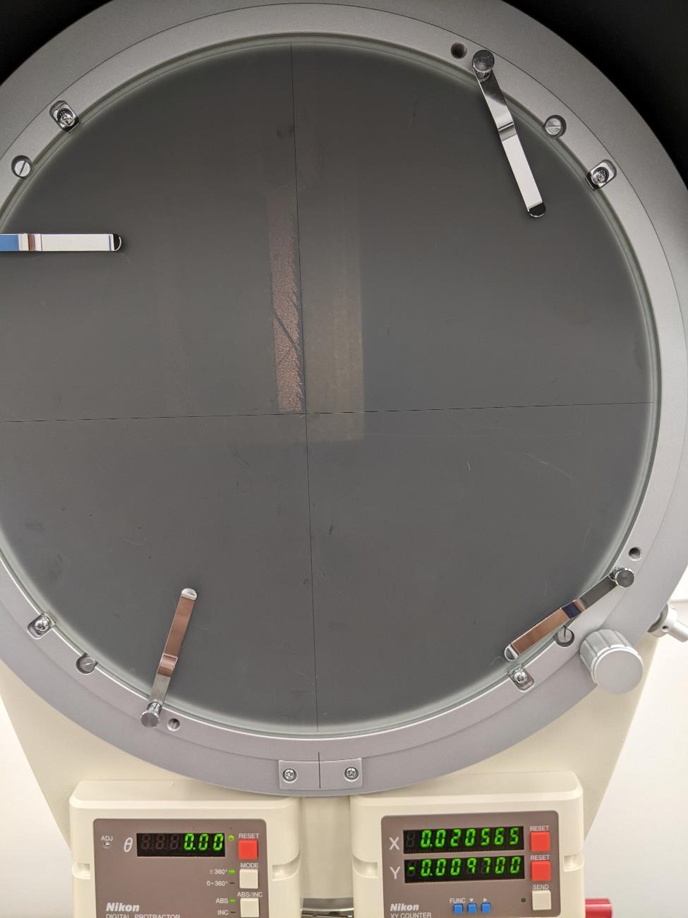
The second image has moved the measuring crosshair to the other side of the line, and reads a measurement of 0.0019”. 0.0001” off the actual programmed size. This variation may be due to poor lighting and user error. Also note the difficulty seeing the test piece due to front lit setup.
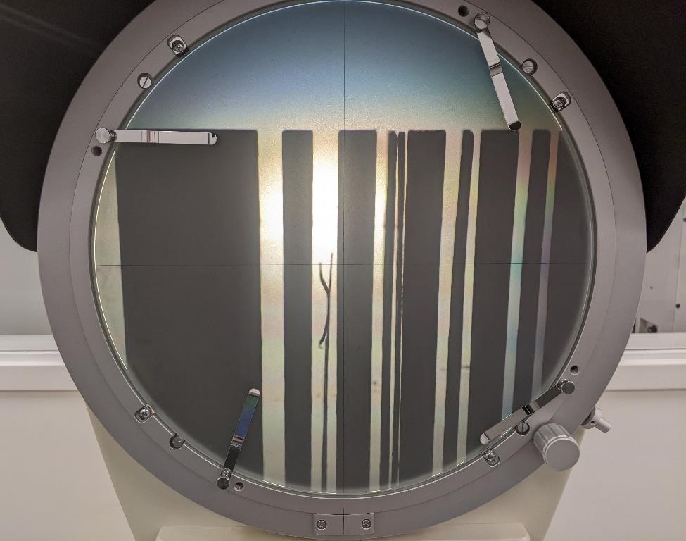
0.020” Line Width
The above test was done again with the widest line of 0.020”. The results were equally as impressive when taking into account the difficulty of measuring the sample pieces. In this case, the error was larger. The reading was 0.0205”, meaning the error was 0.0005”.
Tool Radius
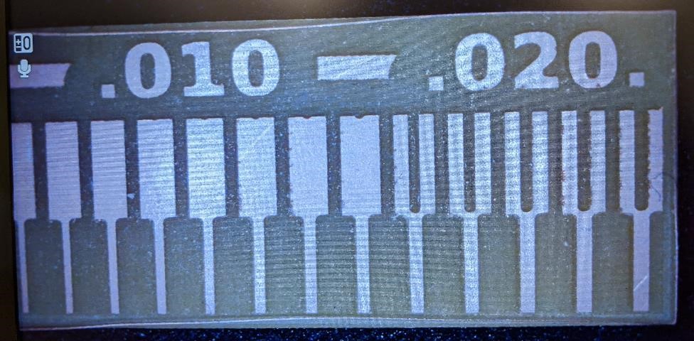
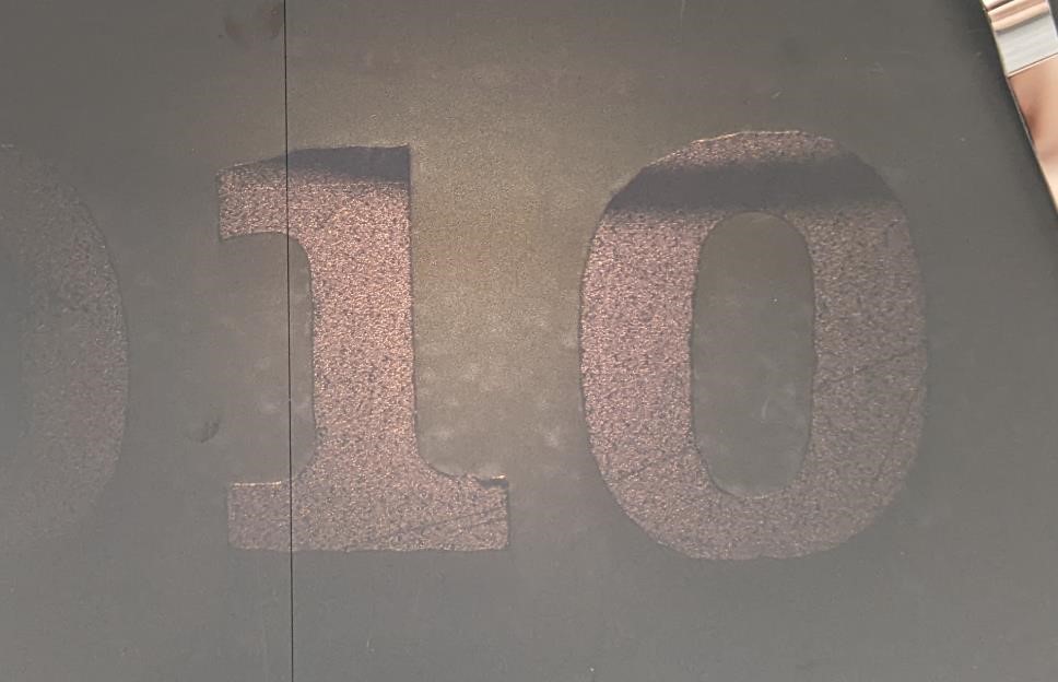
Finally, we looked at the numbers engraved on the piece.
In the below image, you can see the “10” from the “.010” at the top of the part. Where the line that makes up the number one, connects to the main line of the “1” you can see the tool radius. However, this is a very small radius (obviously, it’s a 0.0156” tool, with a radius of half of that.) and the radius is hardly noticeable.
Also note the shadow on the image, it’s from a stray piece of copper that had been along the sides of the engraving and had peeled away. It wasn’t noticeable until the sample was place in the optical comparator. This peeled copper was probably only about 0.002” wide.
Extra Credit
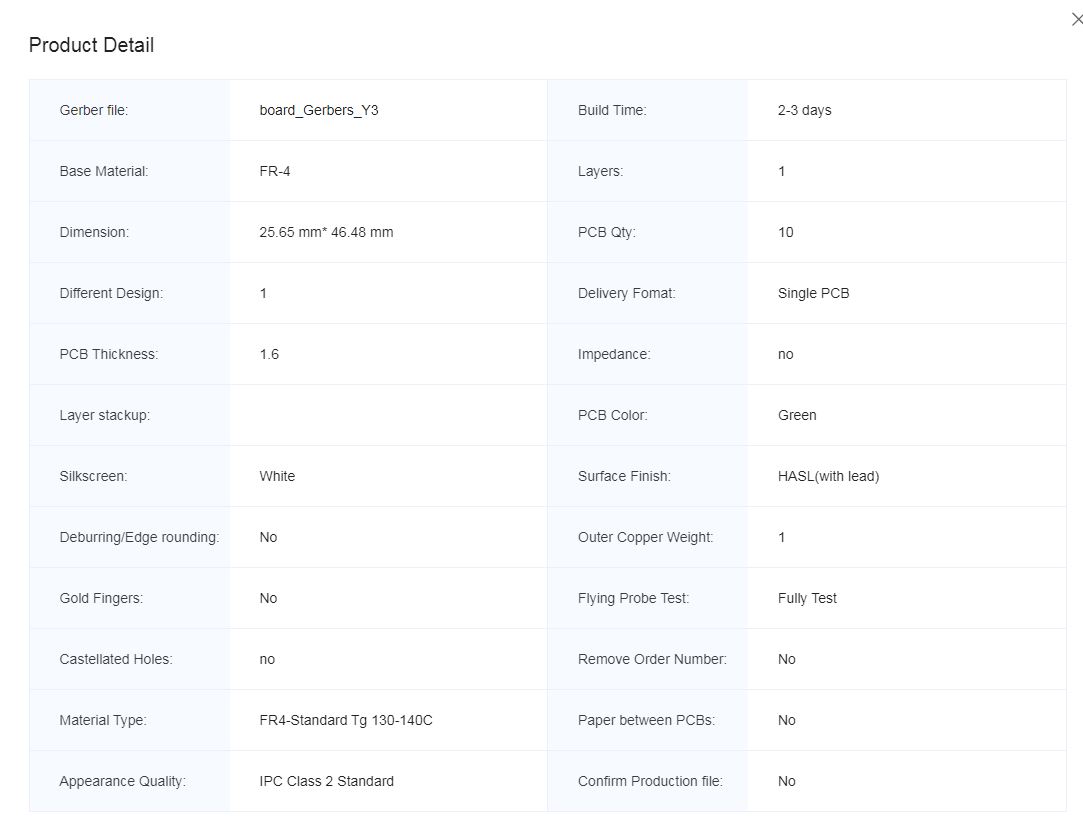
We took the Gerber Board files and sent them to JLCPCB to have them made for us. You can find the gerber files for this in Adam Harris’ FabAcademy Gitlab page: https://gitlab.fabcloud.org/acharris/fab11c
It should take about 2 weeks to receive the completed boards (because Garrett didn’t want to pay for faster shipping.)
Update: They’ve been shipped, just waiting for them to arrive.
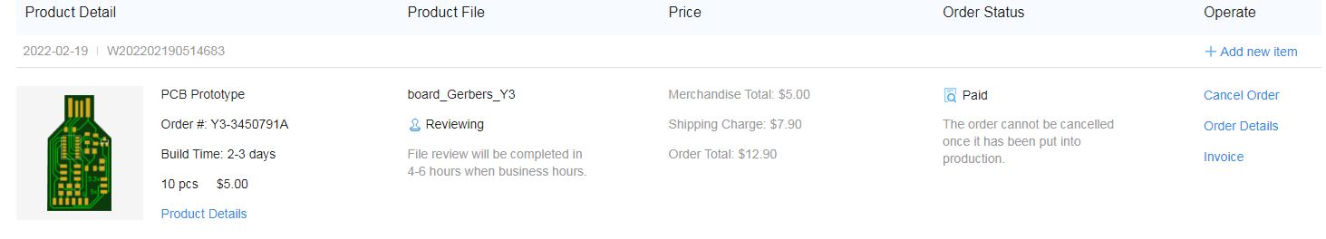
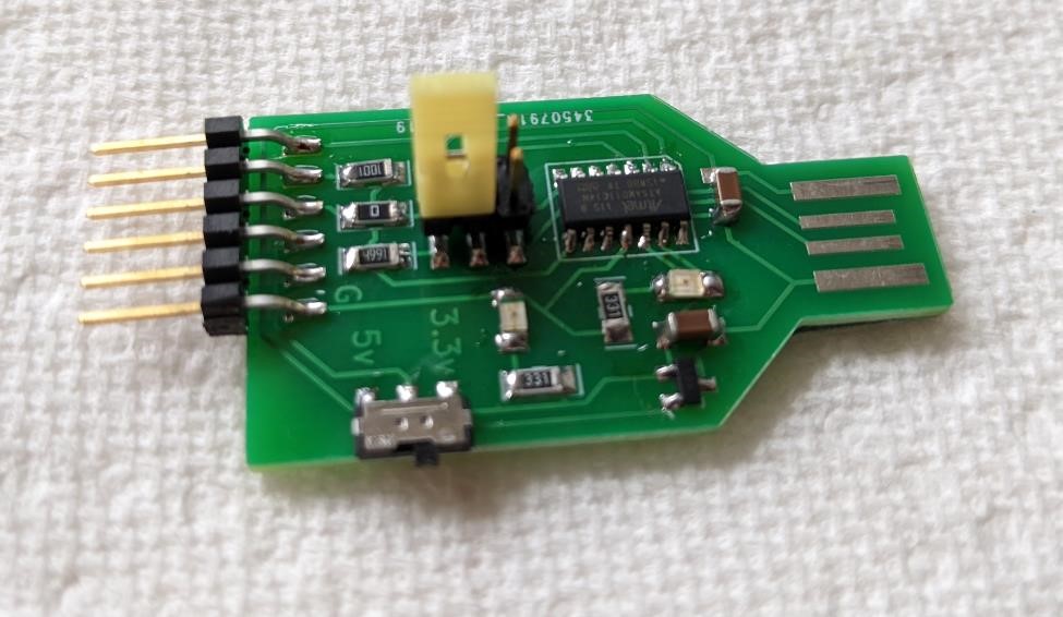
UPDATE 3/3/22: They’ve arrived. They look nice. Here’s one ready to program.