4. Group Project - Cutting
2-9-22
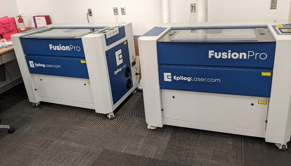
We were using the CPCC Fab Lab’s new Epilog Fusion Pro 32 laser engravers. They are simple to use, and have automatic focusing, as well as an overhead camera to allow easy work coordinate assignment and set up. Many of the setup steps for producing a file ready to cut are similar to vinyl cutting, and with the exception of color management, the settings are very similar.
Remember to change your line stroke width to 0.1 pt, as well as the color to red (255,0,0) for cutting. But as this is a laser engraver, you can also engrave with it. If you wish to engrave vectors, you can change the color to green (0,255.0) to engrave. For other engraving tasks, you should probably change the image to grayscale.
Set Up
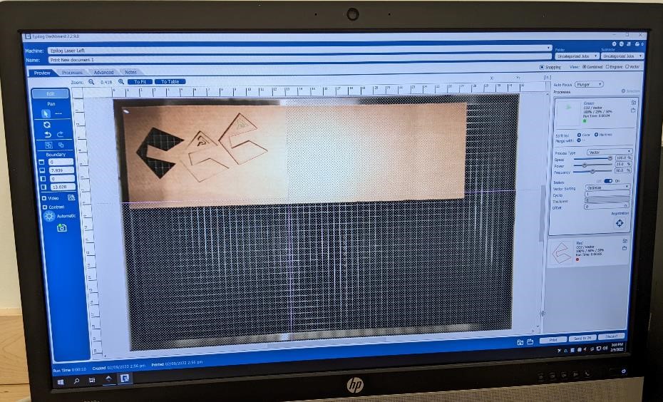
This is the Epilog Job Management software, and you can see a camera’s view of the test pieces.
When setting up the Epilog laser cutter:
- Make sure that you have your document properties set in the correct units.
- Make sure that your document area is similar to the area of your project (easy to forget to do this.)
- Set up the colors and line width for your print. Red for Cut, Green and grayscale for engrave.
Procedures for using the Laser Cutters
First, make sure to know where the water spray bottles, fire blankets, and fire extinguisher are located.
Turn on the Exhaust fan (the switch for this is across the room, by the cubbies, against the wall under a cover and labelled “EX FAN 5.”
Make sure the baffles on the exhaust of the laser engraver itself is open (these are the black “doors” sitting on the silver tubing coming from the back of the laser engraver itself.) To open them, simply pull up. It helps to close the one of the laser engraver that is not being used.
Log on to a computer. The two computers closest to the laser cutters are each individually connected to only 1 of the lasers. The laser engravers are called “Left” and “Right” (with this obviously being their location.) The computer furthest is connected to the left laser, the one closest (and is actually next to the left laser) is connected to the “Right” laser.
Whichever computer you long on, turn on the corresponding laser engraver by inserting the key and turning it to the “I” symbol (for On.) You will need to get the key from Adam Harris or Michael Long.
Choose your file that you wish to print. You should be able to print from a number of applications, such as Inkscape, Corel Draw, and Autocad.
You will want to make sure that you have thin lines, the correct color lines (red for cutting, green for engraving) and that your document size is set appropriately.
Print your file, and choose the “Epilog Engraver” from the print window, and click okay.
If this is the first time using the laser, you may need to first set up the laser with the Epilog Manager.
The laser is a Epilog Pro 32 (under “Other”) It has a 120 Watt CO2 laser and No Fiber Laser
The IP Addresses for the lasers are: Left : 10.35.160.122 Right: 10.35.160.121
Name the Laser according to the “Right”/”Left” dichotomy.
You may then need to close this window, and re-print your file again.
This time, you should be able to have the Epilog Dashboard laser manager window appear and you should be able to see an image of the laser table through the camera and your file.
Place the material you will be cutting/engraving in the laser engraver and close the door.
Center your file in the Epilog Dashboard, by clicking and dragging. Make sure that if you move it drastically, to also change the dashed-red/pink lines. This is the work area of the laser. If you forget to move these, the laser will not engrave/cut the parts that are outside of this area.
Make sure to set the “Auto Focus” to Plunger
And change the Speed and Power based on the material you are cutting. See the Chart and consult the lab assistant or your instructor for more details.
When you have these set, click “Print.”
Move to the laser.
You can double check your work area, by clicking the tiny “laser” button (center, bottom) of the laser engravers LCD screen. This turns on a red laser (this isn’t the cutting laser, don’t worry.)
You can then press the squarish symbol button to the right (by two places) of the red laser button. This will move the laser head around and show you the work area of your part. When you’re satisfied it looks correct. Press the same button again to turn the movement off. You can also turn the red laser off.
If you’re ready to go, double check your exhaust fan is working, you have some water/fire extinguishers nearby and press the “Play” button on the laser engraver. If at any point, you think something is wrong. Press the same “Play/Pause” button to pause the laser.
When you are finished using the Laser Cutter, please turn it off, and very carefully remove the cut tray (the tray your part rests on with all the thin metal cubes) and clean out any debris left from your cuts. Small pieces of cardboard and wood are fire hazards if they accumulate.
Turn the Exhaust Fan off.
Log off the computer.
Testing
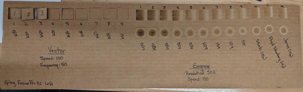
This is one of the test articles we created for testing and classifying the laser’s abilities. We made “comb” tests, which would take different cuts for different thicknesses. As an experiment, I tried one that was the opposite, to see how small we could create “fingers” without blowing them off of the main body.

I want to point out that during this process of designing these, the Inkscape tool menu for “Align and Distribute” comes in quite handy. It allowed me to take the boxes and quickly align them so that they were even with one another, as well as to evenly distribute them across the cutting area. You can find it under the “Object” menu, or pressing “Shift+Ctrl+A” on Windows.

When you’ve done the above and you’re ready to print, you can send your file to “print,” select the laser engraver and click “print.”
We started with the manufacturers recommended speeds and feeds, which was 100% speed, 50% power and 50% freq; and that for engraving, 100% speed, 25% power and 50% freq. From a few quick cuts, it seemed this was close to the correct parameters (at least useable results,) Garrett designed some images for creating test pieces to better characterize the laser cutter.
The first test consisted of 3 parts.
- The first section was finding a good power/speed for cutting without too much burnout or “waisting.” We cut 1” squares out of the stock.
- The second and third part were measuring the engraving power, and was a qualitative measurement in order to find the right settings to get high quality engraving results. We created two 1 inch squares, with two different gradient patterns.
The test was run multiple times, changing one of the key variables (speed, power, frequency or resolution) for each part. However, while this test is somewhat scientific, there were sometimes multiple changes made at the same time. This was in part because of time constraints, as well as the fact that it becomes obvious when one of the variables is producing sub-optimal results, and thus it makes sense to test in areas that are more likely to be useable.
Cutting
For our first cutting tests, we used 1/8” corrugated cardboard and “1/8” birch plywood (actually 0.130” or 3.3mm). The cardboard was kindly supplied to us from Charlotte Latin School.
We cut 1” squares. The point was to find a setting that would allow for high quality cuts, without burning the cardboard, and getting a nice cut surface, while getting complete cut through.
Laser Cut - 1/8” corrugated cardboard
This test decreased power, while leaving speed and frequency untouched. We found that good setting was around 35% to 25% power to get a through cut. Anythign less than 25% did not adqequitely cut the part.
| Cut Sample | Speed (%) | Power (%) | Frequency(%) | Notes (%) |
|---|---|---|---|---|
| 1 | 100 | 50 | 50 | Hot |
| 2 | 100 | 40 | 50 | |
| 3 | 100 | 45 | 50 | |
| 4 | 100 | 40 | 50 | Good Cut |
| 5 | 100 | 35 | 50 | |
| 6 | 100 | 30 | 50 | |
| 7 | 100 | 25 | 50 | |
| 8 | 100 | 20 | 50 | No Cut |
| 9 | 100 | 15 | 50 | No Cut |
We made a few test cuts without using the auto-focus feature, however, in terms of cutting, we noticed no obvious difference in the cuts.
Laser Cut - 0.130” birch plywood
This test changed the speed, rather than the power, as the power starts at 100%.
| Cut Sample | Speed (%) | Power (%) | Frequency (%) | Notes |
|---|---|---|---|---|
| 1 | 12 | 100 | 10 | |
| 2 | 15 | 100 | 10 | |
| 3 | 17 | 100 | 10 | |
| 4 | 19 | 100 | 10 | |
| 5 | 21 | 100 | 10 | |
| 6 | 23 | 100 | 10 | |
| 7 | 25 | 100 | 10 | |
| 8 | 30 | 100 | 10 | No Cut |
| 9 | 35 | 100 | 10 | No Cut |
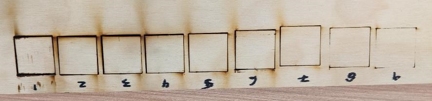
This images shows the back of the plywood test, and shows the lack of cut through on the last couple of pieces. Note that compared to the front, which looks very similiar between cuts; on the back is where you can see the difference in cutting speed/power.
Kerf Measurement
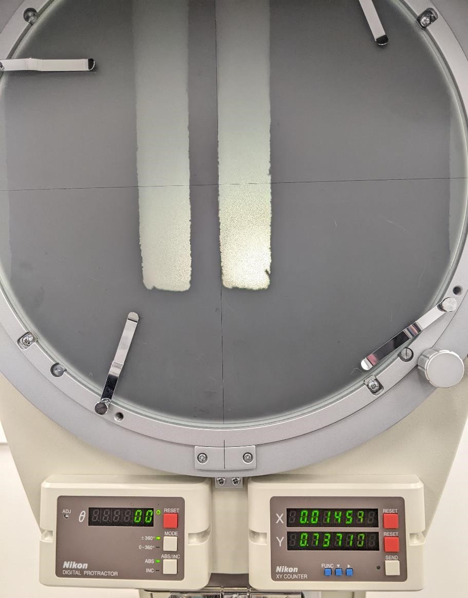
There were a couple of things that we tried. We made test cuts out of cardboard and measured them with an optical comparator.
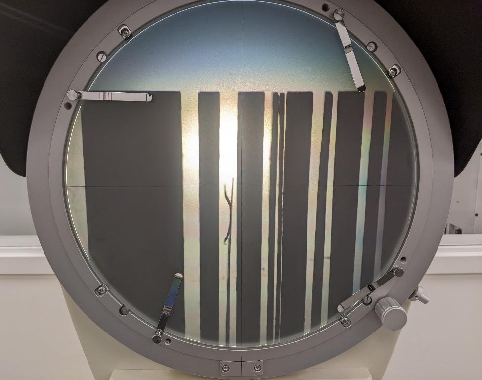
We used the squares created for the cutting test, as well as purpose made cutouts to help measure kerf, as well as to see how the laser cutter handled fine lines. The keft cutout parts were rectangles cut out of the part, as well as having fingers left in the part.
The sizes of these fingers were:
| Width (inches) |
|---|
| 0.010” |
| 0.020” |
| 0.030” |
| 0.040” |
| 0.050” |
| 0.075” |
| 0.100” |
| 0.150” |
| 0.200” |
| 0.200” |
| 0.250” |
| 0.3125” |
| 0.375” |
| 0.500” |
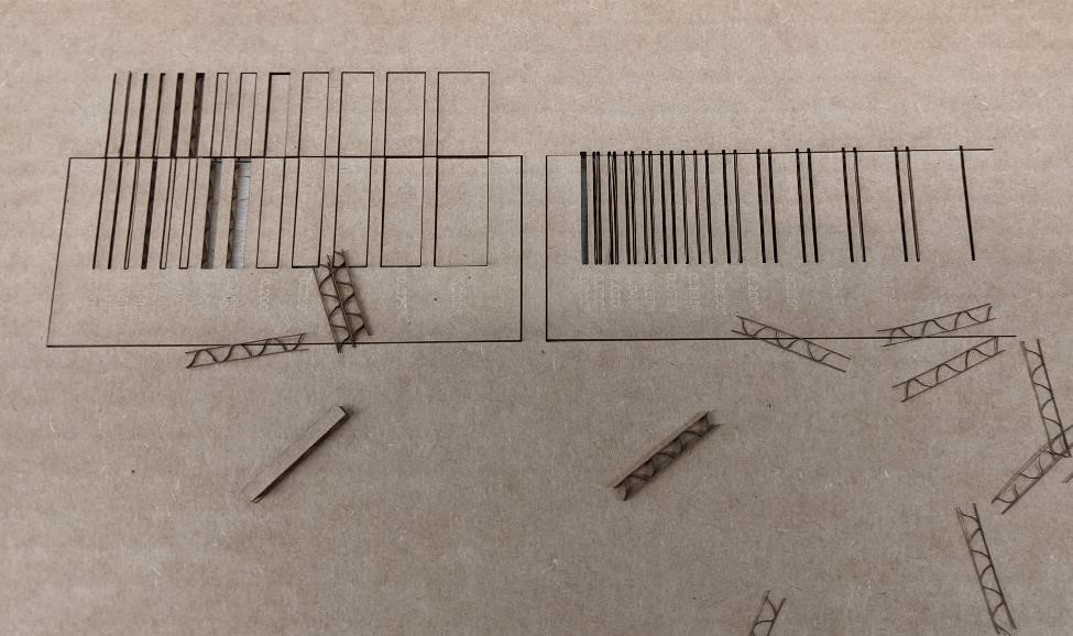
The above is the part used for these tests.
Here you can see that a piece of cardboard that was supposed to be 0.010” (0.254mm) was completely obliterated by the laser. The same was true for 0.020” (0.5mm). At 0.030” (0.75mm) the “finger” was not cut out by the laser.
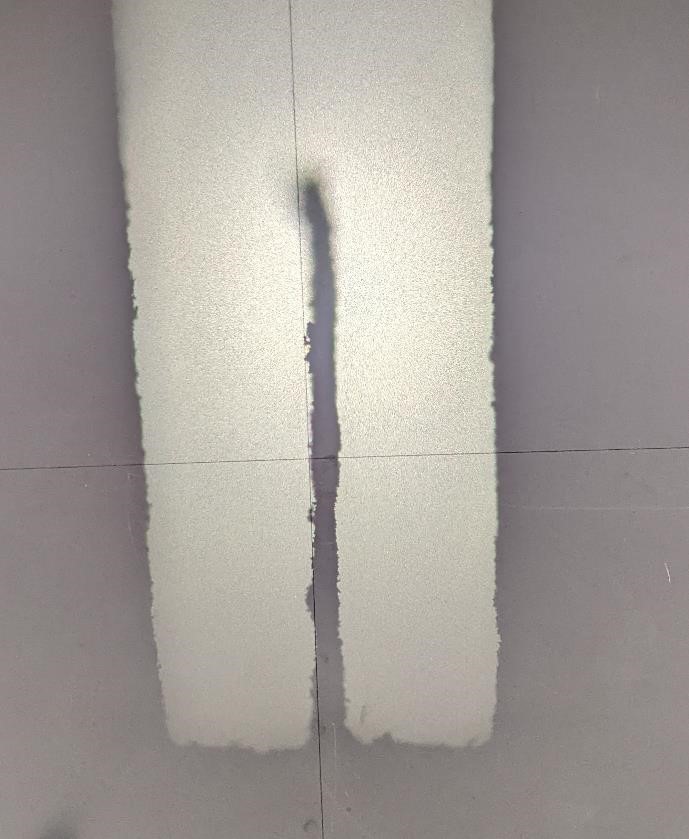
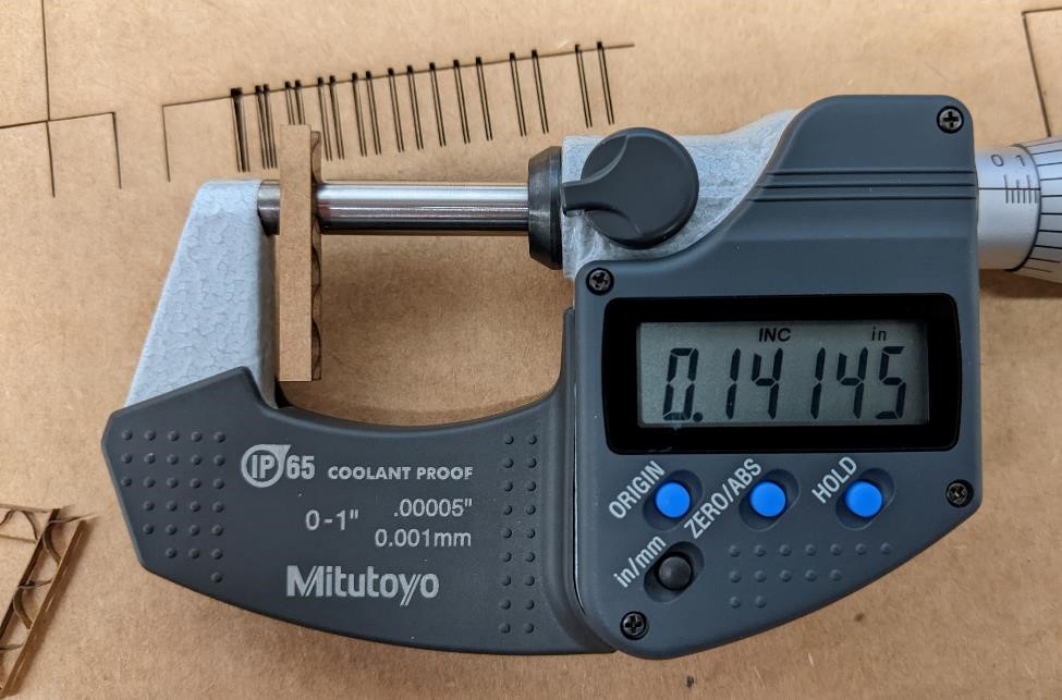
The next image shows the thickness of a nominally 0.020” (0.508mm) finger, but it measured as 0.0145” (0.368mm) on the optical comparator.
The gaps between the fingers was 0.020” (0.508mm). In retrospect this may have been too tight, especially given the kerf, but it was suitable for the test.
Measured Kerf… drumroll please....
After looking at these parts under the optical comparator, we determined that the kerf was approximately (and averaged) 0.008” (0.2mm). Ta Da!
However the kerf is not like a saw or mill, in that it would typically be on the outside of the line to be cut, but rather with the laser cut, it is cutting on the line, and as such is equally distributed on each side. The Kerf (as mentioned) above, also has a waist, making it a dependent on the type and size of material.
Fitment Tests
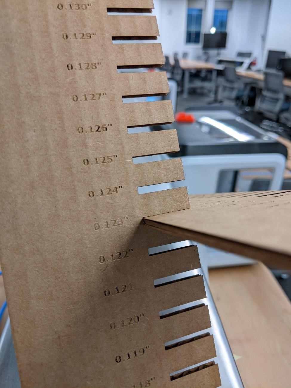
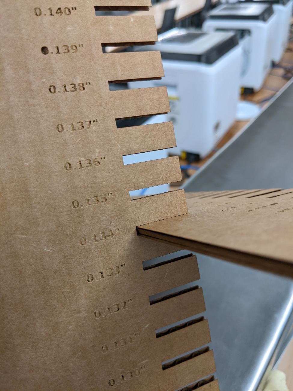
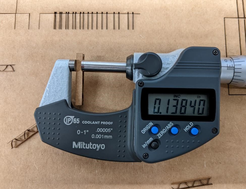
We wanted to see what the correct size to print to have a good solid joint was. We created a test pattern that increased by 0.001” for each cut. This was the nominal size and did not take into account the kerf.
We found that the results for a nominal 1/8” cardboard were a very tight fit at 0.123” nominal cut. Anything below this would have required permanent deformation of the cardboard. And there was a nice easy fit at 0.134”, which would work well for most simple construction parts designed for puzzles or pieces that would be put together and taken apart often.
“Taper” of parts
We noticed, and this can be seen up above, that there is a “taper” or “waist” to the part after being cut by the laser. In one case, on the 1/8” cardboard, this taper was measured to about 0.003” (0.076mm) over the depth of 1/8” (3.175mm).
Engraving
This is more of a qualitative and subjective test. However, it is easy to see when things go wrong. Burn through and charring are quick to see, and would ruin an engraved piece.
It was easy to burn through the cardboard with more powerful settings. But it was also interesting to note that burn through was affected by the underlying corrugation pattern.
Engraving Cardboard
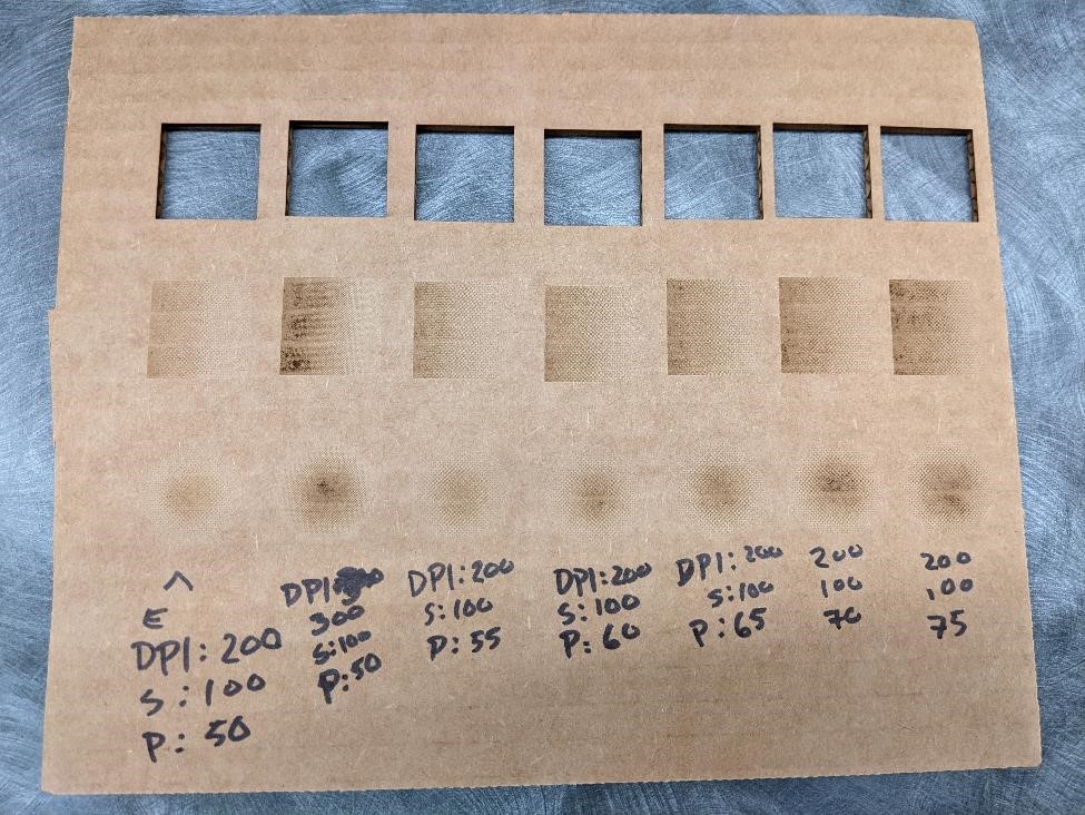
As stated before, we started with two 1” squares, each with a different gradient pattern. From there, we changed the power in increments of five, and kept the resolution and speed the same.
In this case, the first few tests were too strong, and the darkest portions of the gradient burned through the top layer of cardboard. Engraving required much lower power than vector overall, as 15 power seemed to give the best results in cardboard.
| Cut Sample | Speed (%) | Resolution (DPI) | Power (%) | Frequency (%) |
|---|---|---|---|---|
| 1 | 12 | 200 | 50 | 12 |
| 2 | 15 | 200 | 55 | 12 |
| 3 | 17 | 200 | 60 | 12 |
| 4 | 19 | 300 | 45 | 12 |
| 5 | 21 | 300 | 40 | 12 |
| 6 | 23 | 300 | 35 | 12 |
| 7 | 25 | 300 | 35 | 12 |
| 8 | 30 | 300 | 35 | 15 |
| 9 | 35 | 300 | 35 | 17 |
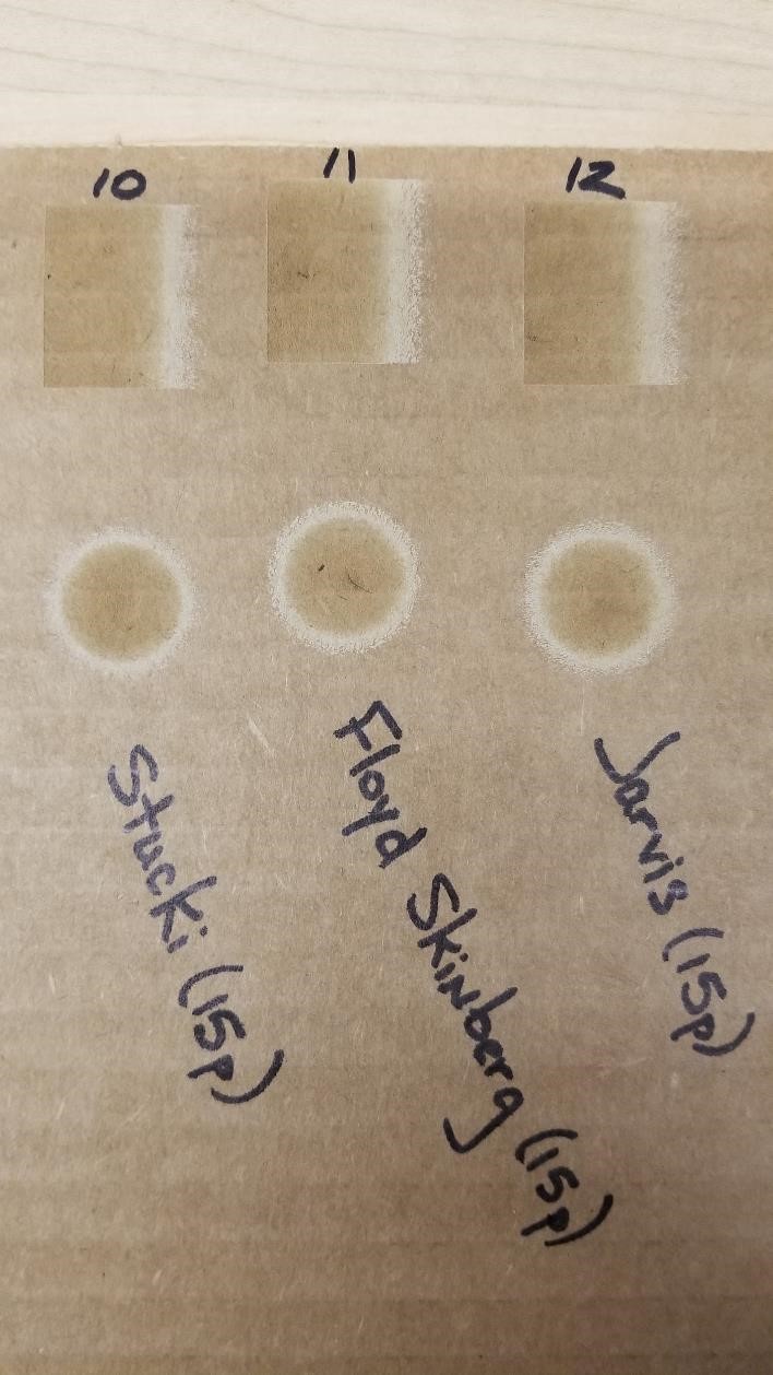
We also tested a few different dithering modes, using 15 power, which gave very different results against the standard dithering. On all three styles tested, the center darker circle was much more defined, and the remaining gradient became a thinner, light ring around it. The square showed the same kind of definition, with the darker portion remaining consistent across roughly 75% of the space, and the remaining section tapering off from a light much lighter band. It was also much easier to see the pixel patterns for each style. Also, the Floyd Skinberg option seemed to singe the center just slightly, but more tests would be necessary to see if this is a consistent problem.
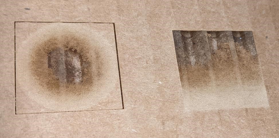
Here’s an up close image of an engraving that used a more powerful setting of 50% power. You can see the burn through of the areas that are completely black (the center and top respectively). What’s interesting is that you can also see the dithering effect and the halftone pattern in these images. (And for more about dithering, see: https://en.wikipedia.org/wiki/Dither
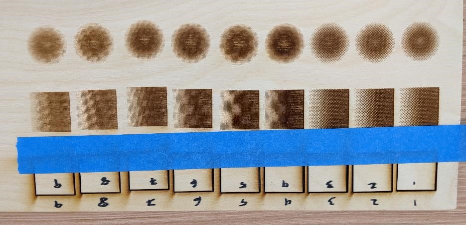
Like we said before, engraving is subjective to a degree, but it’s clear where the centers or darkest sections have burned or singed. 25 and 20 power were both slightly singed in the very center of the circles, but 15 is where there were no visible singed spots in the middle. After that point, 10 and 5 power tapered off quite a bit, and the last circle is visibly smaller than the others.
The squares followed the same pattern for the most part, but 20 power also looked like a viable option, though the top layer of cardboard may be a bit thin in places. From here, the same fading occurred as the circles, with the least amount of power engraving the most narrow square, or at this point, rectangle. Square number 9 also had the thinnest dark band, and faded quickly into the lightest color.
Overall in cardboard, test number 7 gave the best results for color contrast, for dark and light colors without losing the overall size of the squares to fade.
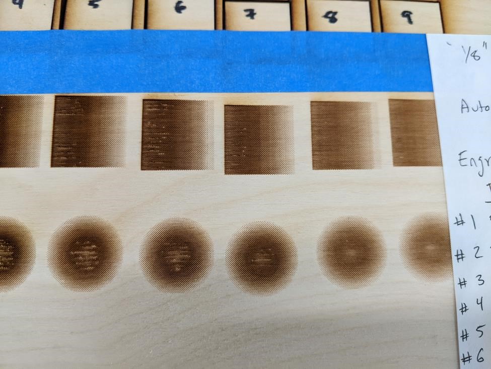
Engraving Birch Plywood
Next, we switched out the cardboard for the plywood sheet and repeated the tests, but with slight variation this time. Immediately, it was clear that this material was very different. The dots or pixels that made up the images were much more defined, even in the tests that singed. It also became clear that because of this definition, we could play around with the resolution and see exactly how that changed the appearance and performance of the engraving.
| Cut Sample | speed (%) | Resolution (DPI) | Power (%) | Frequency (%) |
|---|---|---|---|---|
| 1 | 12 | 200 | 50 | 12 |
| 2 | 15 | 200 | 55 | 12 |
| 3 | 17 | 200 | 60 | 12 |
| 4 | 19 | 300 | 45 | 12 |
| 5 | 21 | 300 | 40 | 12 |
| 6 | 23 | 300 | 35 | 12 |
| 7 | 25 | 300 | 35 | 12 |
| 8 | 30 | 300 | 35 | 15 |
| 9 | 35 | 300 | 35 | 17 |
For the first three tests, we started the resolution at 200 and instead increased the power. This would have burned the cardboard immediately, but the wood held up very well, and even at the highest setting we tested, the engraving looked pretty good. It’s darker than the others, but not to the point where the overall gradient is lost.
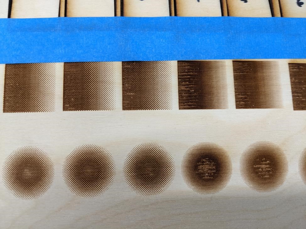
Since we had tried different power levels, we moved on to testing a different resolution at those same power levels. For the remaining tests, we set the resolution to 300, and started with the recommended power of 50. Test 4 was much darker than Test 3, which made sense. A higher resolution means a higher concentration of pixels, which means there is more heat, thus a darker image. From here, we decreased the power in increments of 5. Unfortunately, this didn’t seem to help the singing issue in the center of the circles and the leading edges of the squares. Test 7 gave the best results, but didn’t eliminate the problem entirely.
For the last two tests, we decided to change the speed. When we tested the cutting, speed played a big part in the quality of the cut edge. Faster speeds meant the laser had less time to add heat to one spot, thus reducing the chance of burning and discoloration. For Test 8, we increased the speed slightly from 12 to 15, and there was a clear improvement in the discoloration, but the singed center remained. We increased the speed again, this time to 17, and had our best result. The gradient seems much smoother, the pixels are well defined, and the overall size of the squares, though slightly smaller, remained fairly consistent.
Overall, with engraving, very minute changes and adjustments to the variables are able to make a big difference in the final appearance of the image. Simply changing the speed by two points made a very obvious difference. The same applies to increasing the resolution. Power seems to have a more gradual effect, but still plays an important role in the quality of the image.