4. Electronics production

Weekly Assignment Requirement
Group assignment:
- Characterize the design rules for your in-house PCB production process: document feeds, speeds, plunge rate, depth of cut (traces and outline) and tooling.
- Document your work (in a group or individually)
- Document your work to the group work page and reflect on your individual page what you learned
Individual assignment:
- Make an in-circuit programmer that includes a microcontroller by milling and stuffing the PCB, test it to verify that it works.
Have you answered these questions?
- Linked to the group assignment page
- Documented how you made (mill, stuff, solder) the board
- Documented that your board is functional
- Explained any problems and how you fixed them
- Included a ‘hero shot’ of your board
What I’ve done this week
Group assignment:
Individual assignment:
- Use CNC for cutting a circuit board
- Solder surface mount parts on a circuit
- Write programs on the D11C
- Write program on the FT230X
Use CNC for cutting a circuit board
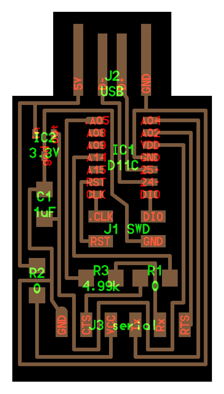
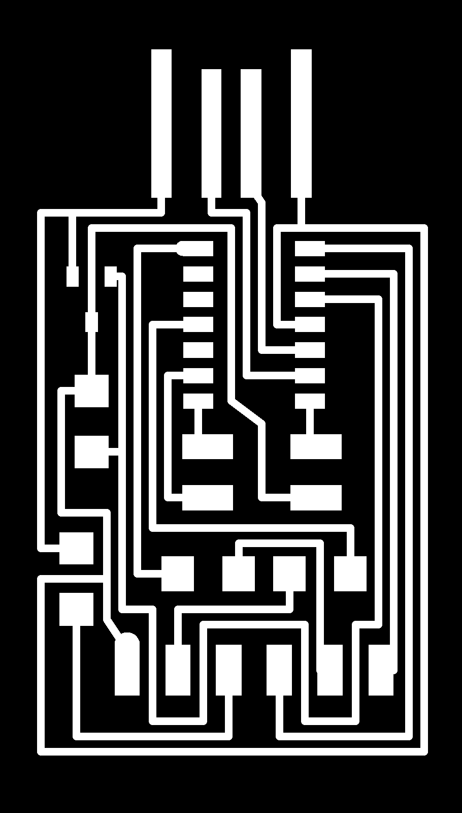
First, I cut hello.D11C.serial board based on the following image using milling machine.

Use mods for creating rml file
I converted the png file into rml format, which is data that can be processed by the milling machine.
As with the group work, I used mods.
The first step is to create the framework of the flow, and then enter the parameters.
Right-click on an empty area of the screen, you can see the following node.
Select “program” ⇒ select “open server program” ⇒ select “PCB png”

When you select “PCB png”, you can see the workflow as shown below.

Right-click on an empty space on the mods browser screen can bring up a new node.
modules ⇒ open server module => file save ⇒ Click on the output of the Roland SRM-20 milling machine and the inputs file of the newly created node and connect them with an edge.


Now that the framework of the flow is complete, I can start entering images and parameters.
Select “Select png file” and choose the png data you want to export.
For hello.D11C.serial.5V.1.1.traces.png, select 1/64.
For hello.D11C.serial.5V.1.1.interior.png, select 1/32.

Change to origin (0,0,0) => Calculate => rml file is exported automatically.

Selecting “caluculate” is open another page in browser, where you can see the following for each

It is also download rml file.
Cut PCB
As in the group work, I used SRM20 to process a circuit board.

Use a 1/64 drill for traces cutting and a 1/32 drill for outline cutting

Open the vpanel of SRM20 and configure the origin settings

When adjusting the origin of the z-axis, close the screw while pressing the drill against the surface of the base with a downward force by hand.

If you do not do this, the drill will move away from the surface a little when you close the screw, and you will not be able to process at the proper z-axis height that you have set.
Once the origin is set, the next step is to cut it.
When you select “Cut”, a screen to select a file will appear, select the target rml file and click “output” to start processing on the SRM20.

Done

When cutting is complete, remove the cut board from the SRM workbench and wash it with water. Then apply flux.

Solvent makes it easy to remove the double-sided tape from the cut substrate.
Flux is a soldering accelerator. Soldering does not work well if there are foreign substances or oxide films on the surface of the metal to be joined.
Applying flux will ensure optimal soldering.
Solder surface mount parts on a circuit
Before soldering, lay out the parts on a paper and write their names next to the parts.

The parts in the lab were limited, so I did my best to solder them

Write programs on the D11C
I followed Mr. Jun Kawahara’s (FabLab Kamakura) documentation to build this environment.
Download an edbg binary
Since I am using a mac, I selected “edbg-mac-r29”.
I’m using zsh, so I wrote the following in my .zshrc
export PATH=$HOME/(my directory)/edbg:$PATH
Restart a terminal
Then, try edbg -h command to see if the command works. If it works, it will return messages like this.
%  edbg -h
CMSIS-DAP SWD programmer. Built Feb 19 2022 11:10:16.

Usage: edbg [options]
Options:
  -h, --help                 print this help message and exit
  -b, --verbose              print verbose messages
  -x, --reset <duration>     assert the reset pin before any other operation (duration in ms)
  -e, --erase                perform a chip erase before programming
  -p, --program              program the chip
  -v, --verify               verify memory
  -k, --lock                 lock the chip (set security bit)
  -u, --unlock               unlock the chip (forces chip erase in most cases)
  -r, --read                 read the whole content of the chip flash
  -f, --file <file>          binary file to be programmed or verified; also read output file name
  -t, --target <name>        specify a target type (use '-t list' for a list of supported target types)
  -l, --list                 list all available debuggers
  -s, --serial <number>      use a debugger with a specified serial number or index in the list
  -c, --clock <freq>         interface clock frequency in kHz (default 16000)
  -o, --offset <offset>      offset for the operation
  -z, --size <size>          size for the operation
  -F, --fuse <options>       operations on the fuses (use '-F help' for details)
confirmed the path to edbg has been set 👍
Connected wire
Connected the Atmel ice and board to macbook via USB as shown in the image.

The wiring was connected as follows
The Atmel-ICE package (connector) was missing, so we took the following steps
Instructors at FLK confirmed a successful programing based on a diagram explained below So, I tried take out GND, VCC, CLK, and DIO from 2 x 3 connector

Taking out necessary pins (GND/VCC/CLK/DIO/RST) from 50 mil 2 x 5 socket is really frustrating, so use as much as pins from 100 mil 2 x 3 socket. GND/VCC/CLK/DIO is available from 2 x 3 socket, but RST isn’t.
Instructors in fablab Kamakura happened to successfully programmed a D11C without RST pin. We don’t know why but it seems to work.

I tried to do the same thing on Fablab Kuriyama, but a lot of problems happened after this.
First of all, I made one mistake. Smoke came out of the USB port of laptop when I connected a board to the USB
I think the smoke came from a short circuit caused by inserting it too deeply into the slot.
Since there was still copper foil in the frame of the part where the USB is plugged in, I cut it all with an ultrasonic cutter.

With this, I put it deep into the USB port, but there was no smoke🔥
When the Atmel ice and board are connected to the macbook via USB, the two lamps light up.

Also, to stabilize the USB connection, attached the USB cable as follows

This is the first time I’ve learned that a USB cable has four wires in it!

burn a bootloader
Burning a bootloader enables your board to work with an Arduino sketch.
Click “view raw” to download the file.
sam_ba_Generic_D11C14A_SAMD11C14A.bin

% edbg -bpv -e -t samd11 -f sam_ba_Generic_D11C14A_SAMD11C14A.bin
Error: invalid response during transfer (count = 0/1, status = 0)
We decided to send the Atmel ice back to fablab Kamakura to check if it is broken.
Since I couldn’t find a solution, I decided to create hello.USB-serial.FT230X (a board that can be used as a programmer without using Atmel ice)
------------------ Updated(2022/2/23 JST) -------------------
Regulator pin mapping is different!!
I sent the D11c board to Fablab Kamakura and the instructors were able to fix the problem 👏 Thank you so much, Tsuchiya-san, Jun-san, Asako-san!
The output voltage was 3.3V and the type SOT-23 was the same, but I should have used the LM3480 from Texas Instruments instead of the MCP1792 from Microchip.

I’ll replace the regulator on the board when the parts arrive.
------------------ Updated(2022/2/24 JST) -------------------
I tried again with a board with a different regulator (LM3480 from Texas Instruments), and the board recognized it!
Also, when using MCP1792 from Microchip, I was able to write by aligning the pin layout of the regulator as follows

% edbg -bpv -e -t samd11 -f sam_ba_Generic_D11C14A_SAMD11C14A.bin
Debugger: ATMEL Atmel-ICE CMSIS-DAP J42700055224 01.00.0021 (SJ)
Clock frequency: 16.0 MHz
Target: SAM D11C14A (Rev B)
Erasing... done.
Programming.... done.
Verification...
at address 0x0 expected 0xfc, read 0xff
Error: verification failed
Error: verification failed
I solved the problem by entering the following command
edbg -b -t samd11 -F w,2:0,7
Debugger: ATMEL Atmel-ICE CMSIS-DAP J42700055224 01.00.0021 (SJ)
Clock frequency: 16.0 MHz
Target: SAM D11C14A (Rev B)
Fuses:
  writing value 0x7 to bits 2:0 in section 0: OK
done.
Run it again.
% edbg -bpv -e -t samd11 -f sam_ba_Generic_D11C14A_SAMD11C14A.bin
Debugger: ATMEL Atmel-ICE CMSIS-DAP J42700055224 01.00.0021 (SJ)
Clock frequency: 16.0 MHz
Target: SAM D11C14A (Rev B)
Erasing... done.
Programming.... done.
Verification.... done.
Done🔥
------------------ Updated(2022/3/7 JST) -------------------
Before uploading an Arduino sketch to D11C board, I installed board package for ATSAMD11C.
Open Arduino > preferences…, Add following URL to Additional Boards Manager URLs section.
http://www.mattairtech.com/software/arduino/package_MattairTech_index.json

Go Tools > Board > Board Mangers…, search mattair and install MattaireTech SAM D|L|C core for Arduino.

Download a sketch, SAMD11C_serial.ino , and open it with Arduino IDE.
Go Tools > Board. Select Board, Microcontrollers, and others as an image shown below. Then, upload the sketch.


Message Area Details
Atmel SMART device 0x10030006 found
Device       : ATSAMD11C14A
Chip ID      : 10030006
Version      : v2.0 Nov 22 2017 12:56:25
Address      : 4096
Pages        : 192
Page Size    : 64 bytes
Total Size   : 12KB
Planes       : 1
Lock Regions : 16
Locked       : none
Security     : false
Boot Flash   : true
BOD          : true
BOR          : true
Erase flash
done in 0.612 seconds

Write 10128 bytes to flash (159 pages)
[==============================] 100% (159/159 pages)
done in 5.855 seconds

Verify 10128 bytes of flash
[==============================] 100% (159/159 pages)
Verify successful
done in 0.404 seconds
CPU reset.
Done🔥🔥
I used a hello.t412.blink board as a UPDI programming target. Before programming a ATTiny412, I installed a core for TinyAvr.
Launch Arduino IDE, open Arduino => preferences…, Add following URL to Additional Boards Manager URLs section.
http://drazzy.com/package_drazzy.com_index.json

go Tools > Board > Board Mangers…, search megatinycore and install its latest version. 2.5.10 is the latest version (2022/2/20)

Download hello.t412.blink.ino, open it with Arduino IDE.
connect my laptop, USB-D11C-serial, and hello.t412.blink board
hello.t412.blink.ino (code only)
#include <avr/io.h>

#define LED_AVR PIN2_bm
#define LED_ARDUINO 3

void setup() {
   PORTA.DIRSET = LED_AVR;
}

void loop() {

   digitalWrite(LED_ARDUINO,HIGH);
   digitalWrite(LED_ARDUINO,LOW);

   PORTA.OUT |= LED_AVR;
   PORTA.OUT &= ~LED_AVR;

   PORTA.OUTSET = LED_AVR;
   PORTA.OUTCLR = LED_AVR;

   VPORTA.OUT |= LED_AVR;
   VPORTA.OUT &= ~LED_AVR;

   digitalWrite(LED_ARDUINO,HIGH);
   delay(100);
   digitalWrite(LED_ARDUINO,LOW);
   delay(100);
}

Message Area Details
Sketch uses 570 bytes (13%) of program storage space. Maximum is 4096 bytes.
Global variables use 10 bytes (3%) of dynamic memory, leaving 246 bytes for local variables. Maximum is 256 bytes.
SerialUPDI
UPDI programming for Arduino using a serial adapter
Based on pymcuprog, with significant modifications
By Quentin Bolsee and Spence Konde
Version 1.2.3 - Jan 2022
Using serial port /dev/cu.usbmodem1101 at 57600 baud.
Target: attiny412
Set fuses: ['2:0x02', '6:0x04', '8:0x00']
Action: write
File: /var/folders/z5/2y_sk4r946ldl15ybd8fcwk80000gn/T/arduino_build_688528/tiny412_blink.ino.hex
Pinging device...
Ping response: 1E9223
Setting fuse 0x2=0x2
Writing literal values...
Verifying literal values...
Action took 0.02s
Setting fuse 0x6=0x4
Writing literal values...
Verifying literal values...
Action took 0.02s
Setting fuse 0x8=0x0
Writing literal values...
Verifying literal values...
Action took 0.02s
Finished writing fuses.
Chip/Bulk erase,
Memory type eeprom is conditionally erased (depending upon EESAVE fuse setting)
Memory type flash is always erased
Memory type lockbits is always erased
...
Erased.
Action took 0.01s
Writing from hex file...
Writing flash...
[==================================================] 9/9
Action took 0.18s
Verifying...
[==================================================] 2/2
Verify successful. Data in flash matches data in specified hex-file
Action took 0.13s
Done🔥🔥🔥
Write program on the FT230X

The electronic parts used are as follows

I was able to verify the device with the lsusb command!
% lsusb
Bus 000 Device 001: ID 0403:6015 Future Technology Devices International Limited FT230X Basic UART  Serial: DN055FYP
Bus 000 Device 000: ID 0403:6015 Future Technology Devices International Limited USB 3.1 Bus
I was also able to check the connection of the usb port on the macbook.

First, I decided to try writing with Arduino.
I used a hello.t412.blink board as a UPDI programming target. Before programming a ATTiny412, I installed a core for TinyAvr.
Launch Arduino IDE, open Arduino => preferences…, Add following URL to Additional Boards Manager URLs section.
http://drazzy.com/package_drazzy.com_index.json
go Tools > Board > Board Mangers…, search megatinycore and install its latest version. 2.5.10 is the latest version (2022/2/20)
Connected as in the following image

When the FT230x is connected to the PC, “DN055FYP” is displayed in Port:

When I tried to compile with this configuration, I got the following error
Arduino error
SerialUPDI
UPDI programming for Arduino using a serial adapter
Based on pymcuprog, with significant modifications
By Quentin Bolsee and Spence Konde
Version 1.2.3 - Jan 2022
Using serial port /dev/cu.usbserial-DN055FYP at 57600 baud.
Target: attiny412
Set fuses: ['2:0x02', '6:0x04', '8:0x00']
Action: write
File: /var/folders/z5/2y_sk4r946ldl15ybd8fcwk80000gn/T/arduino_build_632436/sketch_LED_blink.ino.hex
Traceback (most recent call last):
  File "/Users/atsu/Library/Arduino15/packages/megaTinyCore/hardware/megaavr/2.5.10/tools/prog.py", line 285, in <module>
    main()
  File "/Users/atsu/Library/Arduino15/packages/megaTinyCore/hardware/megaavr/2.5.10/tools/prog.py", line 128, in main
    return_code = pymcuprog_basic(args, fuses_dict)
  File "/Users/atsu/Library/Arduino15/packages/megaTinyCore/hardware/megaavr/2.5.10/tools/prog.py", line 199, in pymcuprog_basic
    status = pymcu._start_session(backend,
  File "/Users/atsu/Library/Arduino15/packages/megaTinyCore/hardware/megaavr/2.5.10/tools/libs/pymcuprog/pymcuprog_main.py", line 545, in _start_session
    backend.start_session(sessionconfig)
  File "/Users/atsu/Library/Arduino15/packages/megaTinyCore/hardware/megaavr/2.5.10/tools/libs/pymcuprog/backend.py", line 359, in start_session
    self.programmer.setup_device(
  File "/Users/atsu/Library/Arduino15/packages/megaTinyCore/hardware/megaavr/2.5.10/tools/libs/pymcuprog/programmer.py", line 78, in setup_device
    self.device_model = get_nvm_access_provider(self.transport,
  File "/Users/atsu/Library/Arduino15/packages/megaTinyCore/hardware/megaavr/2.5.10/tools/libs/pymcuprog/nvm.py", line 42, in get_nvm_access_provider
    accessprovider = NvmAccessProviderSerial(transport, device_info, baud=frequency)
  File "/Users/atsu/Library/Arduino15/packages/megaTinyCore/hardware/megaavr/2.5.10/tools/libs/pymcuprog/nvmserialupdi.py", line 53, in __init__
    self.avr = UpdiApplication(port, baud, self.dut)
  File "/Users/atsu/Library/Arduino15/packages/megaTinyCore/hardware/megaavr/2.5.10/tools/libs/pymcuprog/serialupdi/application.py", line 79, in __init__
    datalink.init_datalink()
  File "/Users/atsu/Library/Arduino15/packages/megaTinyCore/hardware/megaavr/2.5.10/tools/libs/pymcuprog/serialupdi/link.py", line 44, in init_datalink
    raise PymcuprogError("UPDI initialisation failed")
pymcuprog.pymcuprog_errors.PymcuprogError: UPDI initialisation failed
pymcuprog.pymcuprog_errors.PymcuprogError: UPDI initialisation failed
I tried to change megaTinyCore version 2.2.7, but I can’t
------------------ Updated(2022/3/7 JST) -------------------
I could write on the hello.t412.blink.
When I created this board in fablab Kamakura before, the instructor was able to write the program on this board, so I thought there was no problem, but when I looked at the board closely, I found that the soldering was not done properly.
then after re-soldering, I was able to write the program on the board!

Write the program on the board

Sketch uses 570 bytes (13%) of program storage space. Maximum is 4096 bytes.
Global variables use 10 bytes (3%) of dynamic memory, leaving 246 bytes for local variables. Maximum is 256 bytes.
SerialUPDI
UPDI programming for Arduino using a serial adapter
Based on pymcuprog, with significant modifications
By Quentin Bolsee and Spence Konde
Version 1.2.3 - Jan 2022
Using serial port /dev/cu.usbserial-DN055FYP at 57600 baud.
Target: attiny412
Set fuses: ['2:0x02', '6:0x04', '8:0x00']
Action: write
File: /var/folders/z5/2y_sk4r946ldl15ybd8fcwk80000gn/T/arduino_build_688528/tiny412_blink.ino.hex
Pinging device...
Ping response: 1E9223
Setting fuse 0x2=0x2
Writing literal values...
Verifying literal values...
Action took 0.19s
Setting fuse 0x6=0x4
Writing literal values...
Verifying literal values...
Action took 0.19s
Setting fuse 0x8=0x0
Writing literal values...
Verifying literal values...
Action took 0.19s
Finished writing fuses.
Chip/Bulk erase,
Memory type eeprom is conditionally erased (depending upon EESAVE fuse setting)
Memory type flash is always erased
Memory type lockbits is always erased
...
Erased.
Action took 0.06s
Writing from hex file...
Writing flash...
[==================================================] 9/9
Action took 0.77s
Verifying...
[==================================================] 2/2
Verify successful. Data in flash matches data in specified hex-file
Action took 0.18s
Done🔥🔥
What I learned
-
It was the first time for me to debug hardware, so it was difficult, but I’m glad that I learned how to check if the power is on and how to solder correctly.
-
I’ve spent a lot of time debugging this week, so I need to work on my time management.
Links to Files and Code
-
hello.D11C.serial.5V.1.1.interior.png [png]
-
hello.D11C.serial.5V.1.1.png [png]
-
hello.D11C.serial.5V.1.1.traces.png [png]
-
hello.D11C.serial.5V.1.1.traces.png.rml [rml]
-
hello.D11C.serial.5V.1.1.interior.png.rml [rml]
-
sam_ba_Generic_D11C14A_SAMD11C14A.bin [bin]
-
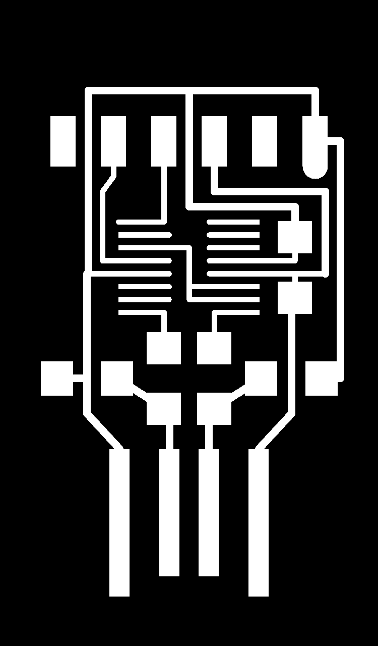
USB-FT230XS-serial.interior.png [png]
-
USB-FT230XS-serial.traces.png [png]
-
USB-FT230XS-serial.png [png]
-
USB-FT230XS-serial.traces.png.rml [rml]
-
USB-FT230XS-serial.interior.png.rml [rml]
-
SAMD11C_serial.ino [.ino]
![[png]](../files_and_codes/files/week04/hello.D11C.serial.5V.1.1.interior.png)
![[png]](../files_and_codes/files/week04/hello.D11C.serial.5V.1.1.png)
![[png]](../files_and_codes/files/week04/hello.D11C.serial.5V.1.1.traces.png)