4. Electronics production – Group Kuriyama
This is group assignment page of Computer-controlled cutting (Kuriyama Student) :
Group assignment
- characterize the design rules for your in-house PCB production process
- extra credit: send a PCB out to a board house
What we’ve done this week
- Surfacing
- Milling the PCB using test data
Surfacing
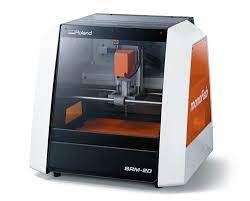
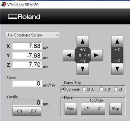
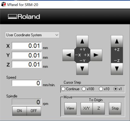
We checked the value of document feed rate per click of DGSHAPE SRM-20.
Cursor Step : Continue
around 7.68mm/ click. But Varies depending on the time of the click.
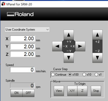
Cursor Step : x100
2mm/ click
Cursor Step : x10
0.1mm/ click
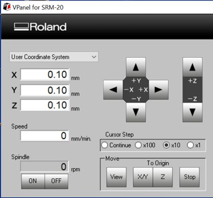
Cursor Step : x1
0.01mm/ click
It is delicate and easily moves up to 0.02mm.
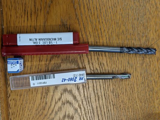
I tried to set a mill. But Carbi Universal’s 1/4inch (6.5mm) mill didn’t fit, and Roland’s 6mm mill is perfect for the collet.
Turn on the SRM-20 first, and then open the VPanel for SRM-20 application.
Measure the size of the chemical wood and connect the lines between the corners to get a midpoint.
Take a origin of the midpoint with XY and z to the chemical wood top.
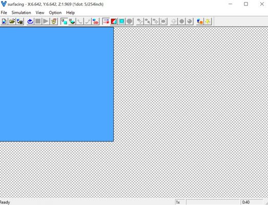
 Start up modelaplayer4 and prepare for surfacing.
File> Choose the file name(Second one from bottom)
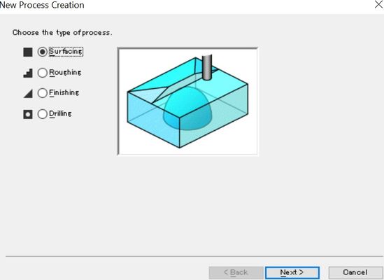
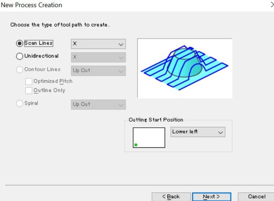
Set> New process Creation or just press the New Process button> Surfacing
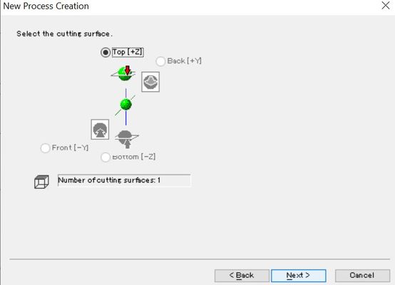
Choose Top [+Z]
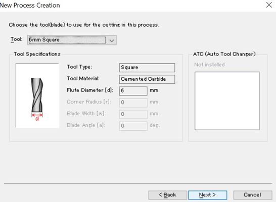
Choose mill size>6mm Square
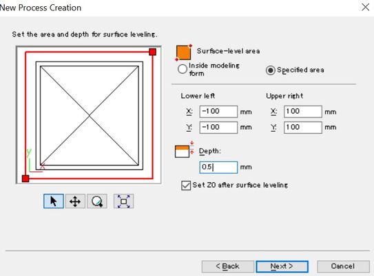
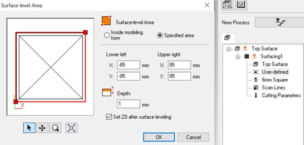
X:200mm Y:200mm Depth:0.5
Choose Scan Lines
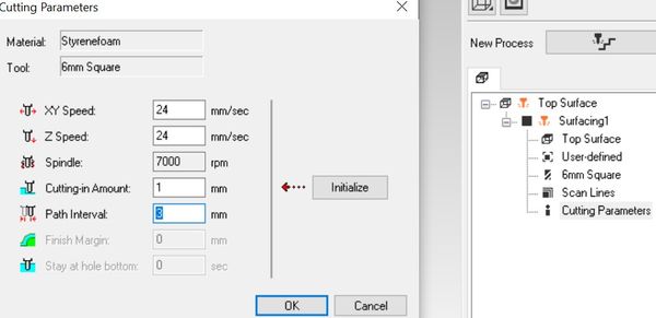
XY Speed: 24
Z Speed: 24
Spindle: 7000
Cutting in Amount 0.6
Path Interval: 1.5
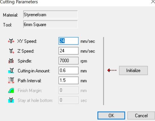
Press OK
Press Cutting View button on the corner.
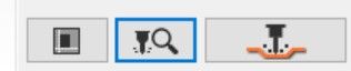
You can see surfacing tab and time in right bottom corner.
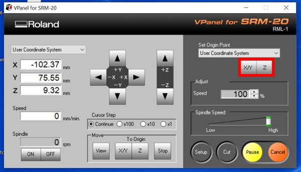
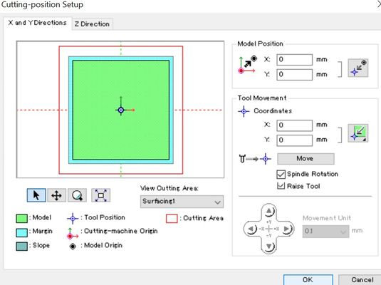
Back to VPanel for SRM-20 and set the Origin.
After set the origin, back to MODELA Player 4
Press the Cut button> OK> Continue
It looks too big area and not deeper enough. It also moved to slow.
So I change some number as follow:
Surface-level Area> X: 170mm Y:170mm Depth:1mm
Cutting Parameters> Cutting in Amount: 1mm Path Interval: 3mm
This time, it just took 15min. And done!!
Milling the PCB using test data
For test data, use the following line_test

Exporting with mods
We used the browser version of Mods.
Flow
Right-click on an empty area of the screen, you can see the following node.
Select “program” ⇒ select “open server program” ⇒ select “PCB png”
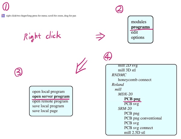
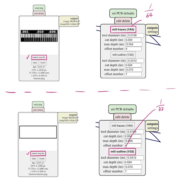
When you select “PCB png”, you can see the workflow as shown below.
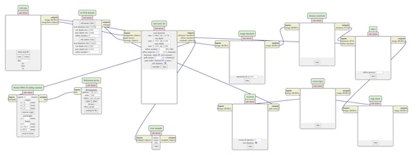
Right-click on an empty space on the mods browser screen can bring up a new node.
modules ⇒ open server module => file save ⇒ Click on the output of the Roland SRM-20 milling machine and the inputs file of the newly created node and connect them with an edge.

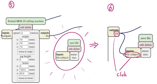
Now that the framework of the flow is complete, we can start entering images and parameters.
Select “Select png file” and choose the png data you want to export.
For line test, select 1/64.
For line test interior, select 1/32.
Change to origin (0,0,0) => Calculate => rml file is exported automatically.
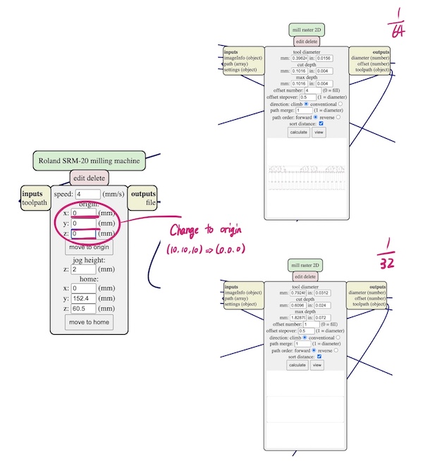
Selecting “caluculate” is open another page in browser, where you can see the following for each
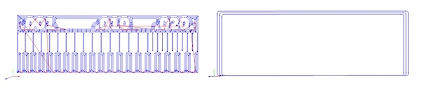
It is also download rml file.
Cut PCB
Use a 1/64 drill for traces cutting and a 1/32 drill for outline cutting

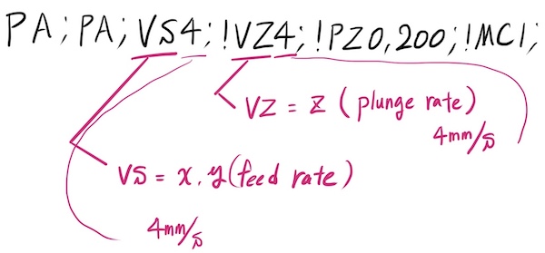
feed rate & plunge rate In the mods, the “feed rate” = 4mm/s, “plunge rate” = 4mm/s (default setting)
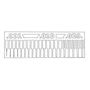
Open linetest.png.rml in a text editor, you can see the line 1
PA;PA;VS4;!VZ4;!PZ0,200;!MC1;
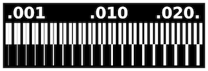
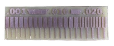
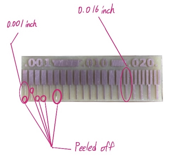
The below copper lines become thin each 0.001 inch from right to left.
We found that the limitation of the milling width was 0.016 inch. By milling the outside of the line, it could leave 0.001 inch of copper line.
It peeled off a little to the 0.006 inch line.
Links to Files and Code
-
linetest.png [png]
-
linetest.interior.png [png]
-
linetest.interior.png.rml [rml]
-
linetest.png.rml [rml]
![[png]](../files_codes/files/week04-kuriyama/linetest.png)
![[png]](../files_codes/files/week04-kuriyama/linetest.interior.png)