6. Electronics design (Indonesia)
This is group assignment page of Electronics design (Indonesia Student) :
Group assignment:
use the test equipment in your lab to observe the operation of a microcontroller circuit board
Equipment test
Specification
Multimeter (Digital Visero 9205B)
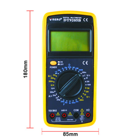
features :
- Maximal voltage between 1000VDC or 700VAC
- Display LCD 1.999 counts - update 2-3/sec
- Measuring method Dual slop integration A/D converter
Osciloscope (Hantek DSO5000P Series)
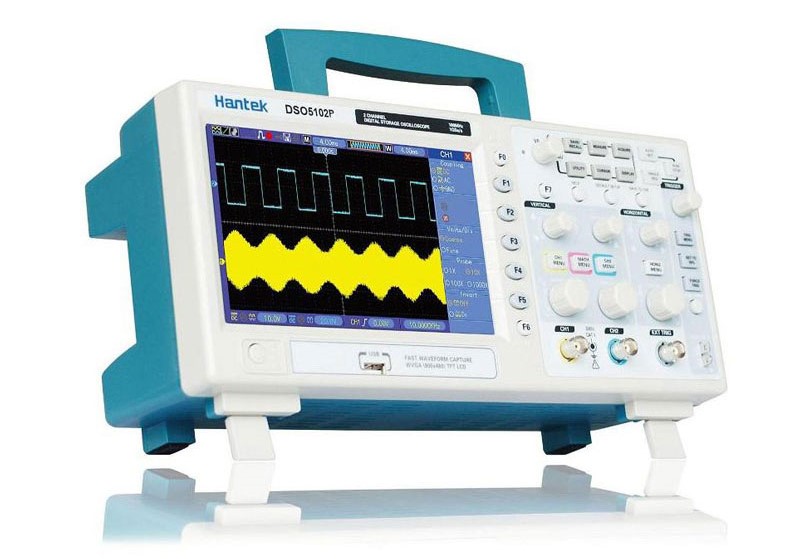
features :
- 100MHz bandwidths
- 1GSa/s Real Time sample rate
- Large (7.0-inch) color display,WVGA(800x480)
- Record length up to 40K
- Trigger mode: edge/pulse width/line selectable video/slop/overtime etc.
- USB host and device connectivity, standard
- Multiple automatic measurements
- Four math functions, including FFTs standard
- Provides software for PC real-time analysisVGA Optional
Testing Procedures
Testing procedure plays as a preparation before using the measurement device. In this task, we use two measurement device which are osciloscope and multimeter. They are standard measurement device in electronics design. An osciloscope can be used to show the signal flows in a curcuit. By using this device, we can see what an multimeter can not see which is abnormalities that might exist in our circuit, for instance ripples on the voltage line. Osciloscope should be self-calibrated prior to using. Every osciloscope is equipped with calibration point that placed on the bottom-right side of the control panel. When we touch a probe to it (along with the ground probe), series of signal appeares on the screen. The standard form would be rectangular signal. This calibration tell us about how good the probe is, how reliable the osciloscope is, how far we can adjust the oscilosope’s display and so on. When we do the calibration, we can get correct voltage as it supposed to be.
VCC test
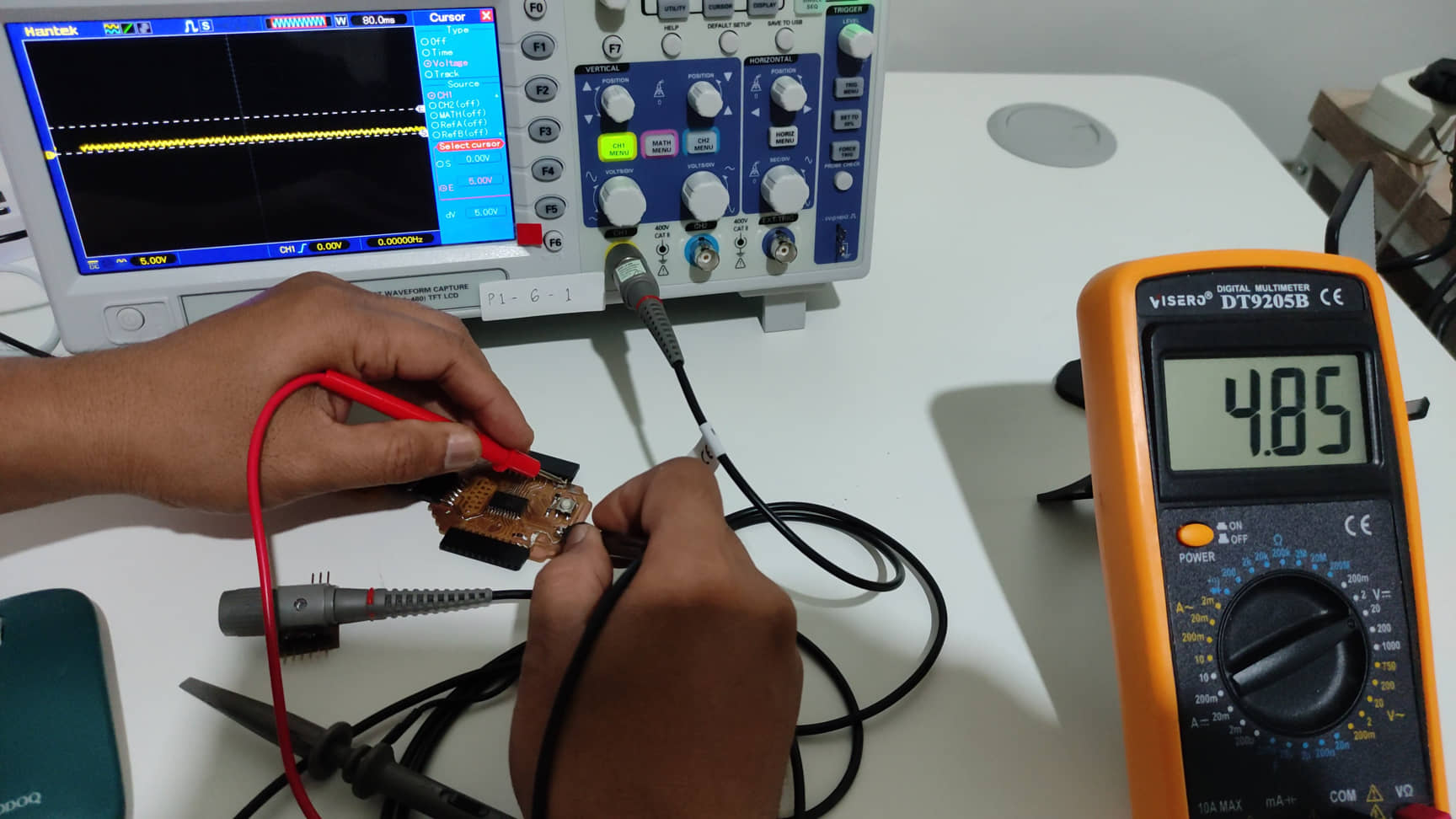
This test is meant to be early phase of building system-based microcontroller. This plays important role to ensure that whole components would get similar voltage (Vcc). The Vcc originally a symbol that describes voltage given to collectore pin in transistor (BJT), while Vdd is a symbol in drain pin in FET. When we measured the Vcc supplied by USB connector from a laptop, similar value appeared in osciloscope and volt-meter which was 4.85 V. This value is enough for the microcontroller operation.
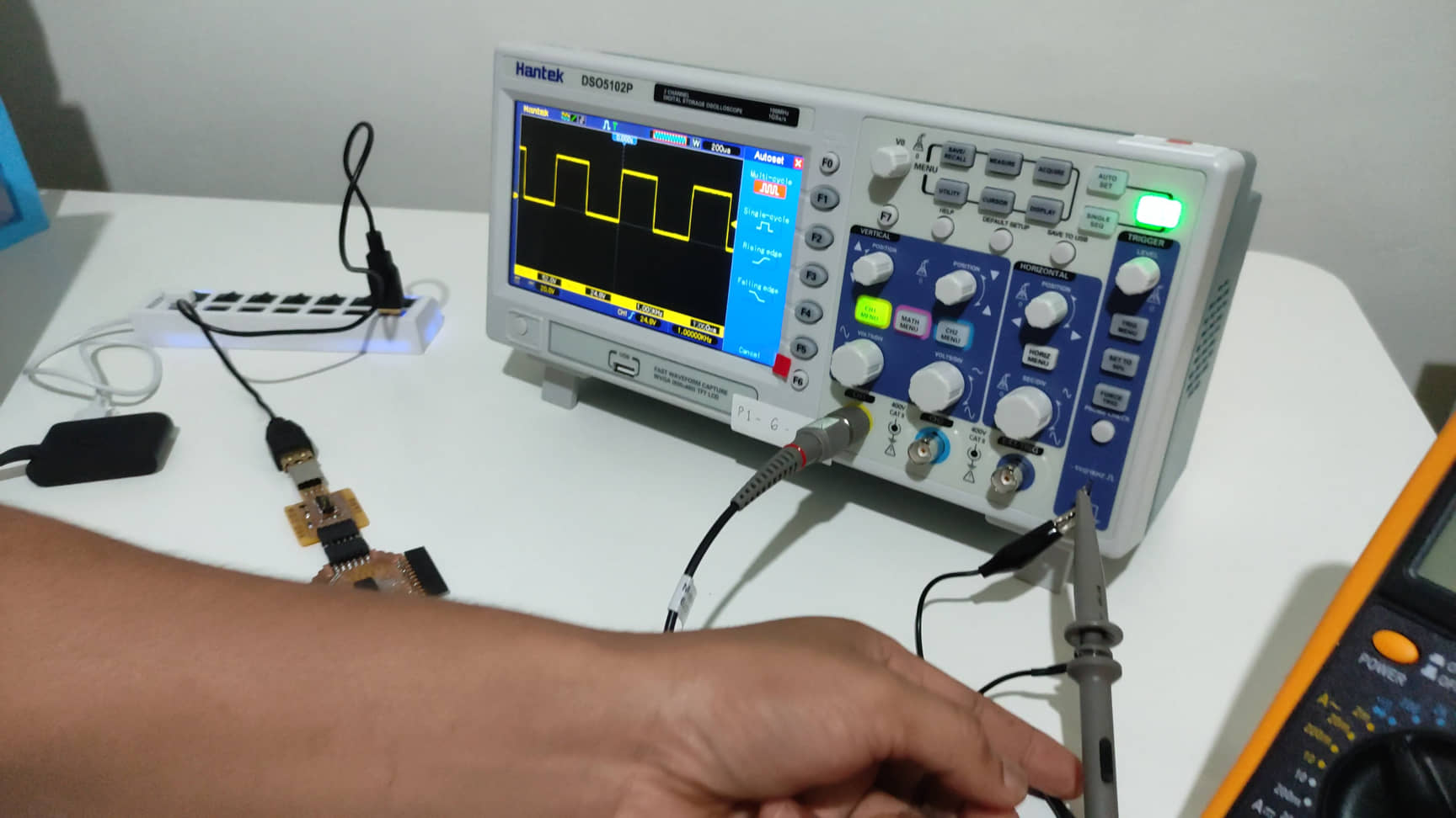
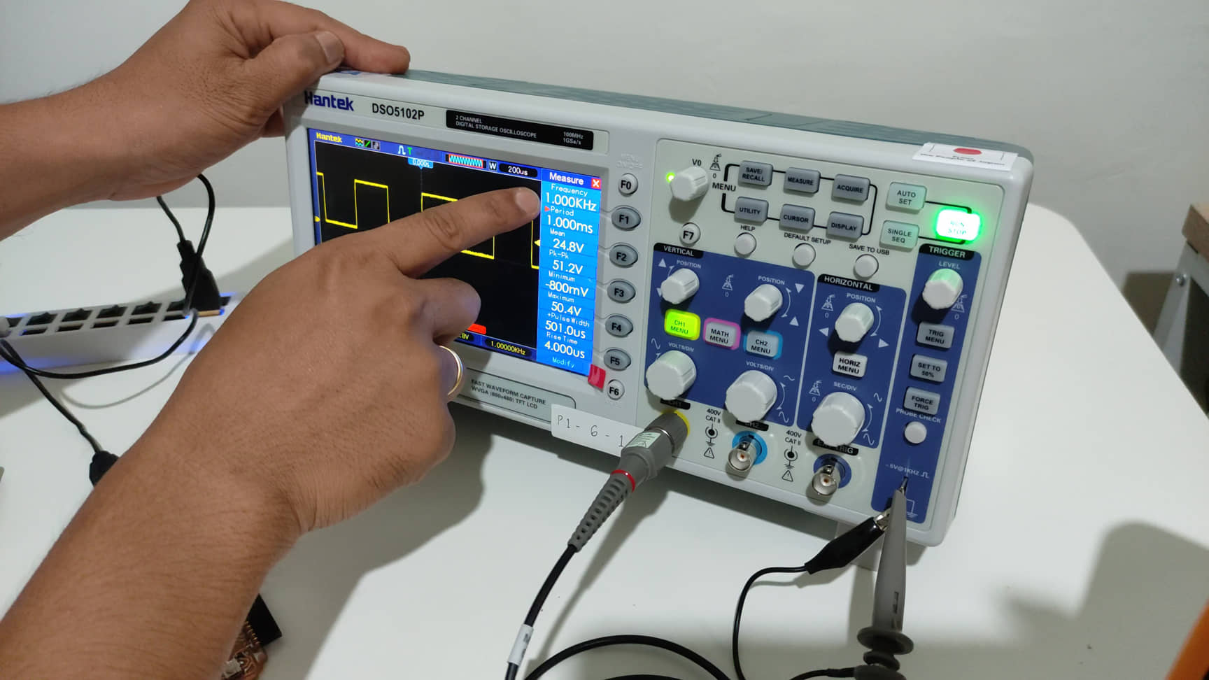
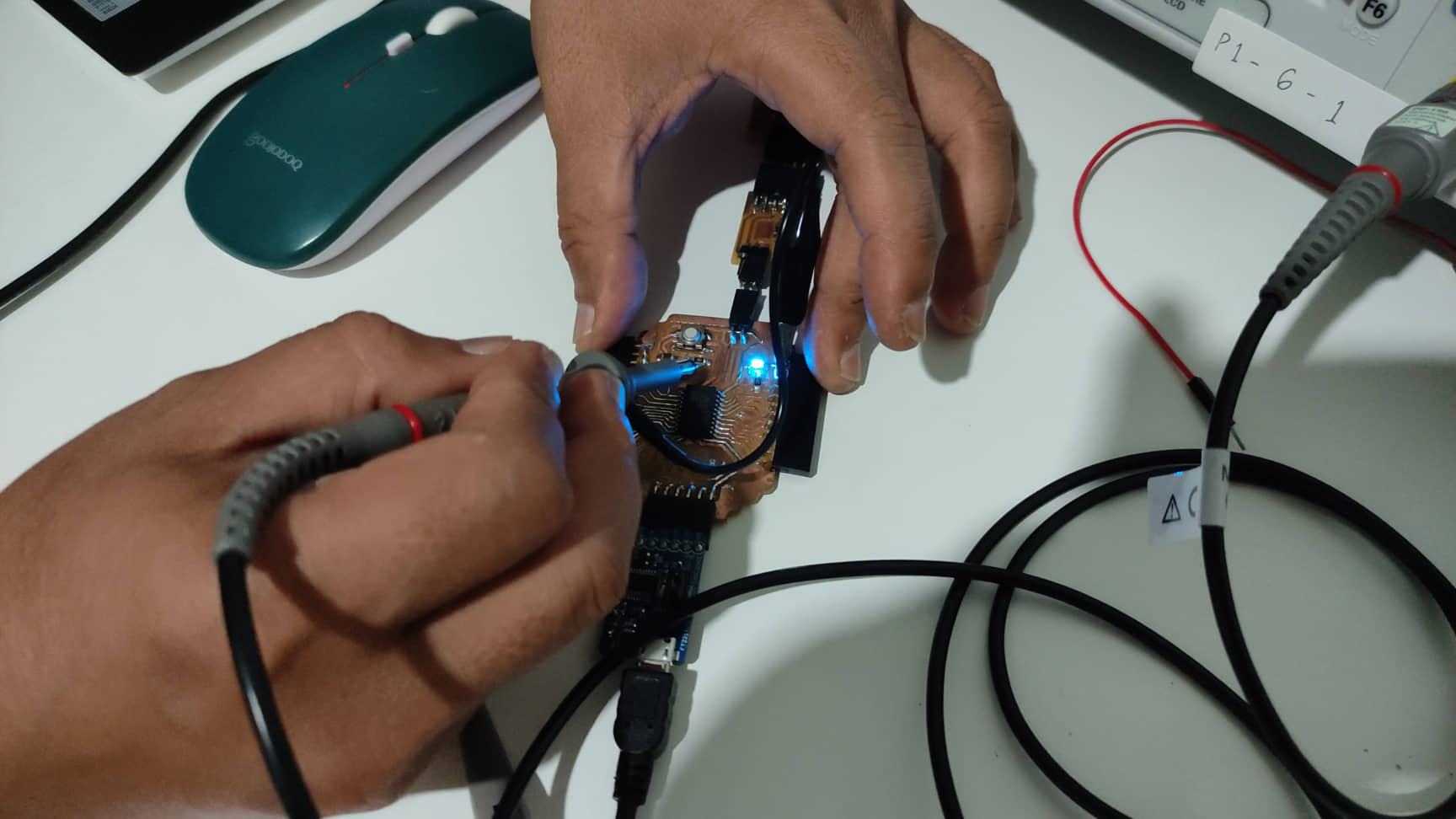
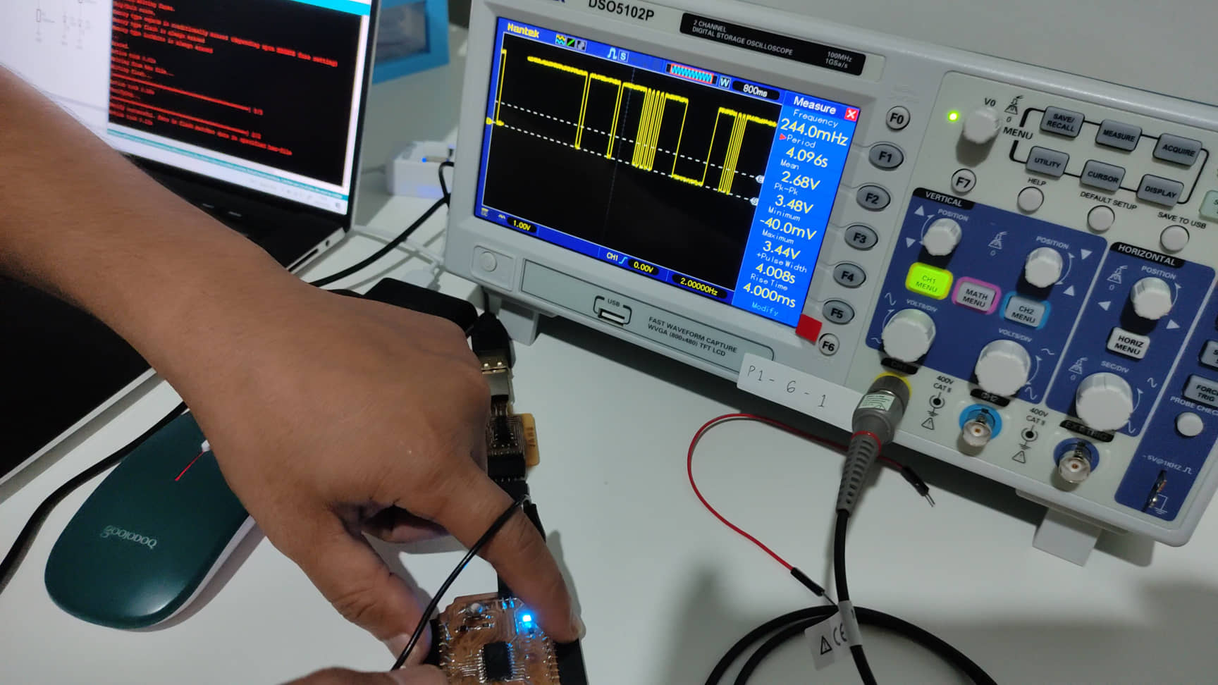
Testing for Blink
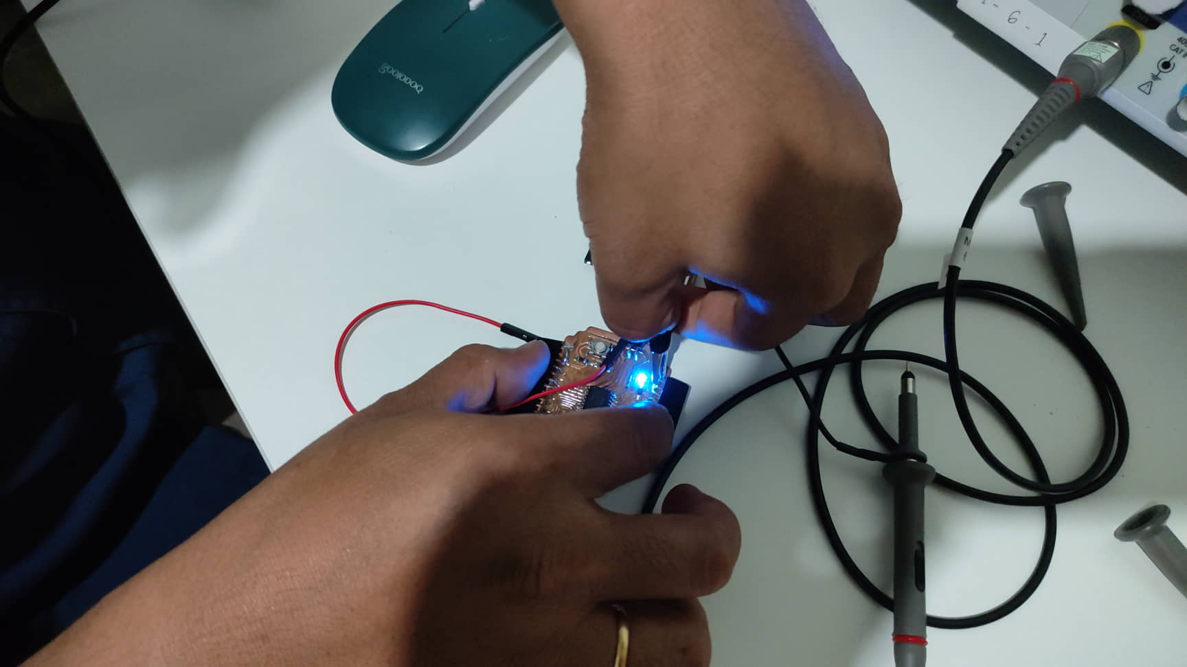
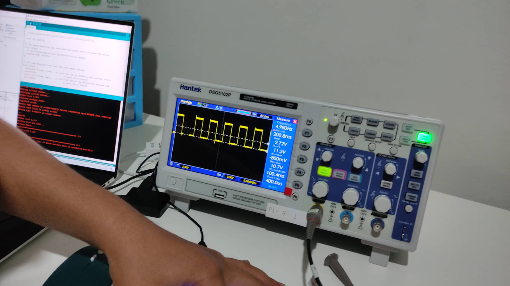
This is a kind of “Hello World” in microcontroller that we used to see in programming world. Led blink is very basic task that microcontroller can do. We use one blue LED as an output of the microcontroller. After uploading the program to micro, we can see that LED blinks with constant time delay. When we measure the signal using osciloscope, it clearly shows what it supposed to be. Series of high-logic and low-logic appeared on the osciloscope screen that indicates we succeed the test.
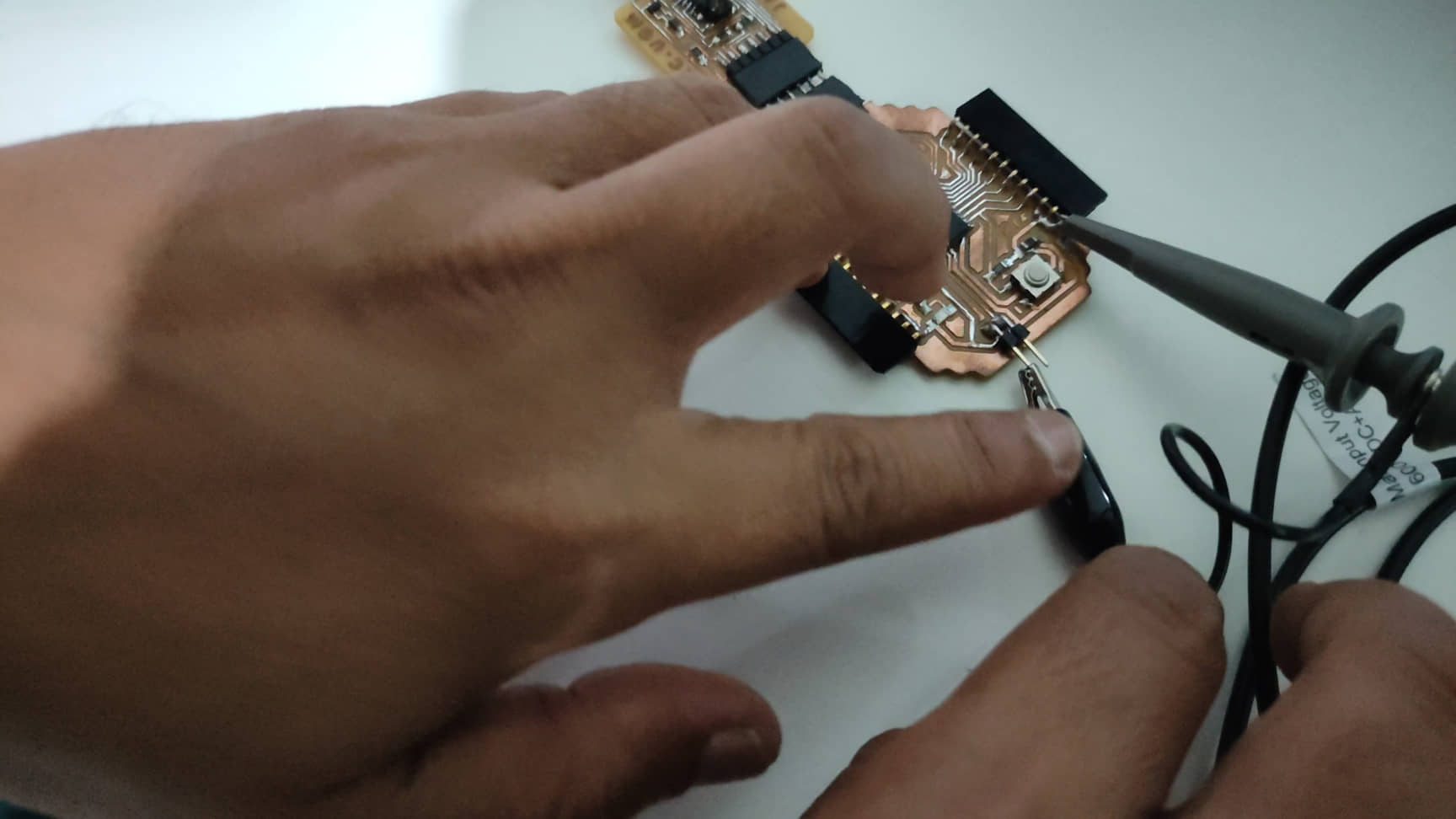
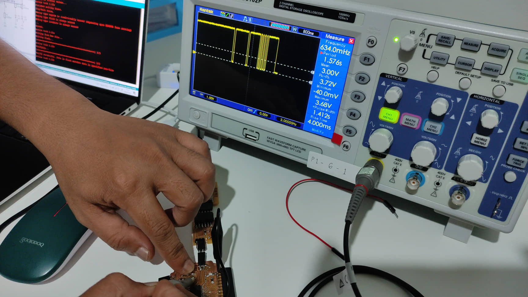
Testing for button-led
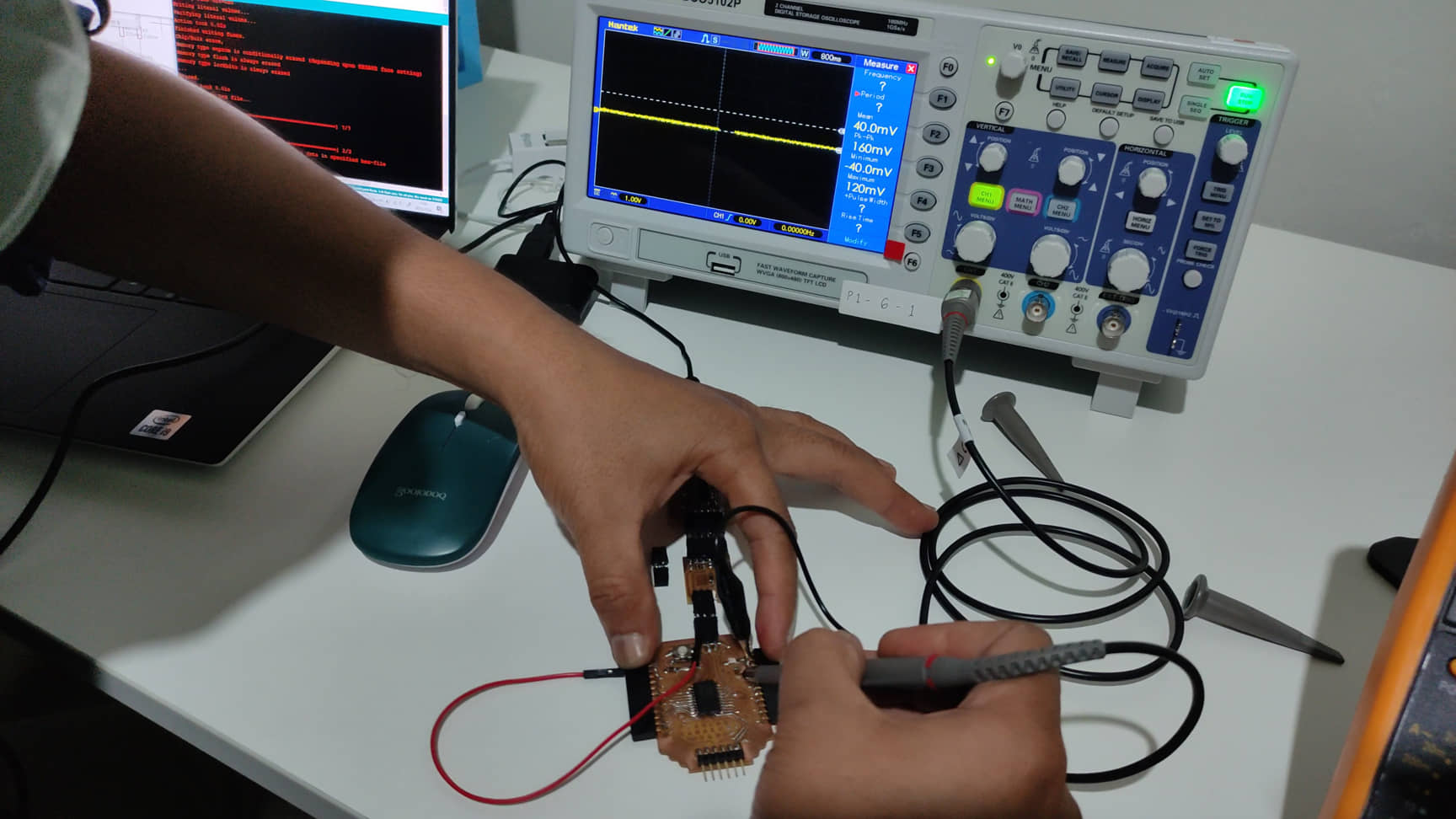
The aim of this test was to check what would happen to the signal went into input pin in microcontroller. When a button connected to pull-up resistor on the circuit was clicked, the electric current flown down to the ground. It makes the osciloscope display a signal that went down from original position which is Vcc. The response of the microcontroller towards value changing is highly fast that the osciloscope can capture. A capacitor is tied to the resistor to avoid bouncing when swithing process on the button happens. Frequent voltage bounces in the digital input of microcontroller can reduce its life time.
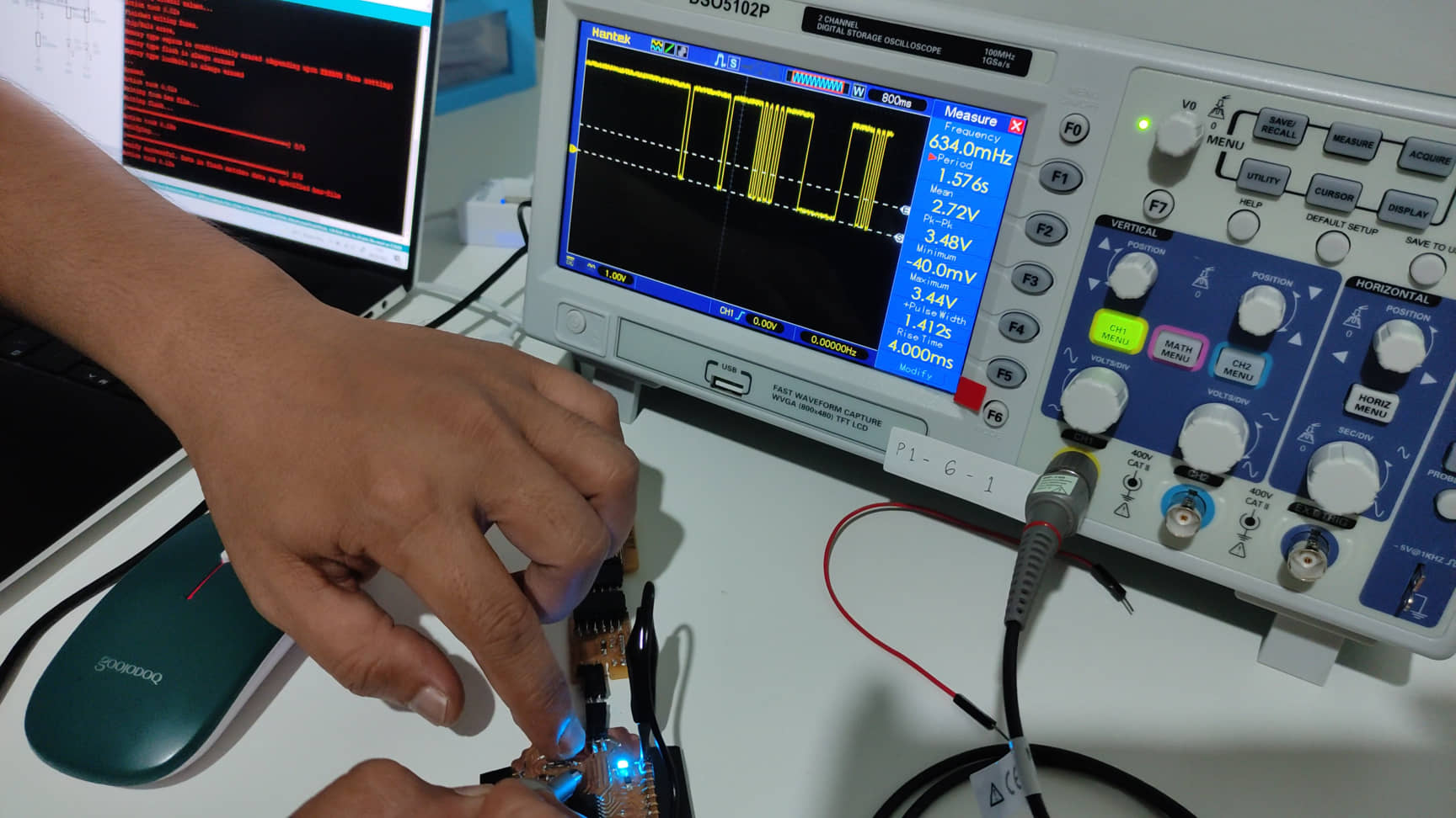
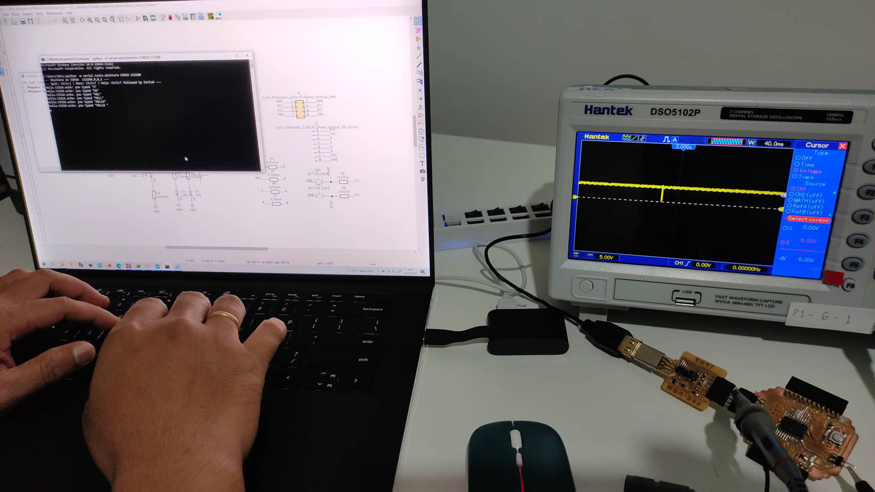
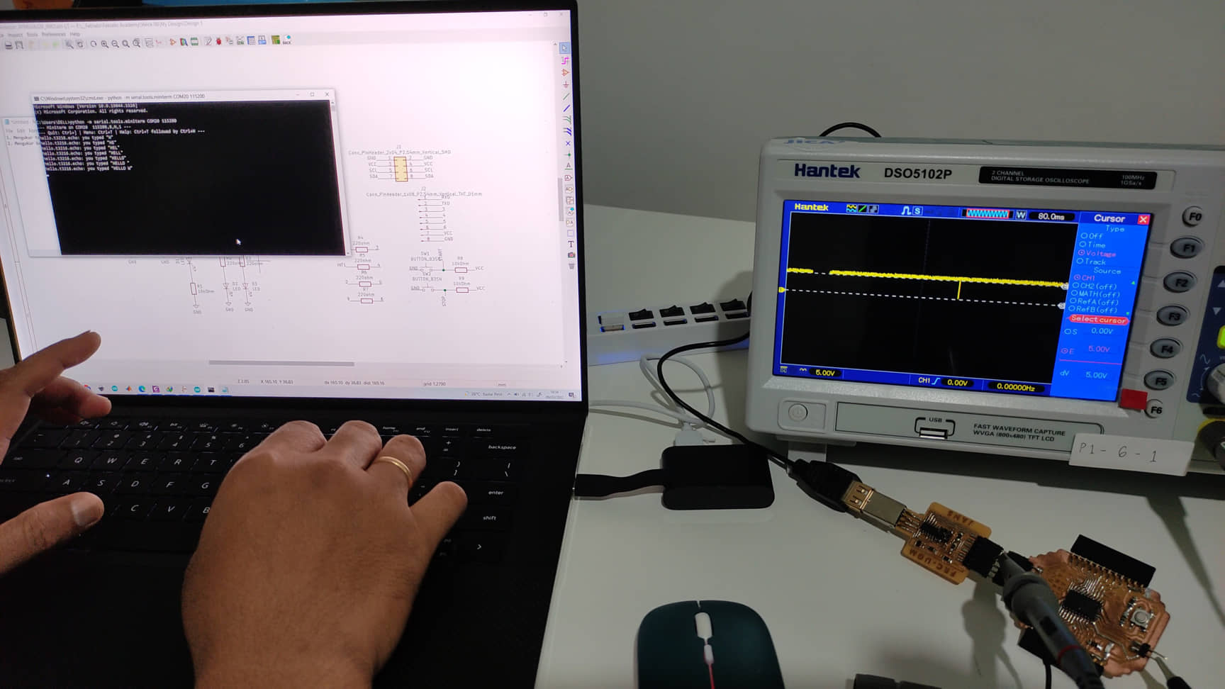
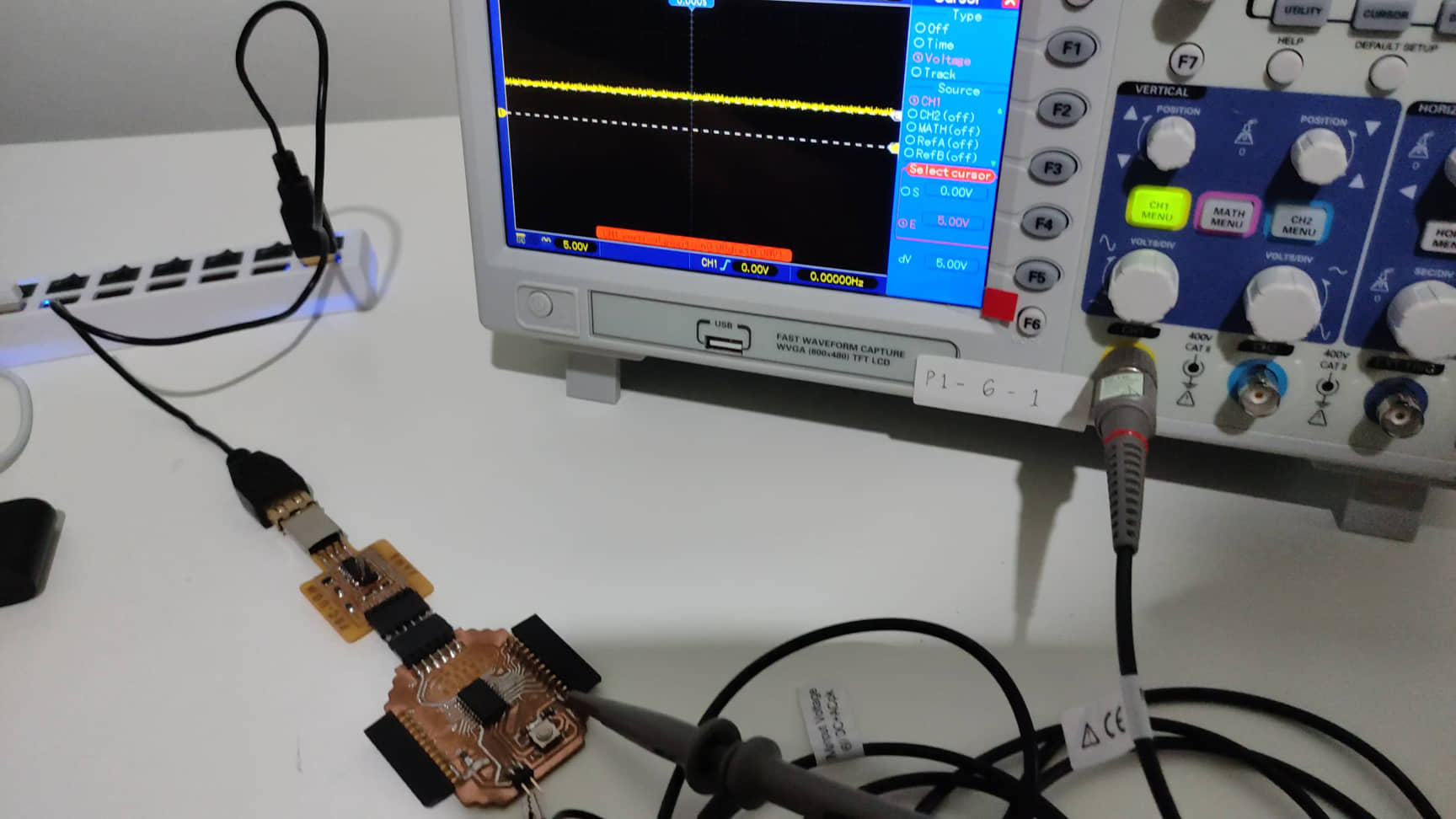
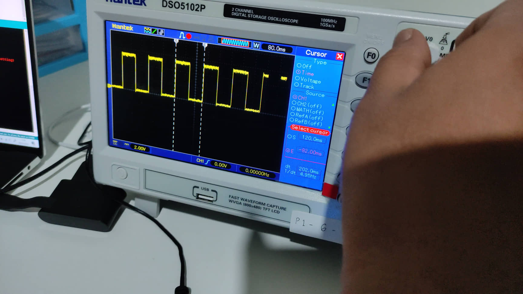
Testing for echo-communications
In echo communication test, it was expected that we could see the series of logical number appeared in the measuring instrument. It can be done only by using logic analyzer. As we know that when data is sent through serial, microcontroller detect them as series of binary number that represent each ASCII code. As we did not have logic analyzer, we keep using osciloscope to see what might appear on the screen. Unfortunately, as shown by below figures, only high logic appeared with short low logic appeared occasionally. We are planning to make our own logic analyzer based on attiny.