4. Electronics production (Indonesia)
This is group assignment page of Electronics production (Indonesia Student) :
Group assignment:
Characterize the design rules for your in-house PCB production process extra credit: send a PCB out to a board house
Characterize the design rules for your in-house PCB production process
Prepare the PCB Design
In this group assignment, we will try to make a PCB with a template, namely testing the cutting path to the smallest path that can be made using the smallest tool we have (1/16 endmill). The image template to be cut (.png) can be downloaded from the lecturer at the Fab Academy in the subject Electronics Production (trace, interior)

Make the G Code for CNC router
After we get the design to be printed, we will use MODS to create a G Code which will be sent to the CNC router machine (SRM-20; rml file).
After we get the design to be printed, we will use MODS to create a G Code which will be sent to the CNC router machine (SRM-20; rml file) - In this Mods we will prepare a program to generate G code calculations for SRM-20, - we also use module to save mods calculation result.
Access MODS here
- After MODS appears, Right-click on the window, select Program -> Open Server Program -> select Roland SRM-20 machine type -> PCB png
-
Also add save modules: Right-click -> Modules -> Open Server Modules -> Save files

-
Connect the file in the mods module with the output file in the mods program
- Create the trace of the path circuit board
- change the origin to be zero (x0, y0, z0)
- load the png file (select the linetest.png file)
- select the mill trace 1/64
- click the calculate button, and then the mod will calculate and make the route
- automatically the file (rml) will be downloaded and we can view the path of route by click the view button
- send to the SRM Machine


- Create the path to cut the board
- load the png file of interior image (linetest.interior.png)
- change to the mill outline 1/32
- click the calculate button, and then the mod will calculate the route to cut
- automatically the file (rml) will be downloaded and we can view the path of route by click the view button
- send to the SRM Machine


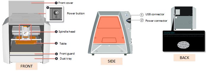
CNC router’s procedure
In Indonesia laboratory. we use a CNC router with the Roland SRM-20 brand. This machine is very good for making engraving for PCB board.

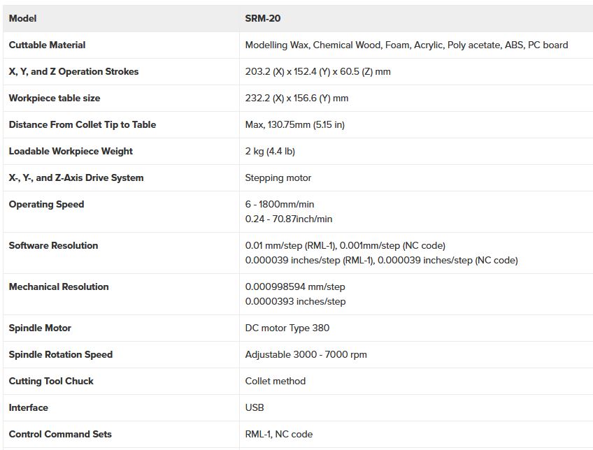
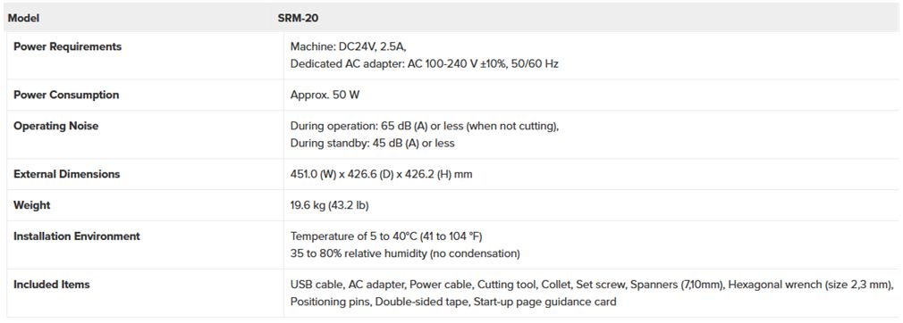
Specifications
The SRM-20E is a fully featured 3-Axis CNC milling machine which provides an excellent resource for one-off 2D and 2.5D projects in plastics and common modelling materials. Output for this purpose is direct from 2D Design V2 using the simple, familiar output routine. The SRM-20E also comes into its own for 3D work.
The 203 x 152 x 60mm machining envelope is very generous for a machine in this class and will allow for most individual student projects. Models can be machined to fine tolerances with an excellent surface finish.
To maximise workflow in a busy workshop, we could usefully create a 3D Rapid Prototyping centre using two or more SRM-20Es rather than a single, higher capacity but more expensive machine.
Machines are supplied with a TechSoft Training Pack and Roland utility software to convert .stl format files for machining.
The SRM-20 portable milling machine can mill a broad range of materials, including modeling wax, chemical wood, foam, acrylic, poly acetate, ABS and PC board.
Multi-axis milling
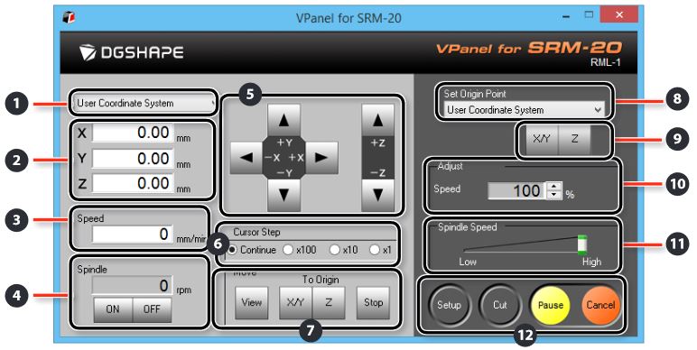
The SRM-20 was designed with a number of technological advancements that include a touch-button VPanel controller to regulate feed rate, spindle speed and milling on a complete X, Y, Z axes, and a new independent collet system that allows for faster setting of the Z-axis base point and quick tool changes.
Support equipments
Some of the equipment and materials needed to make PCBs are: FR1 board, 1/64” end mill (for path routing), 1/32” end mill (for PCB cutting), 3.175 mm collet, double tip, pry, etc..

Procedures
After the program is finished (.rml file), we need to prepare the SRM-20 machine to make the PCB. The procedures carried out are:
-
Install the 3.175 mm collet on the tool holder

-
Installing the table base
- remove the metal table base, to add a wooden base, glue it with strong double-sided tape, position it so that it is in the center of the metal base.
- at the top of the wooden base give enough double-sided tape
- paste PCB FR1 on wooden anvil
- put the metal base back on the machine

- Install 1/64 endmill on collet. Loosen the bolt using an L wrench, install the endmill slightly upwards (remaining flute length is between 5 - 7 mm), tighten the tool retaining bolt.
- Setting datum (zero x-y-z coordinate)
- point the tool to the left-front of the table (position near the minimum x-y axis which is still above the pcb)

- move down the tool until the tip of the tool approaches the PCB surface about 5 - 10 mm (be careful, use the displacement distance scale so as not to crash with the PCB surface)
- after the tip is close to the surface, loosen the tool fixing bolt, hold it with the tool finger so it doesn’t fall, slowly lower the tool until it touches the PCB surface, tighten the tool retaining bolt again.
- press set origin point for X/Y and Z axes (VPanel SRM210 software), answer OK to make sure the coordinates are set to zero.
- raise the tool (Z-axis) sufficiently.
- point the tool to the left-front of the table (position near the minimum x-y axis which is still above the pcb)

- Cutting process
- load the rml file on the CUT menu in the VPanel SRM software
- select the file to be cut, then click OUTPUT, then the machine will operate

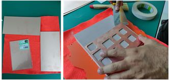
the result :

Milling Machine Characteristics and Results
There are three tools that we use in the process of PCB printing until taking it out from the milling machine which are:
- Big Spatula This tool made of metal and wood (the holder) that help us to take out whole PCB for replacement.

- Small Spatula This tool is so helpful to take out printed PCB as it has smaller edge. In our country, this tool is used by person in service center especially in mobile phone bussiness.

- Brush This tool is used to clean any milling dust after teh activity. All dust will fall to a container beneath the place where milling happens.

We test the milling machine with two combination of speed which are 2 mm/s and 4 mm/s (which is the default). Faster speed should be carefully chosen as it will impact the quality of milling result and the end mill. Smaller end mill like the one we use to mill the trace is very small. Faster speed will push the end mill intensively and would become hotter that could end up (in frequently used with the setting) broken. Speed setting can be done in http://mods.cba.mit.edu/ as can be seen in image below (green-color underline).

The comparison of printed PCB between both speed are shown by image below

Image A and B describe PCB as a result of 2 mm/s and 4 mm/s milling speed, consecutively. When the end mill moves very slow (image A), it milles the trace longer. As a result, the traces become thinner than what we have when faster speed is used as in image B. The difference can be clearly seen visually. The thinnest trace which is 0.001 inch in image A is exfoliate from PCB board while in image B the trace is glued. We tried to sweep our finger after some of time on 5 thinnest traces on both PCB, we observed that some of the traces are exfoliate. We conclude that, we cannot count on thin traces when making PCB with SRM-20 as it can not glued in a long time.

When we use MODS to create coordinates for milling machine, it will output a file with RML extension. All the settings we set in MODS are written in it. Take a look at below snippet image that shows settings are written in symbols. For example, VS4 and !VZ4 describe the speed that we set which is 4 mm/s while 200 is the JOG height in milimeters.

Important Link as Refernces
-
https://www.rolanddg.co.jp/products/3d/srm-20-small-milling-machine/features
-
https://downloadcenter.rolanddg.com/contents/manuals/SRM-20_USE_EN_R4.pdf