8. Embedded programming (Indonesia)
This is group assignment page of Embedded programming (Indonesia Student) :
Group assignment:
- compare the performance and development workflows for other architectures
In this weekly group assignment, we use development board that we already have. All the boards that we have actually are programmed with different programming language and software. But we were thinking, is it possible to make them working in the same platform, which is Arduino IDE? As we realize that this platform is popular and frequently used by many hobbyist, engineer, and researcher for their simplicity. It takes little bit longer than previous assignment to finish as we need to dig deeper into many resources to get appropriate file and workflow to make these boards work on the same platform which is Arduino IDE.
Three LED and One Button
In this test, we made our own board with three LEDs (different colors) and one tactical button as can be seen below. When building this PCB, we also realized that we found a fit radius for THT (Through Hole Technology) component, for instance pin header, which is 0.8 mm. Previously, we use 1 mm radius and end up with bigger hole created by the endmill. The reason is when we use 0.8 mm radius, the endmill will only touch the hole once as we are using 1/32 endmill (= 0.7xx mm). But when we use 1 mm, the endmill will be rotating inside the hole since the discrepancy between radius of endmill and hole-through around 0.3 mm. Figure 1 is a drilled PCB with radius 1 mm, whereas figure 2 with radius 0.8 mm.
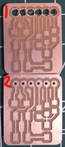
Also, preparing RML file in MODS is little bit tricky. The key point of creating appropriate RML file is the DPI value. Value less than 2000 can not bring whole drill holes, so we use 3000 at the end as shown by figure below.

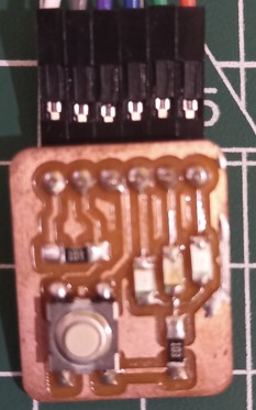
With three LED (red, green, and yellow) connected to only one resistor 10K, a pull up tactical button and 10K resistor, the realisation is shown by figure below.
Esp8266
This board is the simplest amongst the other. We did not meet any difficulty to make this work as it is popular few years ago. The board that we use is Lolin (NodeMCU V3) from wemos.com.
Here are steps that we use to make this board able to be programmed with Arduino IDE:
-
In FILE->Preferences open Additional Boards Manager then put in
http://arduino.esp8266.com/stable/package_esp8266com_index.json
You can also add ESP32 into it.
https://dl.espressif.com/dl/package_esp32_index.json
-
If you are not sure about your board type, you can choose
Generic ESP8266 Module
We can leave all parameters in default mode.
- Then click verify->compile button on Arduino IDE. The uploading is succeed when screen below appears.
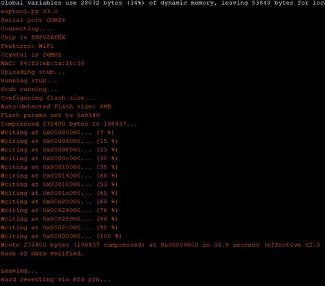
-
Then we connect our Butten-3 LEDs to programmed Esp8266 and test it. Our program works to control LEDs blinking by their speed (delay). There are 3 combinations that we set to one button.