3. Computer controlled cutting (Indonesia)
This is group assignment page of Computer-controlled cutting (Indonesia Student) :
Group assignment:
Characterize your lasercutter’s focus, power, speed, rate, kerf, joint clearance and types
In the laboratory that will be built as a Fablab at Gadjah Mada University (Yogyakarta, Indonesia) using a Trotec Speedy 100 Laser Cutter.

Specification Trotec Speedy 100
Operational Procedures
-
Design Process
- Laser cutting design is done for cutting (cutting) or engraving (engraving)
- Design object using vector based design software (Coreldraw, Fusion 360, Inkscape, etc.z)
- The maximum dimensions of the object that can be worked: 30 cm (l) x 60 cm (w)
- Engraving Process
- The object can be a line or an object that contains (fills, vector images, letters, etc.)
- The color of the object is made “black”
- Other color alternatives (gray scale) will cause the carving intensity
- Cutting process / material cutting
- The object of the image is created using a line with a thickness of “Hairlaine”
- The color of the object/line is made “red”
- No double lines (avoided)

-
Preparation Machine
-
Turn on the power supply (Stabilizer, Switch Trotec 100, Filter )

-
Turn on the machine “on” switch on the back (top) of the machine
-
Place the material to be worked on on the machine (on the honycomb base), the maximum material is 30 cm x 60 cm

-
Point im the laser eye position on the object by pressing the arrow buttons on the machine

-
Adjust the laser eye focus height using the height tool by pressing the height arrow until the height tool hits the material object

-
Position the laser at the place / area of the object to be cut. It is necessary to consider the size of the design that is cut with the size of the object’s availability
- Printer ready to use
-
-
Printing process
- Setting up printing properties, from the design software select print (Ctrl-P), select Trotec Engraver

b. Setting the “preferences” printer

c. Click OK, then give the name of printer object, open the Job Control
d. Setting the Job Control
- Make sure the “job control” is connected to the machine
- Once the laser position is placed the laser position mark will be visible on the JobControl.
- Attach/drag the Jobname to the area to be printed (laser cursor). The black block indicates the area to be lasered. Press the “eye” icon to see the preview
- Press the Play button to print.

the result :

We made a video about Laser Cutting Procedure (but in Indonesian)
Characteristic Laser Cutter
Laser cutting is a material cutting process that utilizes a laser, producing high quality, dimensionally accurate cuts. Laser cutting works by directing a high-power laser output through a nozzle to the material in a localized area. CNC (Computer Numerical Control) is used to direct the resulting laser beam, so it is often also called CNC Laser Cutting. Commercial lasers for cutting materials use a motion control system to follow the CNC or G-code of the pattern to be cut on the material. A focused laser beam is directed at the material, the combination of heat and pressure creating a cutting action. The material will melt, burn, vaporize, or be blown off by gases, resulting in an edge with a high-quality surface finish.
Each laser cutting machine has different characteristics (Power, Speed, Rate) to the cutting properties of certain materials. In this machine we try to make engraving and cutting characteristics for certain materials so that they can be used as references in operational procedures.
Laser Focus
When the focus of the laser cutting machine is in the best position, the slit is small, the quality cutting efficiency is the highest, and the best cutting effect can be obtained.
Different cutting focus positions correspond to different cutting surface roughness, and the cutting quality of laser cutting machines is largely determined by the relative position of cutting focus and cutting plate. (Jack Zhou, 2021).

Laser Power
The power laser cutter shows how powerful the laser is used to cut the material. The greater the power, the more possible the laser’s ability to cut thick materials. The use of power needs to be adjusted to the material and thickness of the material to be cut. If the power is too large, the material will burn and scorch, but if the power used is too small, the material cannot be cut. So it is necessary to regulate how much power is needed to cut or engrave a certain material.
Speed
The speed of motion used when the laser is cutting will also affect the quality of the cut and the engraving. If the speed is low, the amount of energy imposed on the material will be more and more, so the material can be burned, while if it is too fast, the amount of energy captured by the material will be less. Therefore, it is necessary to test the power and speed to produce good cutting and engraving quality for each material.
Pulse Rate
The PPI parameter (=pulses per inch) determines how many laser pulses per inch are used for the laser engraving. This should be the same or a multiple of the dpi selected in the print setting to ensure that you achieve a good result. If you set this parameter to “Auto,” JobControl automatically determines the optimal resolution of the laser pulses. During the laser cutting process, Frequency is a decisive parameter and is given in Hz (=Hertz). It specifies the number of laser pulses per second. In a CO2 laser machine, the value can be set within a range of 1,000 to 60,000 Hz.
Test power and speed
Test design
The first step is to design a shape that will be tested for speed and power. We make two models for the engraving and one model for cutting. The materials to be tested are 3mm Acrylic and 2.5mm MDF board. To vary the speed and power we need to create a color definition that will be set in the Job control. The color definition follows the following figure:

Next we adjust the shape that we will engrave and cut according to the specified color.

Laser cutting Process
After the design finish, we process the laser cutter machine :

Results
The results from the test : - Engraving : MDF Board, 2.5 mm :

- Cutting : Acrylic, 3mm :

- Cutting : MDF Board, 2.5 mm

From the pictures of the results of the graving and cutting tests for speed and power variations, it can be seen that the amount of power will make the material flammable, so the fiberboard looks black. While the slow speed makes the amount of energy received by the material increase (per unit time) so that it also causes the material to burn (black).
The use of large power will reduce the service life of the machine, so the recommendation is to use power, not at the maximum value (100%). Likewise, the faster the speed, the faster the work process will be (reduced production costs).
However, if the power is insufficient or the speed is too high, the material is not cut perfectly or the engrave does not look optimal, it is necessary to find the optimal value for power and speed for each type of material and a certain thickness. For example, for a 2.5 mm MDF fiberboard, we can choose a 60% power configuration with a speed of 5-6, or 70% power with a speed of 6-7. This will make a good cut (not burnt).
Laser cutter kerf
When the laser cuts material, it burns a small amount of that object material – this is what is called laser cutting kerf. The number of kerfs depends on the type and thickness of the material, along with several other variables. So that when the material that intersects will be paired, this needs to be considered so that the matched pair can fit.
I try to fit the design on the slot pairs by combining the slot size with the nearby tolerances. To make a test fitting, we can use the following tools:
Kerf Check Parts Generator (by Doyo-sensei)
The slot designs tested are sizes 2.5 mm and 3 mm
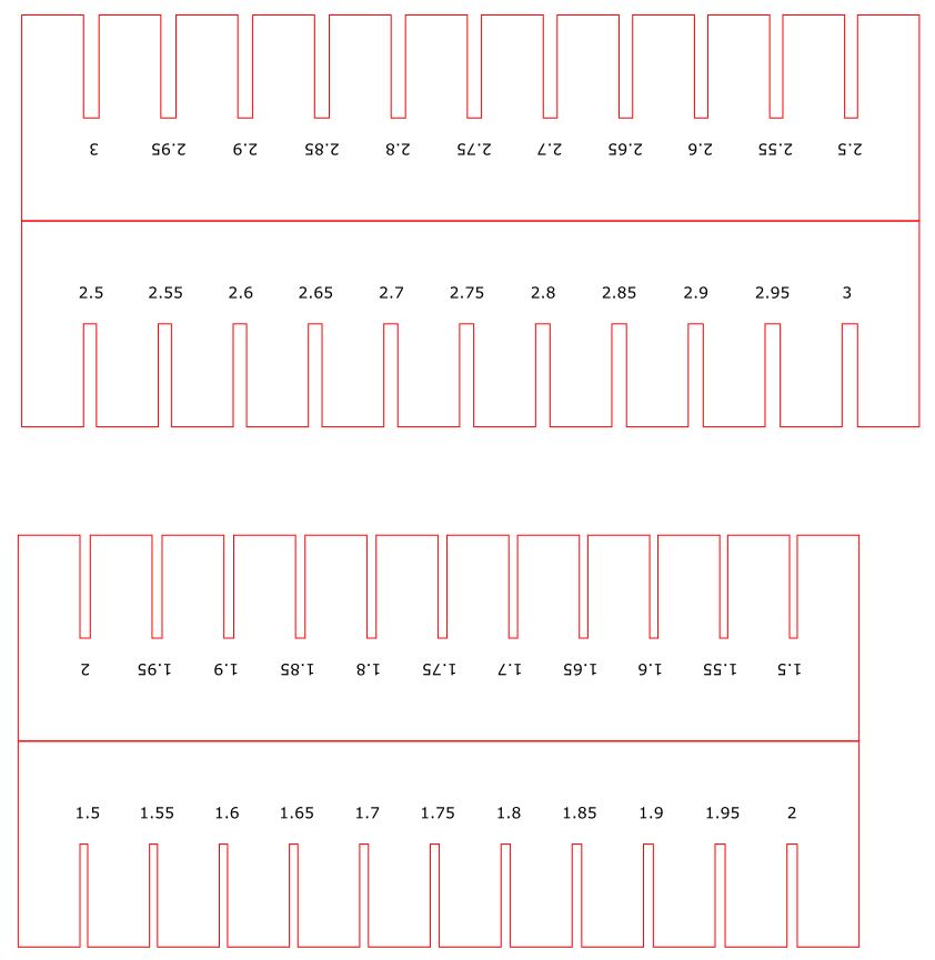
In the “KERF” test, we tested the design for fiberboard material with a thickness of 2.5 mm. We will cut this design with two variations of power and speed. the first cut with 60% power and speed 0.6, while the second cut with 100% power and speed 0.1. The result is shown in this image
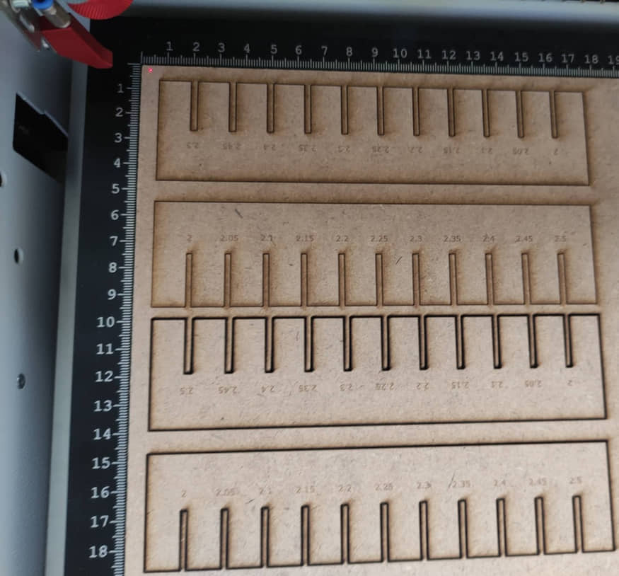
After being paired with each other, it is seen that there is a gap due to the burning of the material when cutting. So there needs to be a fit to the right size for a certain thickness value (2.5 mm).
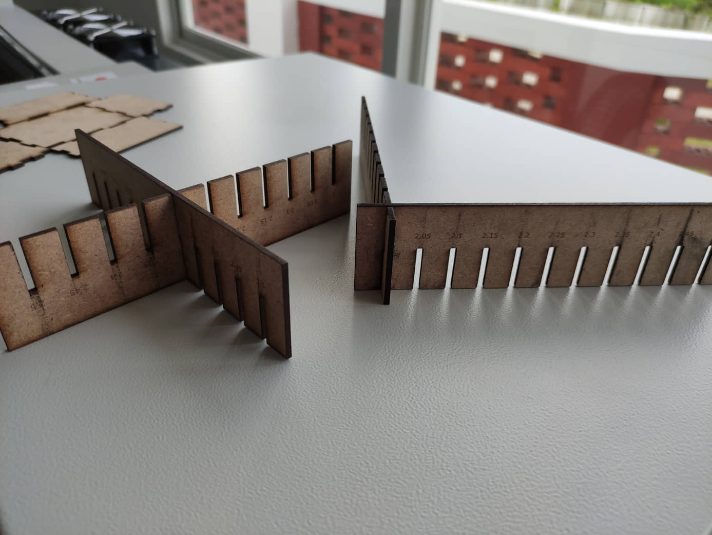
When measured using a caliper, it turns out that the thickness of the fiberboard (MDF) is 2.4 mm.
- Power 100% and speed 0.1: obtained for the fit setting is at a size of 2 mm, there is a difference from the thickness / original size of 0.4 mm.
- Power 60%, and speed 0.6: the fit setting is found to be at a size of 2.35mm, there is a difference of 0.05 mm.
This shows that if the minimum power and maximum speed settings will reduce the Kerf effect. This setting refers to the cutting settings table discussed earlier.
Laser Cutter Material
For a particular material, a laser cutter user may identify the optimal power and speed setting for cutting and rastering quickly and cleanly. However, varying from these settings allows the user to perform diagnostics, compensate for the condition of the laser lens and air quality, balance the needs of speed and accuracy, and intentionally create partial cuts and aesthetically different rasters.
The goal of this laser cutting exercise is to test a range of machine settings and qualitatively identify the range of varyingly acceptable parameters.
Potentially Hazardous Materials
Many materials can potentially be significant hazards to laser cut as they can damage the laser cutter, catch fire, or emit toxic gases. In some cases if the laser cutter has the proper ventilation equipment these materials can be cut safely, but it is necessary to verify that the laser cutter is properly outfitted to handle the material. Below is a list of materials that can be dangerous to laser cut.
-
Materials containing halogens (chlorine, fluorine, etc.) such as PVC, Neoprene, and Teflon
-
Polycarbonate (PC)
-
Materials containing styrene such as polystyrene, styrofoam, thermoset polyester, and ABS
-
Stone, ceramic, or other porous, hard materials
-
Materials containing Nitrogen bound to Carbon (a CN bond) such as nylon, ABS plastic, polyurethane and some acrylics
-
Fiberglass composites
-
Carbon fiber composites
Safety in Process
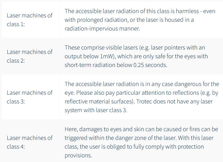
Laser machines are divided into internationally valid classes based on their performance and the risk of injury for eyes and skin connected therewith: Class 1 offers the highest safety. With lasers of class 4, laser radiation can be emitted. The use of protective equipment (e.g. protection goggles) is necessary here. Trotec laser machines contain a CO2 or a fiber laser source, or both laser sources in the Speedy flexx systems.
How safe are Trotec laser machines?
By means of the closed design of the Trotec lasers, the laser user is optimally protected. This concept additionally allows for rapid and efficient extraction of dust and gas. The closed Trotec flatbed laser machines belong to laser class 2.
Why only laser class 2? Laser pointers are built into Trotec lasers, in order to show the user where the laser impinges the material. According to the internationally valid standard, laser pointers with an output of less than one milliwatt belong to laser class 2.
Classification of the laser safety classes:
Protective cover
For all closed laser systems, e.g.: Speedy Laser Engraver series or SP Laser Cutter series, the acrylic cover provides extensive protection from the laser light. Depending on the laser source, different protective covers are used. For example, laser machines with a CO2 laser source have a blue acrylic cover, while machines with a fiber laser source have a green cover. Due to the coloring of the acrylic glass, the laser light is completely absorbed, thus providing extensive protection for the laser user.
Temperature sensor with warning signal
Some materials (e.g. acrylic) tend to flame, especially during laser cutting. The specially developed temperature sensor alerts the laser user when the temperature in the work area exceeds a critical value. The operator can react instantly to the acoustic warning signal and interrupt the laser process. Nevertheless, laser machines should never be left operating unattended. More about the temperature sensor
Safety switch for immediate interruption of the power supply
In a dangerous situation, the power supply can be interrupted by means of various safety switches and buttons. The laser process is immediately stopped.
- Main switch: Main power supply is disconnected
- Key switch: Motor, laser source and electronics are de-energized
- Emergency stop button: Electric circuit is interrupted, the laser beam and all movements are stopped