Useful links
- Programmers Summary ✔
- GitHub repository of Programmers and Serials ✔
- Interesting approach using SAMD as a Programmer ✔
other comment
This week is not over yet and it has been the most exciting for me so far. We talk about electronics production, finally something more relevant to my field of study.
Before starting I want to give a little update on my situation here in Barcelona, I found a room but the landlady kicked me out because I asked for the right to use the kitchen for breakfast, lunch and dinner. Instead she allowed to use it only once a day in order to prepare lunch and dinner together. And now there are problems because I don't think she wants to give me back all the money of the deposit and part of rent of the first month, I hope I wont need a lawyer.
Hopefully soon I'll do a video about this story because I think it is a very interesting life experience.
Now let's talk about something more interesting!
Microcontrollers are specific chips dedicated to one task and run one specific program.
They are used for example in the use of applications where a very accurate timing is required, like in servo motors.
They differ from microprocessors which instead have a more computational power and which can run different programs.
Moreover, unlike microprocessors that only work with specific voltage levels, Microcontrollers run on a range of voltage and are often low-power devices.
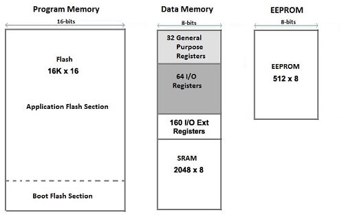
As the image above shows, we can generally divide the microcontroller memory into 3 parts:
During the class lesson we were presented with 3 families of microcontrollers, before listing them it should be noted that each brand new chip just out the factory usually has an empty memory, therefore the chip cannot be used.
In order to use it you need a Programmer to burn a bootloader in it.
A programmer is basically another device (which can be a microcontroller of the same type of what we have to program) that has been specifically programmed to install codes and bootloaders.
The purpose of burning a bootloader is to enable the uc to connect to the outer world, (a PC for example) transferring a new firmware into the main part of the flash memory.
During my experience with the Arduino and ESP family I used Arduino UNO as programmer for both ATTINY85 and ESP32-CAM.

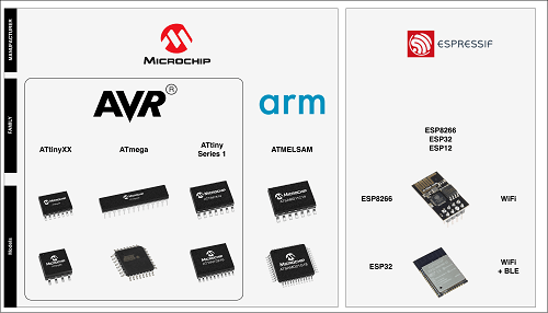
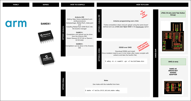
Let's now proceed with the list of microcontrollers that have been presented to us so far:
ATtinyXX where the first X is the memory in KB the chip har you can program them with the ISP protocol (6 cable):
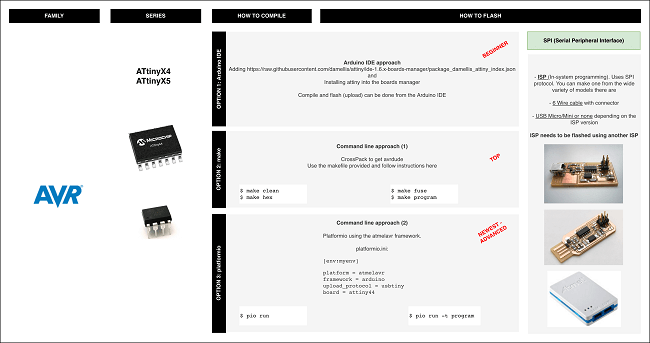
PWR; GND; Reset; Sck (clock, to sycronize the speaking with another device) and MISO and MOSI (Master Input Slave Output).

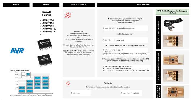
New family of Attiny AVR XX XX (first number is the memory, second the num of pins).
You can program them with a new protocol: UPDI (Unified Programming Debbuging Interface), It's a simplified version of the ISP that needs only two wire aside from Power rail.
ARM family that became very easy to program as the new family of ATtiny, they have more capabilities and processing, still remaining very cheap and also the come with NATIVE USB INTERFACE that means you can program them directly from a computer while the ATtiny need a programmer instead. But in order to do that you need to program it at least once with a Programmer first. This will be the microcontroller we will use the most in our course.
So what basically we are gonna do?
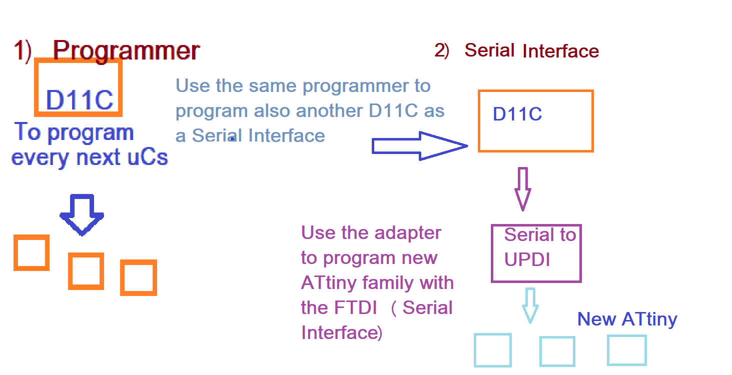
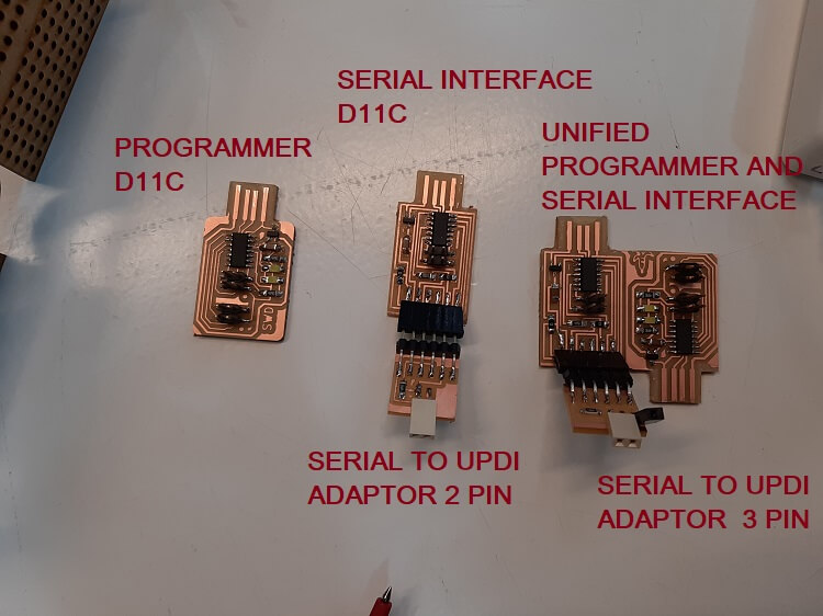
First, make a programmer with an ARM ucontroller so that we can programm all the ucontroller we will need for our future projects and assignments.
Second, we use another ARM to make an FTDI to work as a Serial Interface.
A serial interface is a device used to send data collected by the microcontroller (such as values from a temperature sensor for example) to another device (such as a computer). It is not possible to use a Programmer for this kind of tasks as it works unidirectionally while the Serial interface works bidirectionally. We will use the programmer we did before to program the second ARM as an FTDI.
Notice that with the FTDI we can also program (bootloader included !!) all the new series of ATtiny chips, that's because they use the UPDI protocol that is capable of that, instead of the ISP that cannot.
That's why as a third circuit, we're going to make a FTDI to UPDI adapter.
Why do we need both? Cause UPDI it is useful to upload bootloader and program, but not as serial interface.
Looking through the ready-to-mill files fo the schedule, I also came across the FTDI-to_UPDI adapter but with 3 output pins, the third is to give a different power supply voltage, which could be useful since sensors and microcontrollers can work at different voltage levels.
Enough of all this theoretical tangle? let's move on to the facts and make some PCBs (Printed Circuit Boards) that differ from PERF-boards, the only boards I worked with my whole life.
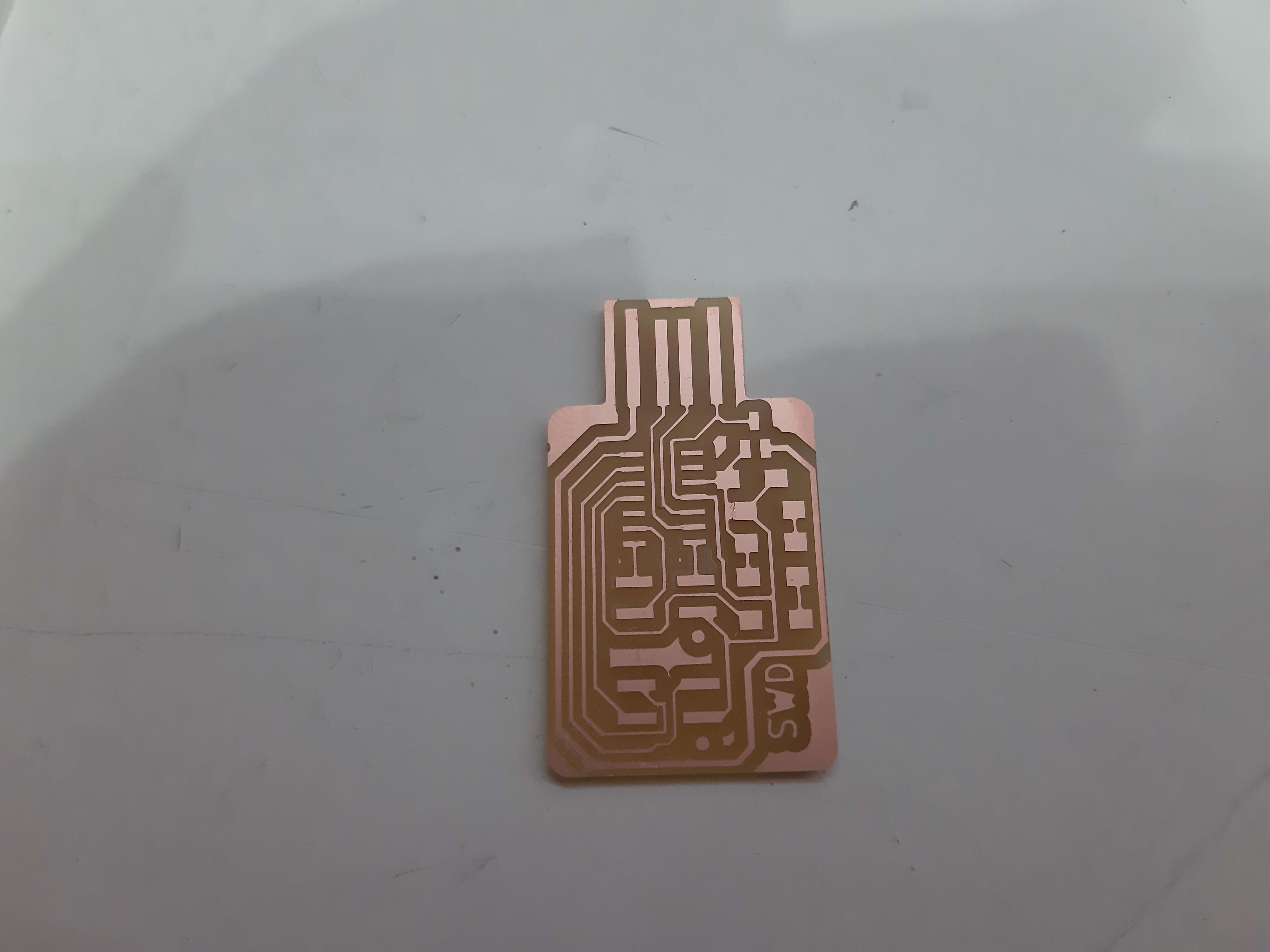
We basically start it from 2 images, png files in particular (for its properties of no loss of resolution), one where all the electrical connections traces we want on our PCB are drawn and the other one define the outline shape of the PCB itself.
So in order to make a PCB you need at least to mill 2 times, typically with two different sizes of mill-tips (one of 1/64 in for traces and the other one of 1/32 for outline).
Obviously the CNC machine we are gonna use to mill, doesn't understand png files, we need to convert those in .rml files (basically these are files instructs the machine which path the tip should follow).
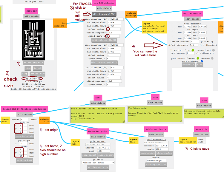
To get the .rml files from a .png we will use the modproject website, with the following specifications:
| CNC Values | Traces | Outline |
|---|---|---|
| DPI | 1000 | 1000 |
| Offset | 4 | 1 |
| Speed | 3 m/s | 0.5 : 1.5 ms |
| Max Deepth | standard | 1.75 |
| Origin | 0,0,0 | 0,0,0 |
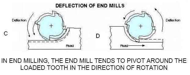
A separate discussion must be made for climb and conventional as they are two ways in which the machine works, I personally have found good result producing all my PCBs with the climb mode, as is shown later on.
The steps to follow are described in the following image:

As I explained in the previous paragraph, you need 2 mill-tips to create a PCB. The setting procedure is roughly the same for both:
Take the copper plate you want to mill and it must be glued to the machine worl-table with double-sided tape. After that you need to install the appropriate mill-tip in the machine.
We can now open the control software and set the origin, that is the point where we want to start the job. (remember that the machine will start mill from the lower left corner of the png image, use it as a reference point). Once the tip is positioned on the desired XY point, we can move to set the Z axis. The situation here is delicate, as it is necessary to unscrew the screw that holds the mill-tip just enough to make the tip touch the copper plate.
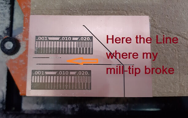
In order for the tip to correctly mill the copper plate, it is reccomended to press LIGHTLY the plate so that when the machine runs, the tip can mill effectively. And I repet it: Very Lightly. My first mistake was indeed to press too hard during the setting. This then caused the tip to break after just a few seconds from the start as I reported in the group assignment repo.
So I had to repeat the process, this time being much more careful. So having the correct Z point found, I screw the tip back on and saved the coordinates on the control software. Then I let the tip rise before starting work.
To start mill, click on Cut button and add your .rml file (delete others files that have been previously done otherwise the machine will repeat them) and finally click on output.
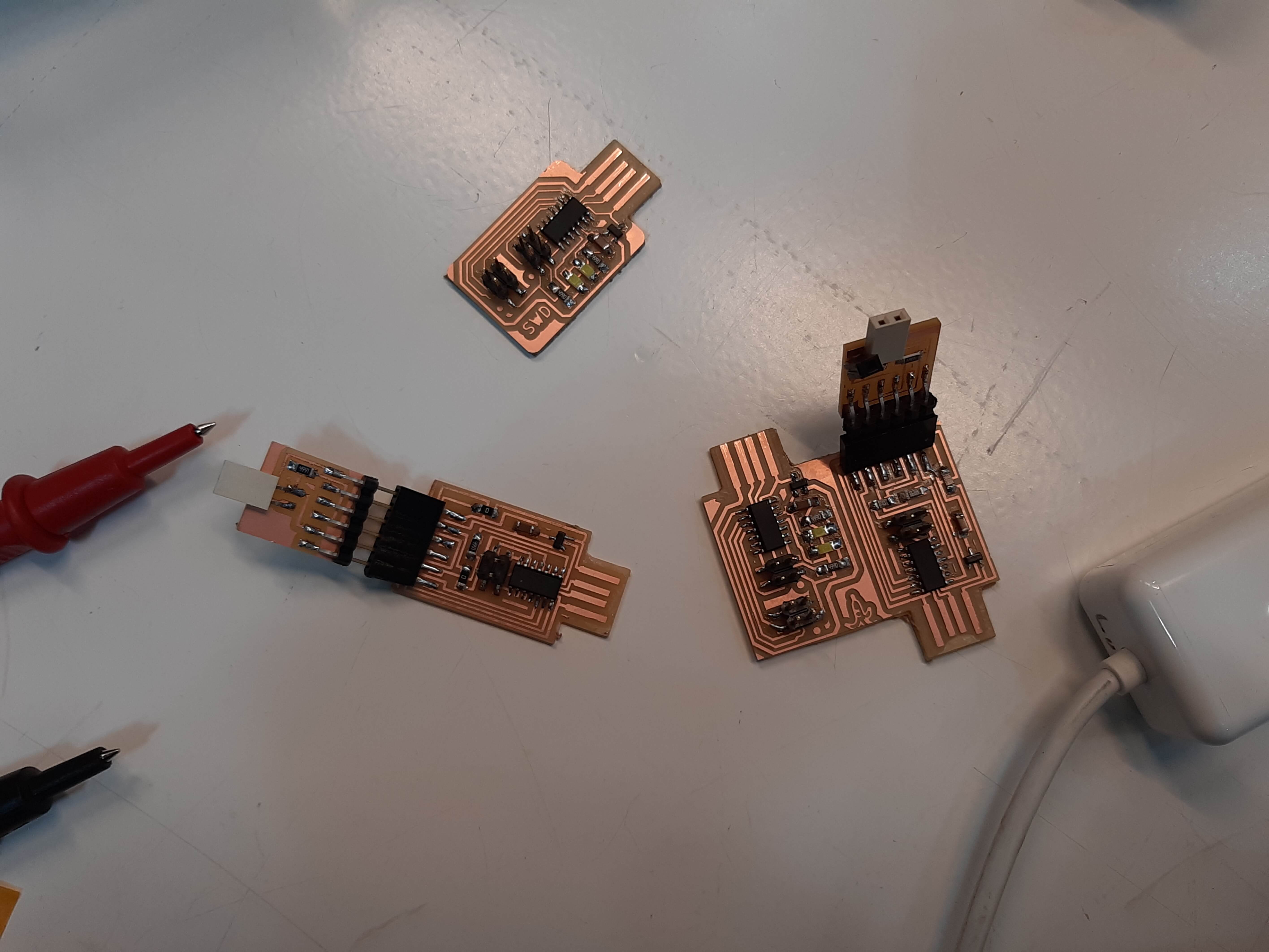
I had so much fun doing the PCBs the I wanted to go next level and try to join (almost) all the boards we have as assigment as one.
But without any competence in PCB design I tried to use Inkscape to modify the png files of the traces and the outline, as I explaned in the week 2 page.
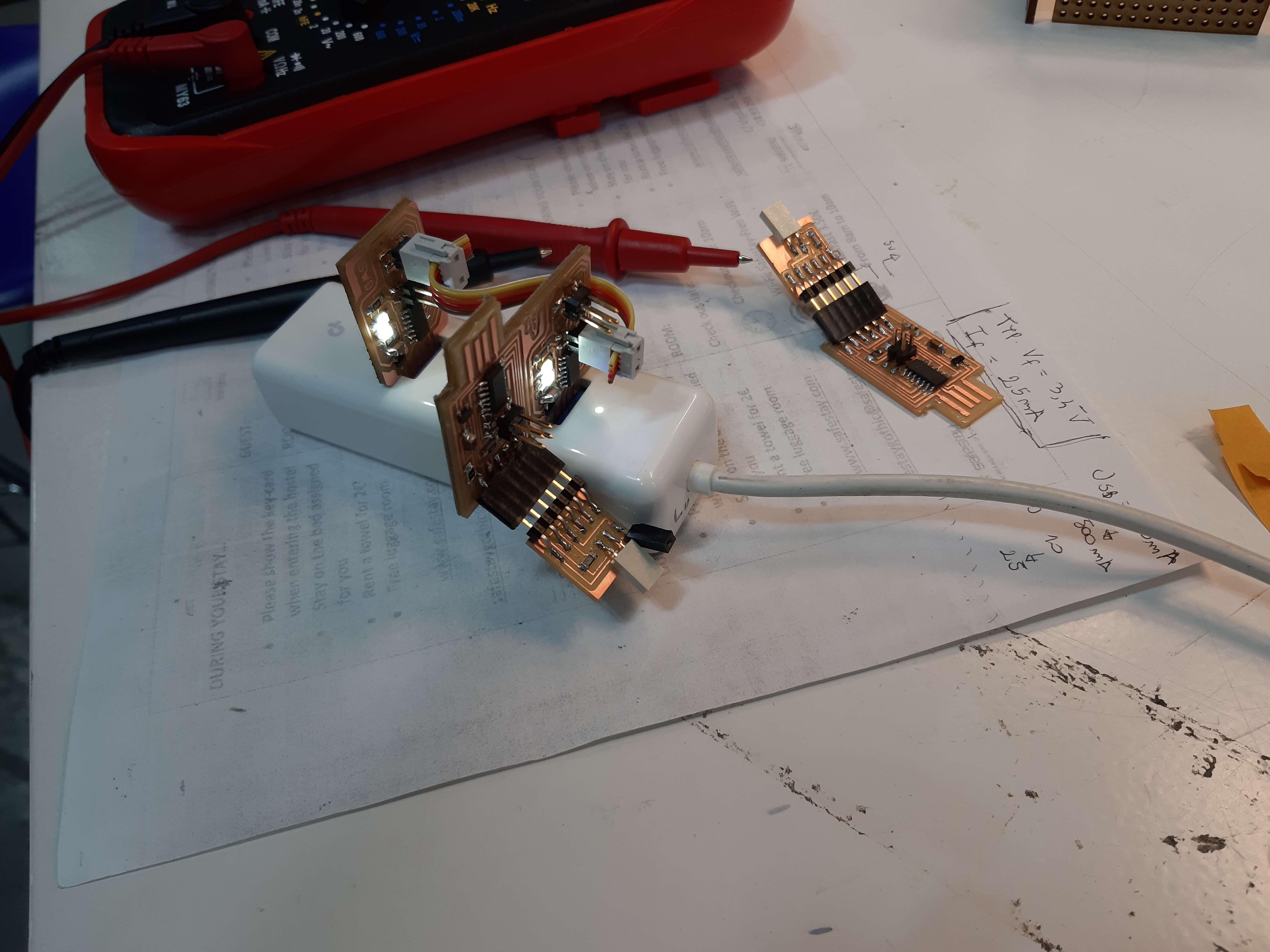
In order to program the ucontrollers I've just followed the guide I found in the fabcloud gitlab page.
In particular, you need to use edbg.exe and a specific binary file (one for the Programmer and another one for the Serial interface)
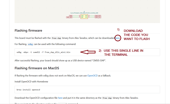

To upload the code it is highly reccomended to use an USB hub to avoid possible problems to the computer USB port in case the PCB causes any short.
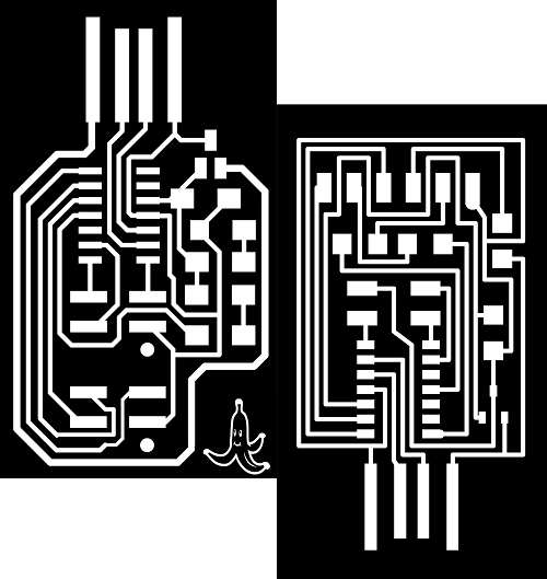
As I explained in Week 2, I merged the Programmer and the Serial Interface in one single PCB, and added a Banana logo to customize my design and in order to be able to use both the device just flipping the board

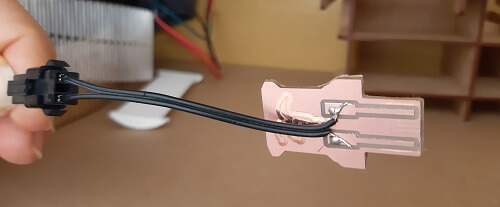
I enjoyed so much the USB connector you can create directly on a PCB that I ended up creating one for my PinHole Glasses, so that I can light up those just connecting to a Computer:

Copyright © 2018 - All Rights Reserved - Domain Name
Template by OS Templates