Useful Links
comments
- Link 1 ✔
- Cut a line to a specific lenght in InkScape ✔
- Link 2 ✔
- Link 3 ✔
other comment
Output Devices means showing the result of a internal processing to the real world, when we speak we are transforming the result of our thought into sound. This week we will do the same using mainly electronics.
My primary idea was to reproduce a bigger version of project that I had already previously created, which is an LED matrix on which I could reproduce some text sent via bluetooth communication or other simple animation.
An LED matrix works in a very interesting way, as it only uses 16 pins for control 64 LEDs, and to program it you must therefore use a form of Multiplexing.
A significant example is given by the following short video in which I have programmed the matrix to have all the LEDs on, and I also programmed the potentiometer to control the velocity of the execution of the code to show how everything really works from the inside.
In fact, by slowing down the execution of the code, you can see that only one LED lights up each time but increasing the velocity makes the whole matrix seem enlightened, this is the Persistence Of Vision (POV) effect, and it is gonna be crucial for my final project.
I then programmed the same matrix to receive some text and display it as scrolling text where the scrolling speed is adjusted by the potentiometer.
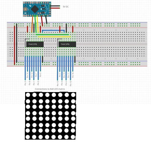
It is also interesting to point out that I do not control the matrix directly with the Arduino as it would require 16 output pins (i.e. the pins of the Matrix itself), but I use two shift registers.
Shift registers are ICs that Serial In - Parallel out shift Register (SIPO) copy link: https://circuitdigest.com/tutorial/what-is-shift-register-types-applications This way I can control the matrix using ONLY 3 pins from the Arduino.
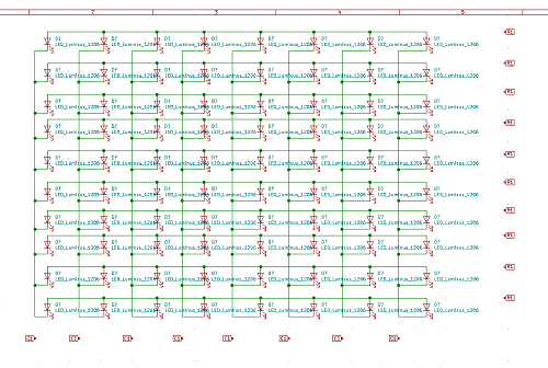
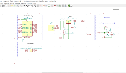
Having said that, I was starting to design my giant LED matrix and here you can see the schematic created on Kicad.
But I then decided to try something new, specifically a new kind of multiplexing suggested by my instructor Josep, the same type he also used in one of his FabAcademy assignments and It is called Charlieplexing.
The idea is to create a Binary Stopwatch.
CharliePlexing is just another form of Multiplexing, basically taking advantage of the property of the LEDs to be able to light up when the POSITIVE current it only passes in one direction (from Anode to Cathode), then the LEDs can be arranged as shown in the figure below.
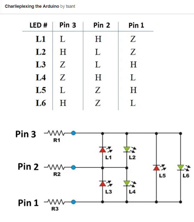
So, for example, if I want to light up LED L1 I will need pin 3 on the HIGH logic level, pin 2 on the LOW logic level and (for completeness) you need to also disable Pin 1 programming it as Input.
With this technique I can therefore control N (N-1) LEDs through N pins of a microcontroller.
And of course, by lighting the LEDs individually at a very high speed, animations can be created through the POV effect, similar to what explained for the 8x8 LED matrix.
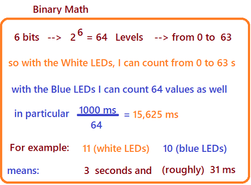
In my case, I wanted to create a stopwatch that counts both seconds and milliseconds, specifically I have set up 6 LEDs for the seconds and other 6 LEDS for the milliseconds, for a total of 12 LEDs controlled by 4 pins.
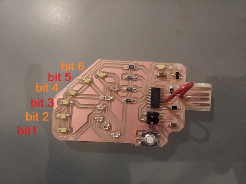
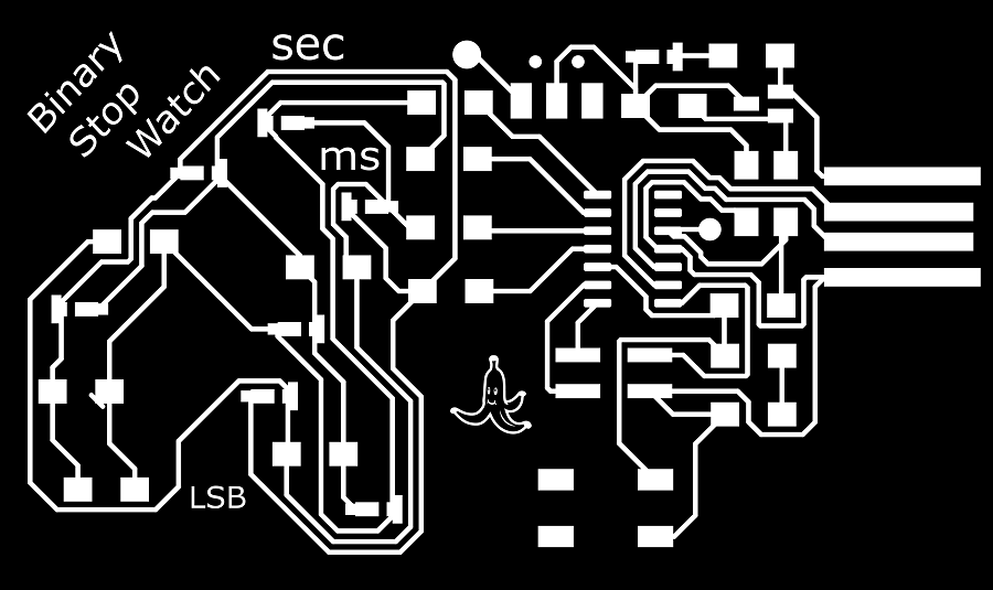
Here's what the finished board looks like, let's see below more details about it:

The board consists of 2 rows of 6 LEDs each, both rows show binary numbers (obviously a lit LED means bit 1 while when it is off the bit is 0).
The least Significant Bits (LSB) are placed on the bottom of the board (for both rows), as indicated in the picture.
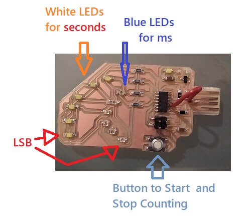
I used white LEDs for seconds and blue LEDs for milliseconds.
At last I added a button for the counting start and stop of the stopwatch.
Now let's explain in detail the code I used to program the device.
I first defined the functions to illuminate the specific LED according to the bit you want, like explained in the theory. In the following image you can see the functions regarding the first 3 bits.
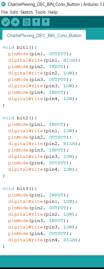
Next I created two functions:
printFullBin: which converts the integer given as an input parameter into a binary number.bitList: which contains all the bit functions described above.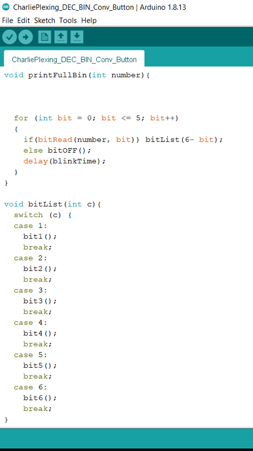
So if for example the decimal number we get, as a result of a counting operation by the stopwatch, is 6, we already know that the corresponding binary will be: 110.
As a result, the printFullBin function will convert 6 to the number 000110.
The same function will now evaluate each digit of the binary number, if the digit is 0 no LEDs will be on, if instead it is 1 then the bitx() function will be activated in bitList corresponding to the position of the digit itself.
So for the number 000110, the function will only calls the functions bit2() and bit3().
Summarizing once again what happens for each digit of the binary number:
| digit 1 | 0 | All LEDs off |
|---|---|---|
| digit 2 | 1 | only LED 2 on and others off |
| digit 3 | 1 | only LED 2 on and others off |
| digit 4 | 0 | All LEDs off |
| digit 5 | 0 | All LEDs off |
| digit 6 | 0 | All LEDs off |
from here the cycle starts all over again.
The cycle is so fast (blinkTime is set to 1ms) that LEDs 2 and 3 appear light up at the same time.
And finally we have the main control code of the stopwatch:
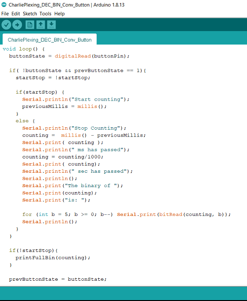
Above I defined the button and the output operations in the Serial Monitor, hence when the button is pressed, the stopwatch starts counting by increasing the variable "counting".
When the button is pressed again, the stopwatch stops, displaying on the Serial Monitor (if the device is connected to the computer) the calculated value both in Decimal and Binary, and passing the same to the FullPrintBin function explained above in order to light up the specific LEDs.
Below there is a video of the device working (counting only the seconds):
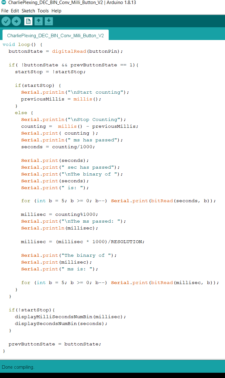
Once the count in seconds has been successfully tested, add the milliseconds was quite simple. Basically the code is almost the same, with the addition of a few more mathematical operations (Note that the milliseconds counting has a resolution of approximately 31ms as explained in this section).
Here is the main part of the updated code.
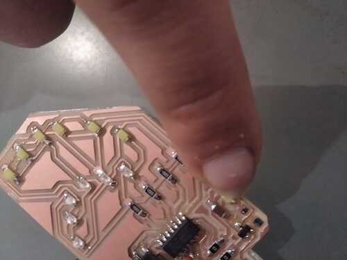
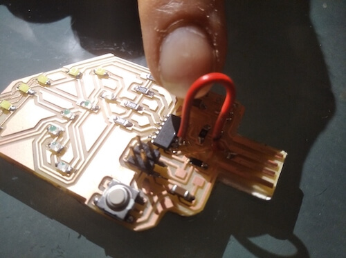
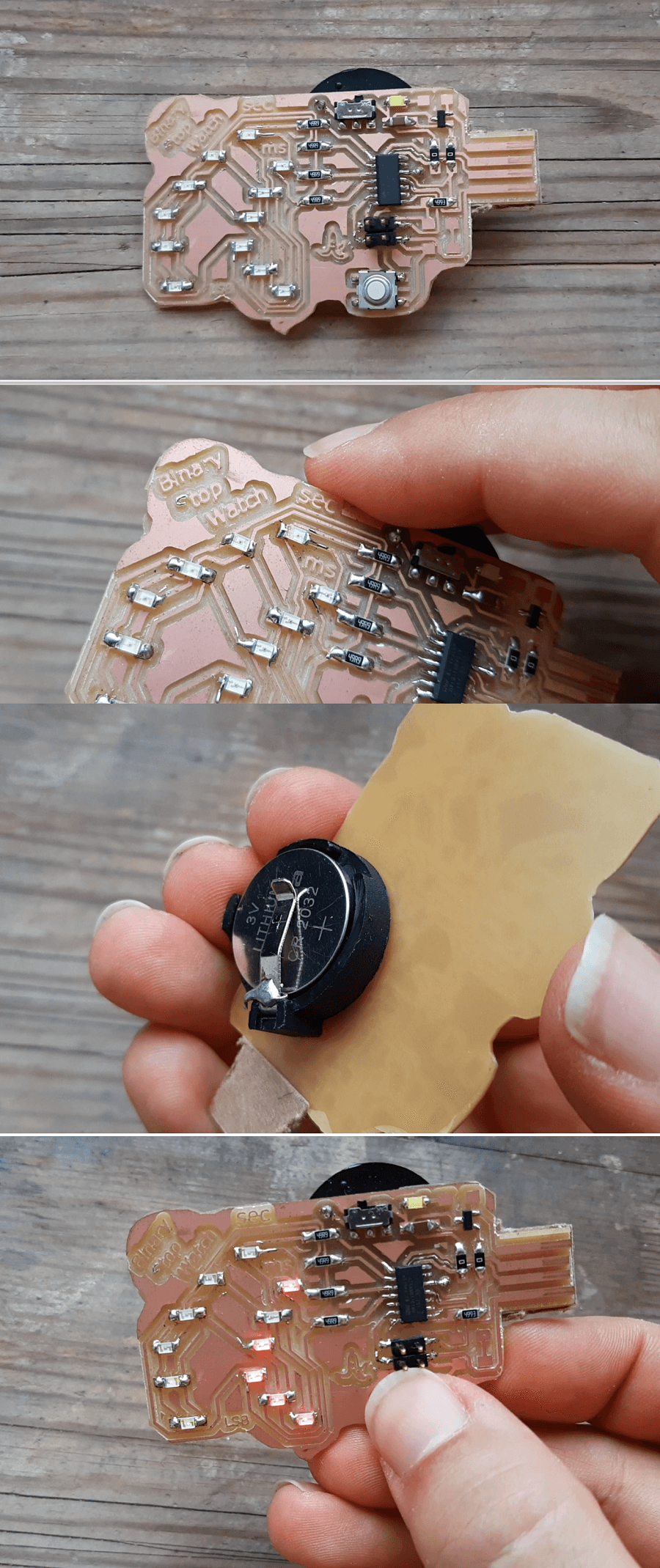
I then upgraded the device making it portable, adding a Coin battery and a switch, the upgrade was necessary because reading numbers in binary is already a torture if I wouldn't have made it portable at least it would have been a completely useless device.
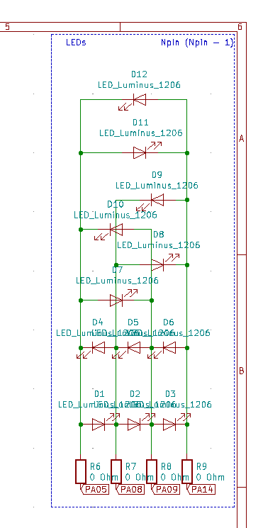
Here is the schematic of the updated device:
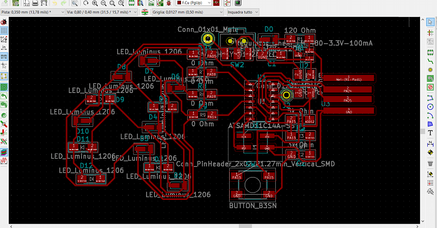
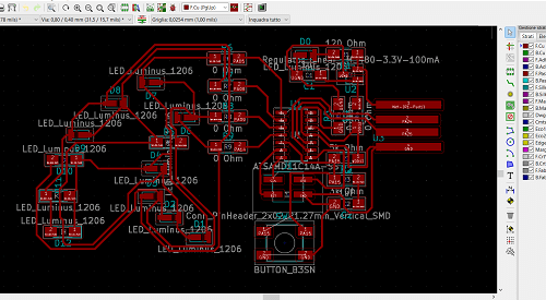
And here the improved Layout!
Even if I preferred al lot more the white and blue LEDs colors, for this version, I opted for the red and green LEDs as they have lower power consumption and therefore suitable for using it with a battery.
Final note, the final version of the stopwatch program is very voluminous for the SAMD11C, in fact, as you can see in the following image, it uses almost all of the microcontroller memory.
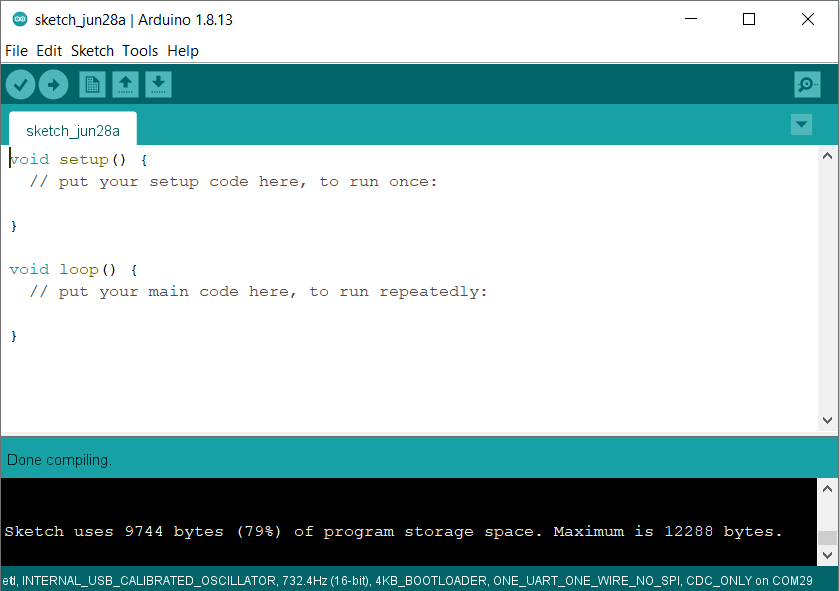
That's because there are a series of libraries uploaded to the SAMD11C each time you upload a program code you wrote with arduino IDE.
These libraries are needed for you to program the microcontroller using directly the Arduino IDE, but only they occupy 79% of the SAMD11C's entire memory.
To overcome this problem, we can save some space by removing the bootloader from the memory of the SAMD11C.
This way we save about 25% of memory that we can use to load a more substantial code at the cost, however, of a little inconvenience in loading codes.
That's because without the bootloader we could no longer upload programs to the SAMD11C directly by clicking the "Upload Code" button in the Arduino IDE, instead we need to firstly convert the code in a .bin and then upload it via a programmer.
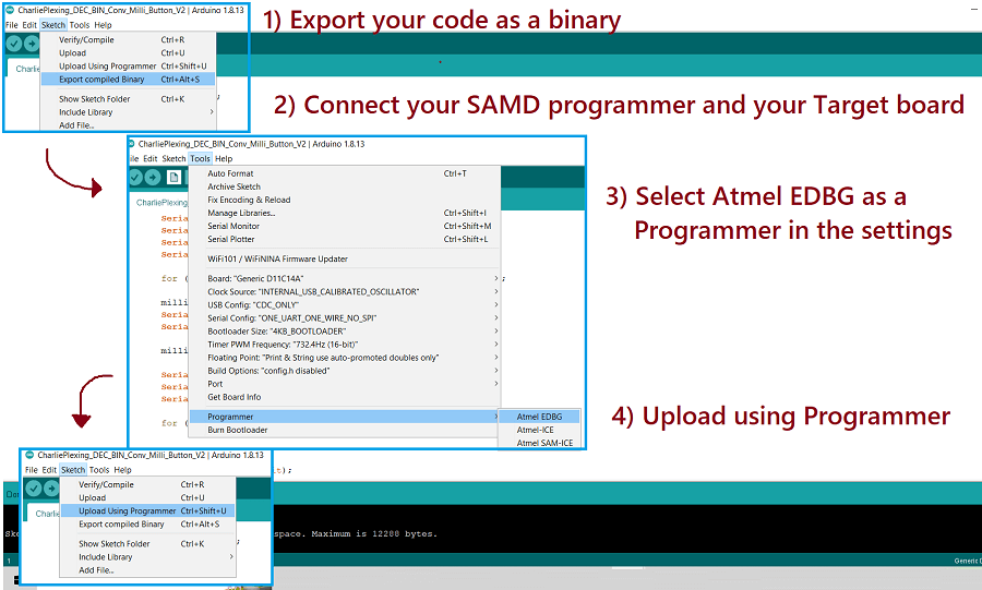
Although the whole procedure is certainly longer, it can still be done very easily through the arduino IDE.
Warning: The following part it is not completed yet. I am writing the minimum to get
      the assignment approved and in July I would be available to finish it.
As a second project for this week I'd like to make a Boost Converter.
A Boost Converter is a device that takes a constant voltage input and give a higher constant value as an output.
Specifically, I want to create a variable Boost Converter, where the voltage output value is controllable through a potentiometer.
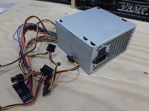
This idea came to me when I took a PSU from the junkyard near my FabLab.
A PSU gives power to different parts of a desktop computer (HD, DVD/CD player, ..) which therefore has several voltage outputs at fixed values. In particular:
| Red | 5V | |
|---|---|---|
| Yellow | 12V | |
| Orange | 3.3V | |
| Blue | -12V | |
| Purple | 5V | active even when the unit is off |
| Black | GND | |
| Green | Connected to GND turns the unit on |
This Power Supply was very useful for me to test my LED matrix at home (link page), but having only fixed values of output voltage is very limited in its use

So the idea is to simply use the boost converter attach it to the 5V of the Power Supply as an input, and have an Output voltage with a range that goes from 6V to 10V, this way you can use a whole range of intermediate voltages that could come in handy.
The electronic scheme of a boost converter is not very complicated, the operation it can be explained very simply in the following way.
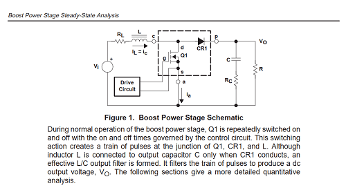
When the transistor is active, creating a short circuit, it will make pass a large amount of current into the inductor. This will then begin to be charged with electromagnetic energy.

Then when the transistor turns off, creating an open circuit, all of it the huge amount of stored energy from the inductor will have to go somewhere. It then opens the path via the diode and will go towards the capacitor which it will begin to charge up.
By repeating the cycle several times, it will eventually happen that the capacitor will be charged as an higher voltage than that one applied as input.
The microcontroller role is to decide (through a feedback system, created simply with a voltage divider) the timing to correctly activate or deactivate the transistor depending if the output is demanding more or less power in order to mantain a constant output voltage value.
To properly design the device I referred to the following document, published by Texas Instruments.

Specifically, I extrapolated the equations that would have been useful for the design.
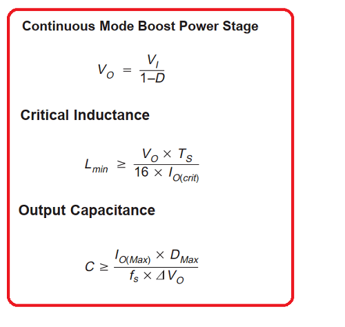
I changed one value of the first equation because the one given from the document was an approximation, I derivated mathematically that the more precise equation would be:
| Vi | Input voltage 5V |
|---|---|
| Vo Max | Output voltage 10V |
| D | duty Cicle ___ |
| Dmax | Max Duty Cicle (Vo = 10V) |
| fs | PWM frequency |
| Ts | PWM period |
| IoMax | Output current max |
| Io (crit) | Output current min |
| Vo | ARipple voltage Output |
Once we know a little bit more about the thory, let's decide what type of components to use, I started with the inductor.
Unfortunately there weren't many in the FabLab, so I took the one I thought should be the most suitable value for my purpose considering its size and number of windings.
The problem was then how measure its inductance. Unfortunately in the FabLab we do not have automatic inductance measuring instruments, I therefore equipped myself this way:
Having a function generator, and a small pocket oscilloscope (not the best in terms of accuracy but better than nothing). The procedure is then to create an RL filter with the inductor to be measured and a resistor 50 Ohm as shown in the figure:
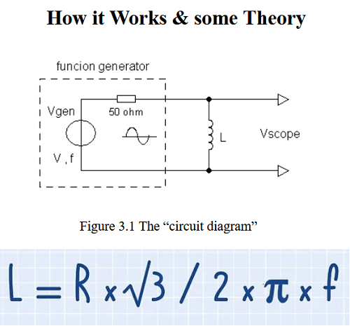
Set a sine wave with a certain voltage value (I chose 1V) and measure the output wave across the inductor with the oscilloscope.
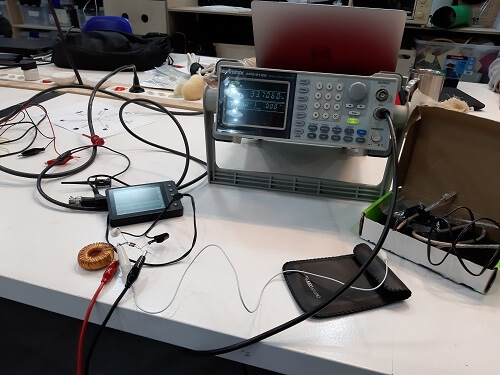
Then vary the wave frequency of the function generator until the wave in output at the ends of the inductor has an amplitude value equal to half that of the input (hence 0,5V).
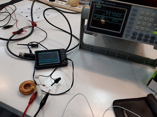
Finally, the frequency value found must be entered in the following formula.
The inductance value found in my case was therefore :::::
Having found the inductance value, I was therefore able to obtain all the other parameters, thanks to the previous formulas.
Specifically: Excel sheet.
Note that as the frequency of the PWM signal I have chosen the value ::::
It is not a value chosen randomly, but rather chosen from one of those available from the microcontroller SAMD11C.
In fact, to change the frequency values of the PWM signal generated by the SAMD11C just go in the specific menu of the arduino IDE.
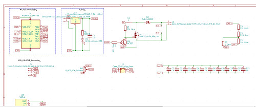
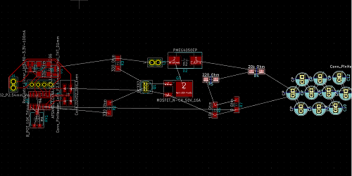
Once I got all the values, I proceeded to create the circuit diagram on Kicad.
Here is the schematic of the complete PCB.
Burning the bootloader.
Unfortunately, however, the same device did not pass the smoke test when I then connected it to the power supply.
In this period I do not have the material time to investigate what the problem was, I hope to have more time in the future and resume the project to complete it.
Copyright © 2018 - All Rights Reserved - Domain Name
Template by OS Templates