Application and interfaces, this week we will deal with how to interface with different types of applications the hardware devices we familiarized with over the past few weeks.
In my case, I completed this assignment during a break I spent in Italy with my family. Specifically, I created an App for Smartphone with MIT INVENTOR 2 to control remotely the garage door of the house because the original device failed.
The Garage Opener I made
In this page I am gonna explain the whole "repairing" process of the garage door that I went through,
it took longer than I thought but was totally worth it because very educative.
What happened?
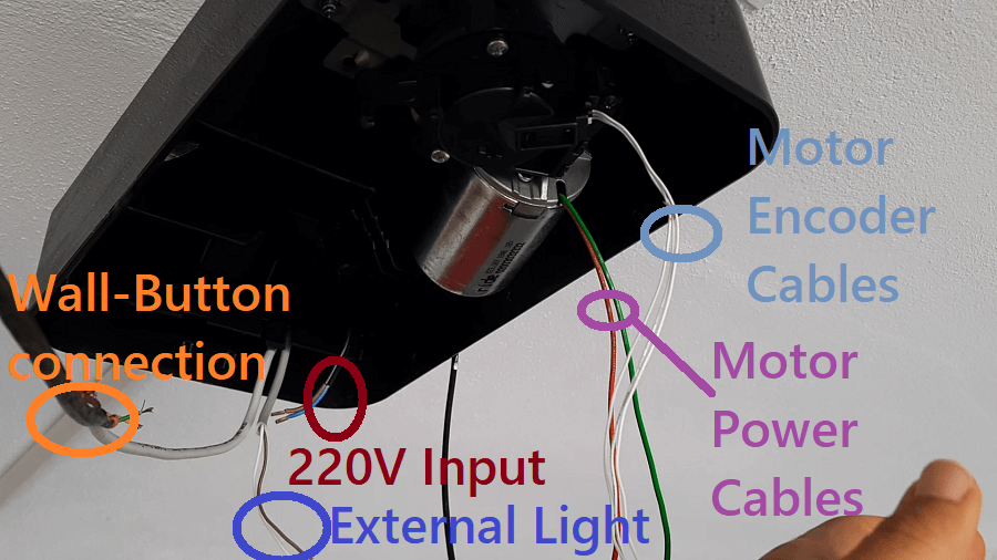
What is left of the Garage Opener device
Let's start from the beginning, the electronic garage opening mechanism broke due to an overload of
current. My father in my absence asked in an electronic reparing center to fix it but they weren't able to.
He then contacted the manufacturer who would have made him pay a
consistent price for the replacement of all the equipment (including the working parts).
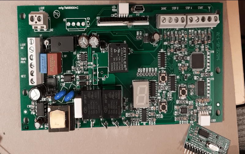
The original broken electronic board
So I offered my help to repair it. In reality I have no real repairing skills,
I just know enough about electronics to "simply" make a new device that could
replace the broken one. The idea is to use an ESP32 which has the integrated bluetooth connection so that
everything could be controlled remotely.
Garage First Test
The only healthy part of the whole apparatus was the internal light and the DC motor that could perfectly let the garage door slide when turn ON.
I tested the motor with a 18V transformer with a maximum of 4A output, previously by looking its serial number and the resulting datasheet
of the engine (which is not public, so I only found the information on the merchant's site).
DC Motor commercial website
The motor worked very well in the first Test, I could therefore raise or lower the garage door simply by changing the polarity of the voltage applied to the motor input.
Motor Encoder
Applying direct and reverse voltage to the motor gives you the power to control the direction but not to control the amount of revolution you need to accurately open or close the garage door.
hat is something I needed to solve otherwise it would have given enormous problems! In fact the whole structure is not provided whith
endstops switches so whenever the motor is moving it would not realize if the garage door would have touched the ground or the upside, potenzially destroying everything.
As I expected, the DC motor was equipped with another set of 3 wire turns out to be an Encoder. >An encoder is nothing more than a device used to read the revolutions or fractions of it of a motor.
The problem, not having an official datasheet, now remained how to "reverse engineering" this 3-wire Encoder.
So after a quite long internet research I came across to a detailed web page guide with video tutorial included,
in which are explained the different types of encoders and how to test them.
The process of "reverse engineer" and studying the encoder was really interesting and satisfing. In order to do that you obviously first need to know what it's in the inside.
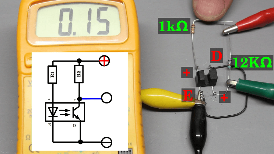
How to test a 3 wire Encoder with a Multimeter
Basically an encoder is just an optical sensor composed of a LED and a Phototransistor, those are placed
next to eachother in a way that the phototransistor can sense whenever the LED lights up, and in between them
there is a wheel (attached to the rotor of the Motor so they can rotating at the same speed ) with specific
holes in it. So when there is a hole in between, the photoresistor senses the LED and turn ON outputting a
LOW digital Signal while when there is no hole, the phototransistor turns OFF, outputting an HIGH signal.
To test the pins of the Encoder I used a multimeter, the 5V output of my Arduino and an High value Resistor to avoid frying any components in the inside.
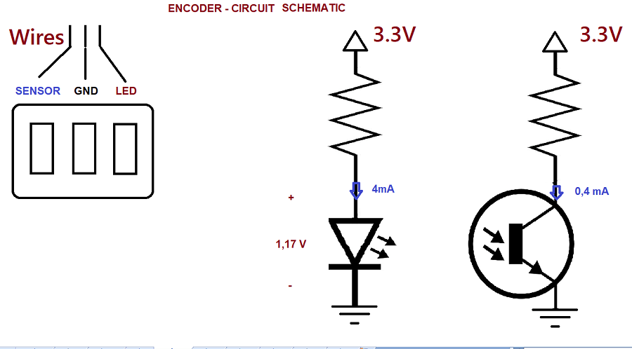
Once everything is properly tested, I finalize with the following electrical configuration using a resistor
of about 460 ohm for the LED and one of about 8Kohm as a pull-Up for the phototransistor.
Schematic of the Encoder
This encoder emits a series of pulses as the motor spins, it doesn't tell the direction of the engine tho as more complex ones.
Once I was certain that the engine worked in all its features, I began to schematize the whole device.
Design of my Garage Door Opener
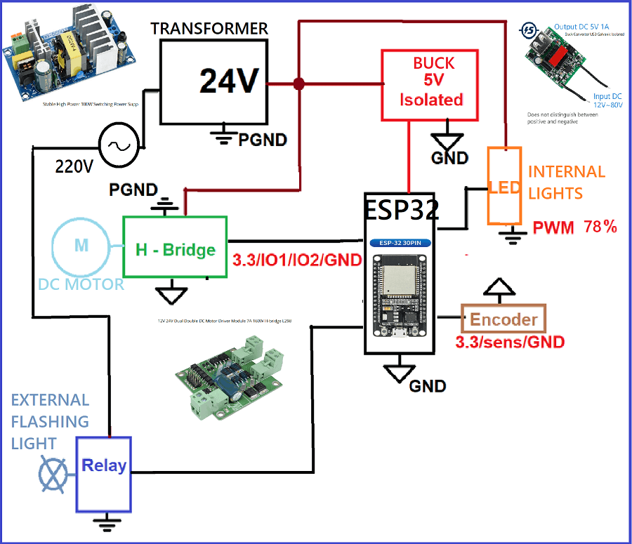
Here's the list of the components I took:
ESP32: The microcontroller in charge of managing the whole device.
Switching Transformer: Unfortunately, as the original transformer was burnt, I needed something
that could convert the alternating voltage into a continuous one but still providing adequate power
for the motor movement. Specifically, it generates an output of 24V with a max current of 6A
H-bridge: A high-power H-bridge to control motor directions.
ISOLATED Buck converter:5V Buck converter to power the microcontroller that I would have used
(ESP32), isolated because Bridge H required the control device not to share the same
power voltage ground.
Relay: To be able to control the outside flashing light and turn it On when the garage door is moving,
this light has its own transformer inside Testing it works with 220Veff.
Transistor: To be able to control the internal light that already illuminates very well at 12V, I was able to
observe when inspecting the circuit that there was a capacitor in parallel to the input.
This made me guess that it was suitable for being controlled with a PWM signal, and indeed
I was able to use a 24V output from the Switching transformer with a Duty Cicle PWM signal of 78%.
Other minor electronic components for compliting the overall circuit.
This is the electronic schematic:
Schematic of the whole device
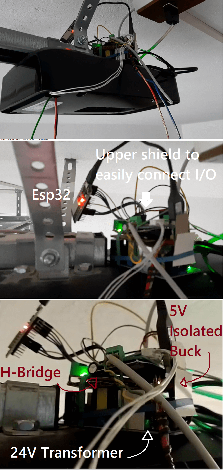
This is how the whole device is temporary mounted:
Yeah, it's hold up with elastic bands and cardboards
ESP32 for motor control
We arrived to one of the most important parts of the whole process, which is to configure the microcontroller
ESP32 in order to control the whole device, specifically programmed it for the following tasks.
1): Scan for any active BLE (bluetooth Low Energy) devices in the proximities.
2): In case the scan finds the mobile phone on which the application is installed, connect to it.
3): Once the connection is made, ESP32 will update the user with the application in what position it is
the garage door (Open, Closed or intermediate position).
4): The moment the button on the application or the physical button on the wall is pressed, the system
will have to perform the following actions.
4a): The garage door opens or closes depending on which one
action has done previously, then the system remembers what action the garage has performed and in
if the button is pressed, the door will perform the opposite operation.
Obviously this action is achieved by sending a specific control signal with PWM to bridge H.
4b): the system must record the number of revolutions of the
motor in order to prevent the door from exceeding the physical limits of the entire structure. The calculated laps
from fully closed to open are ------
4c): furthermore the system must switch on the relay which
consequently it will turn on the external flashing light and must also control the transistor with a PWM signal
to switch on the internal courtesy light.
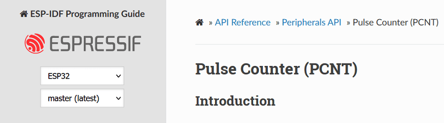
ESP32 Pulse Counter
EspressIf guide
Among the most interesting and most useful things that I came across in using the ESP32, was discovering
the integrated Pulse Counter function.
The pulse counter sensor allows you to count the number of pulses and the frequency of a signal on any pin.
On the ESP32, this sensor is even highly accurate because it’s using the hardware pulse counter peripheral
on the ESP32!! However, due to the use of the pulse counter peripheral, a maximum of 8 channels can be used.
The PCNT (Pulse Counter) module is designed to count the number of rising and/or falling edges of input signals.
The ESP32 contains multiple pulse counter units in the module. 1 Each unit is in effect an independent counter
with multiple channels, where each channel can increment/decrement the counter on a rising/falling edge.
Furthermore, each channel can be configured separately.
PCNT channels can react to signals of edge type and level type, however for simple applications, detecting the
edge signal is usually sufficient. PCNT channels can be configured react to both pulse edges (i.e., rising and
falling edge), and can be configured to increase, decrease or do nothing to the unit’s counter on each edge. The
level signal is the so-called control signal, which is used to control the counting mode of the edge signals that
are attached to the same channel. By combining the usage of both edge and level signals, a PCNT unit can act as a
quadrature decoder.
Besides that, PCNT unit is equipped with a separate glitch filter, which is helpful to remove noise from the signal.
PCNT on Arduino IDE
Unfortunately, digging into the official documentation, it was kinda difficult to find straightforward examples
of how controll the PCNT peripheral through the Arduino IDE.
I digged a lot into the web searching for help, but It is something it is not yet very well known, that's why
I am writing this assignments with such details, because I think I am sharing useful informations here.
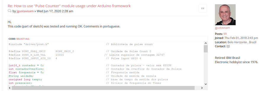
Anyway I only found a resource that showed how to use it with the Arduino IDE, it was not even explained but
just the code was displayed. I found it in the EspressIf forum by the Brasilian user jgustavoam. I really
want to credit him for the helpful postes he made.
jgustavoam and his helpful code
I explained the code in the Appendix A (link)
Once I had the starting point code I edited it to suit my device.
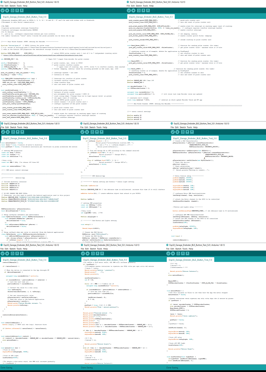
Code Explanation
I am not gonna explain the whole code here because it's very long, I will focus on the Bluetooth communication
aspect, but the rest of the explanation is in the Appendix B (link)
Screenshots of the entire code, one of the longest I've ever relized for the Arduino
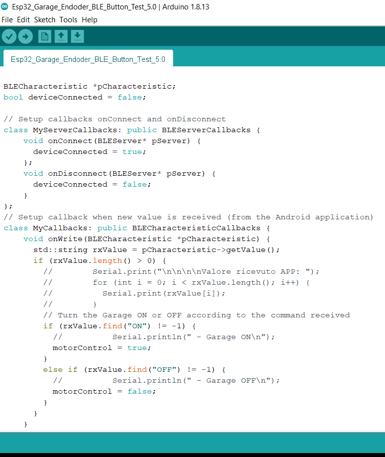
So first of all we define some Callbacks functions, those functions get activated when some action on the Smartphone
application is done (ie button pressed).
Callbacks functions
Specifically I defined the callback function
about the Bluetooth Connection/Disconnection when the Connection/Disconnection
button is pressed in the App.
And I define a callback function that is activated when the button Start/Stop [the garage door] is pressed.
When the Start button in pressed the App will send a string "ON" to the ESP32 that will set the boolean
variable motorControl to True.
Instead when the Stop button is pressed the App will send a String "OFF" and motorControl will be set to False.
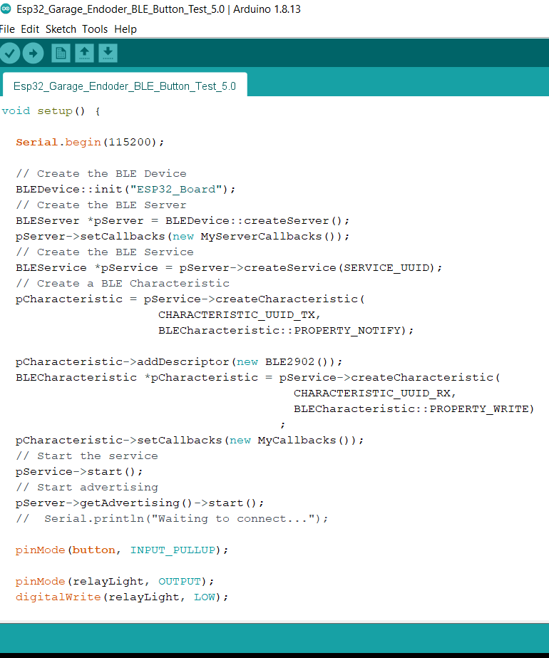
Bluetooth Setup functions
Above, you can see the Setup instructions for the BLE.
Basically the code is to firstly Create the BLE Device, then the BLE Server, the Service and the Characteristic
and finally Start the BLE service.
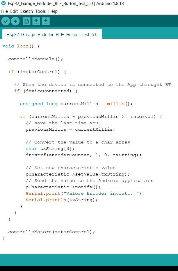
Now let's jump directly to the loop function:
loop function
Basically, it starts with the function controlloManuale() that checks if the pushbutton on the wall is pressed
(the pushbutton on the wall acts like the start/stop button in the App).
Then if the variable "motorControl" is false (meaning the the garage is stopped) and if
the App is connected throught bluetooth a timer start and every "interval" (set as 2 sec) time
the info about the amount of the motor spins is converted in a string and sent to the App so that the user
can see that.
At the end, we have controlloMotore(). A function that takes the motorControll bool variable as input paramenter,
if it's true it turns ON the motor (opening or closing the garage) and turn ON the outside and inside light while
if it's false it turns OFF everything.
Design the APP using MIT INVENTOR
Finally we arrive to the main part of this assignment, that is designing a sort of interface meant to control
one or more electronic hardwares.
As I said before I am gonna use an App created by Mit App Inventor.
MIT App Inventor 2
This web application has 2 different layouts:
The Designer view is to design the front-end of the App
The Blocks view is to design the back-end of the App
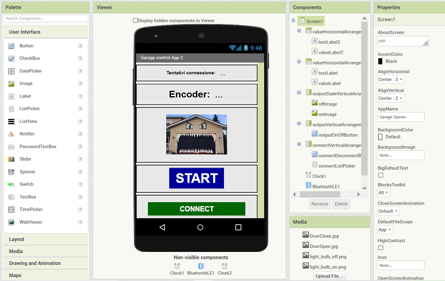
The Designer view
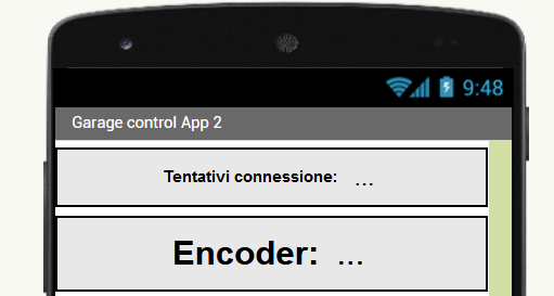
I design the aesthetic of the app in a very simple way. As you can see I added at the beginning 2
TextLabels associated with ValueLabels:
the Front-end
The first one is to count the number of automatic connection attempts from the App to the Esp32 before a connection
is enstablished.
The second is to count the number of the motor revolutions (from the Encoder Sensor) counted by the Esp32.
Close up of Text and Value Labels
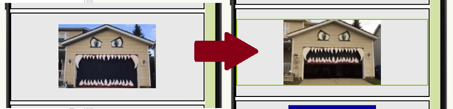
Then I added an Image that changes whenever the Garage Door is opening or closing
the 2 switching Pics of the App
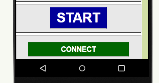
Finally I added 2 button boxes that change their text when pressed.
The first one is to Start/Stop moving the Garage Door
The last one will display if the App is connected to the Esp32 and give you the possibility to disconnect it
when pressed.
Close-up of the 2 buttons
There are then Non-visible components like the Bluetooth Low Energy fuctionality and 2 Timers (Clock 1 and 2),
the latter are needed to set an interval time (500 ms) of the Connection attempts and to check if a new Encoder value
from the Esp32 is sent.
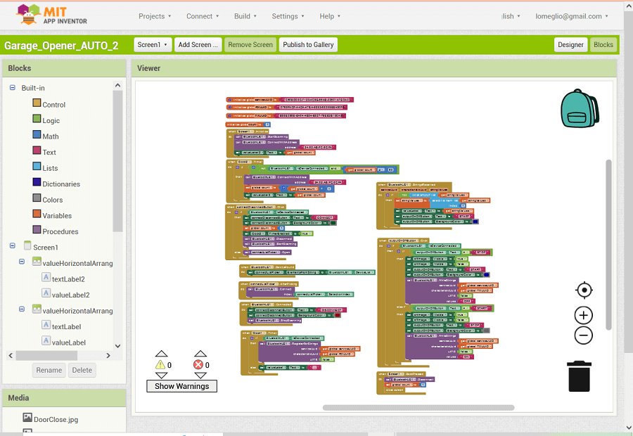
the Block view
The interesting part of this Web application is that you do not need a deeply understanding in programming to
create an App because the back-end is makeble with blocks, similar to Scratch Coding
the whole block coding
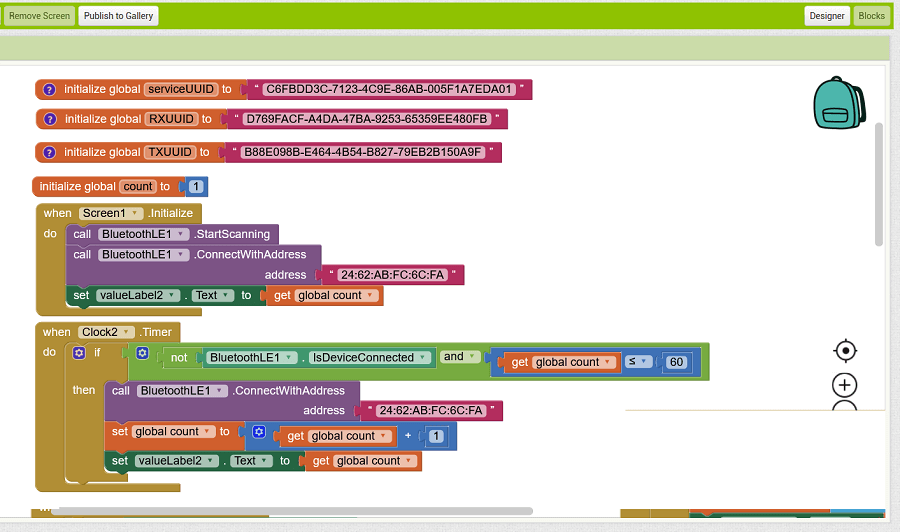
So at the beginning there are some initialization processes, and after the App is opened it starts scanning
to search the specific Address of my Esp32.
center>first block
If the connection is not established from
the start, the App will then try every Clock2 time (that is 500ms) repeatedly connect for 60 attempts.
center>second block
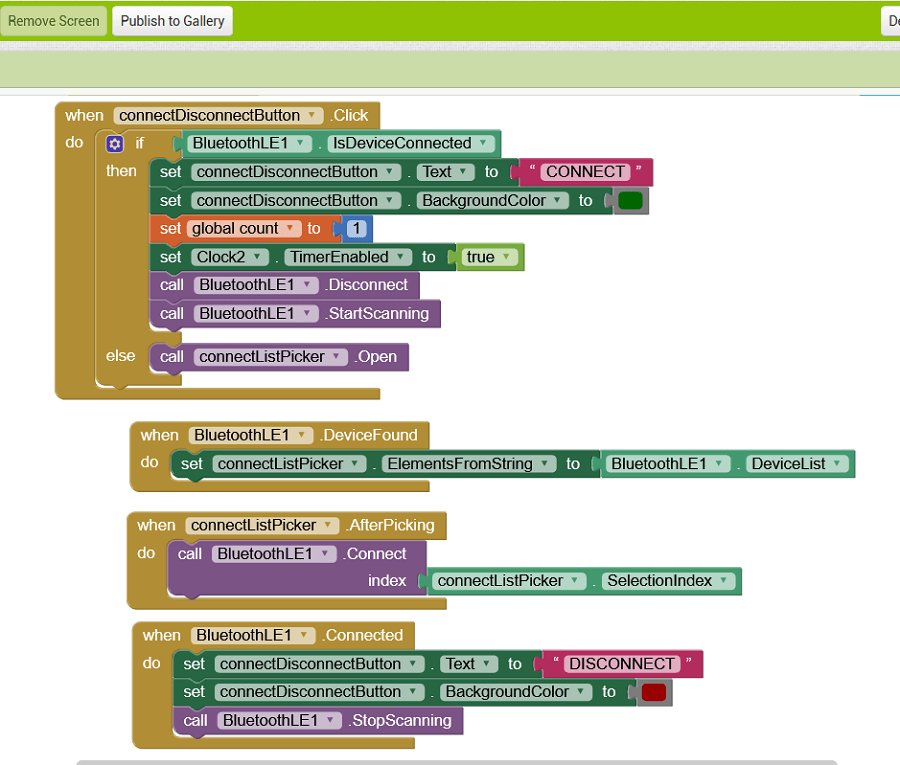
In the next blocks (especially in the first one and the last one of the above image) I programmed the Connect/
Disconnect button of the App. Basically if the device is already connected (meaning the botton will display
"Disconnect") and you press it, the application will change the writing in the botton to "Connect" and it will
try again to establish the connection for other 60 attempts.
When the device establish the connection the button will change to Disconnect and the device will stop scanning.
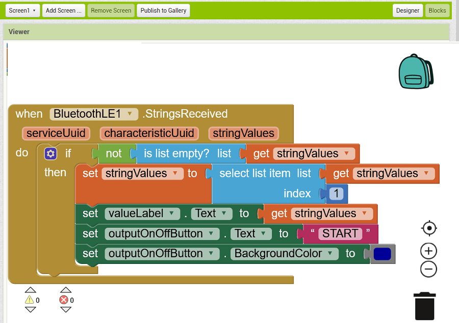
center>third block
The block above is to visualize the Encoder Value (stringValue) passed by the Esp32. You can see that after
showing the value I programmed to change the Start/Stop garage door button writing into "Start" because I programmed
the Esp32 to send the value only after the garage door is stopped.
center>forth block
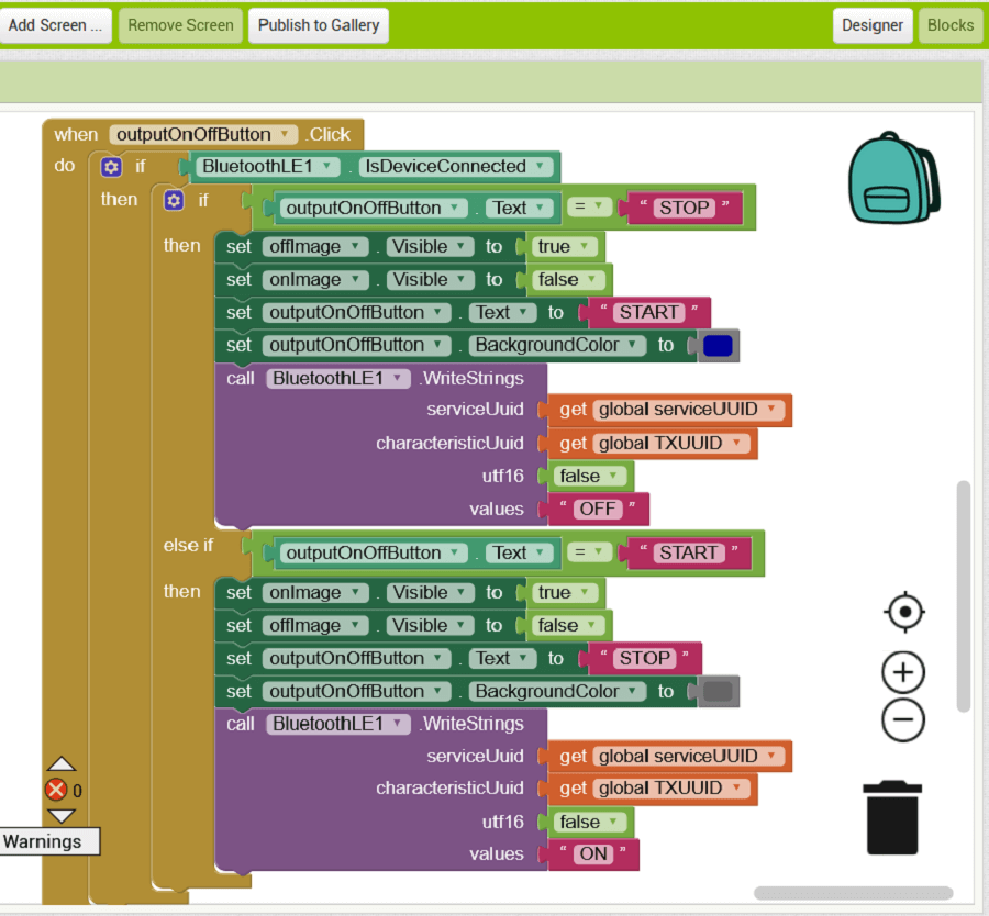
Then there is the block that deals with the management of the Start / Stop button. Hence when the button is pressed
(and the device is connected) if the button was set to "Stop" then change its writing to "Start", consequently it changes
the image displayed by the App and finally send the string "OFF" to The Esp32 to stop the garage door.
Similar actions are performed if the button is pressed again, but this time the string sent is "ON" to activate the movement of the door.
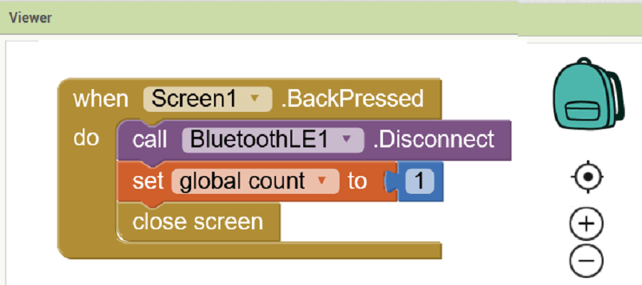
final block
Finally we have the closing block that simply disconnects the bluetooth connection and resets the
"connection attempts counter" variable when the App is closed.
Appendix A
This will be complited in July. Right now I am writing the minimum to pass the local evaluation.
Appendix B
This will be complited in July. Right now I am writing the minimum to pass the local evaluation.