Useful Links
comments
other comment
I dedicated most of the available time to create the electronics, the code and test the whole thing. So let's start from the beginning.
I originally took inspiration from an Adafruit project, the same linked in my Final Project idea page. The problem with that is the use of specific library for a their specific microcontroller, I was not sure if it would have worked right away with an Arduino Uno type so I decided to look around and find something else.
I came across to this Instructble. Where this girl created a POV wand and The project is really good in its simplicity, . The alterneting movement she does is exactly the same as the pendulum I do with my juggling.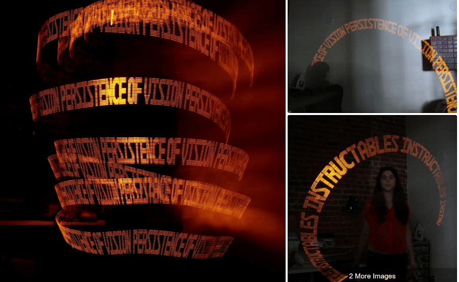
There is an issue with that tho, depending on the direction of the movement you can see the writing either in the right orientation or flipped. This is something I obviously needed to improve in my final project.
Before doing that, let's understand the its code.
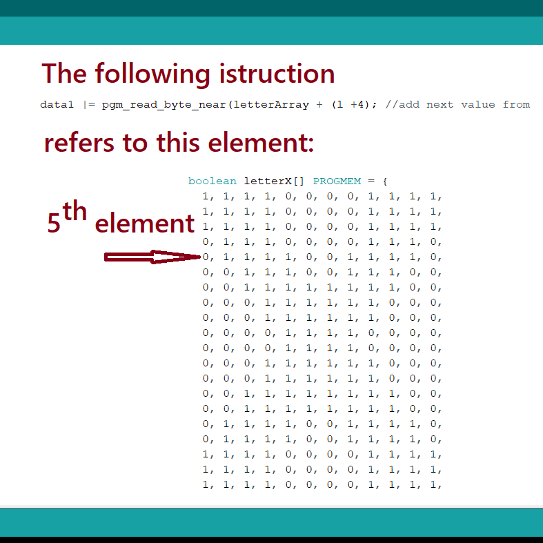
The symbols and letters displayed are based on booleans Array, like the one showed in the pic.
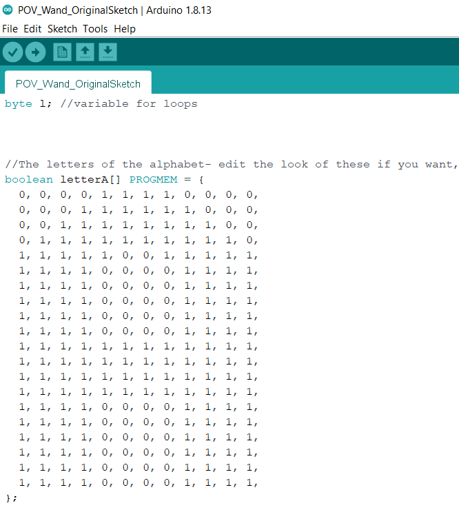
I repeat, it's an ARRAY even if it's arranged as a Matrix, where the number of raws is 20 like the number of LEDs of the device and the number of column is the width of the letter.
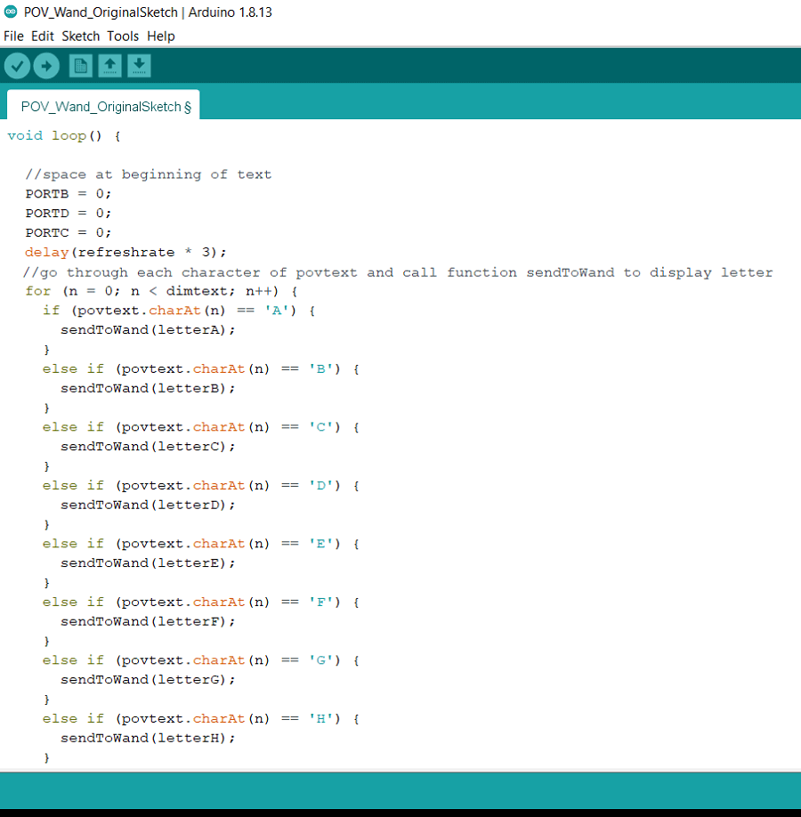
pThe next function is the core of the entire program, it is based on bitwise operation and port manipulation.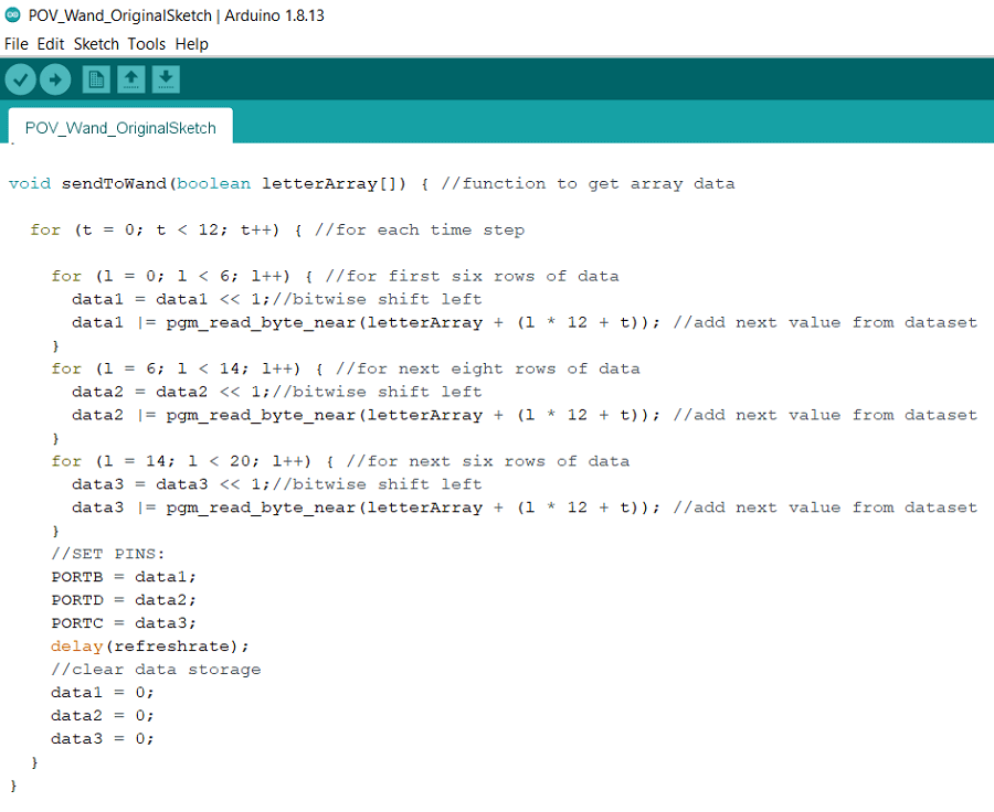
So the funtion get one of the letter array as an input parameter.
Then a FOR cicle start and it lasts as much as the width of the "Matrix" Symbol (12 iteractions in this case).
Basically the FOR cicle goes each time through one column of the "Matrix" and lights up the corresponding LED if the element is a 1.
I will describe an example to explain the whole procedure step by step.
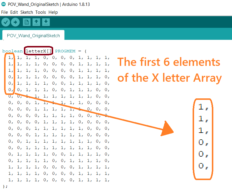
Let's take the first 6 symbols of the Letter X first column that is 111000.
And before continuing you need to keep in mind that the pgm_read_byte_near(letterArray + (l * 12 + t))
funtion takes the POINTER of the letterArray Array as an input, meaning in our case the first element of
the letter X (that is 1).
So to understand better if I would write pgm_read_byte_near(letterArray + 4) it means I am considering
the 5th symbol of the letter array.
So, back to the whole code explanation, the variable data1 is inizialized to 0.
The same variable undergoes a series of operations through the bitwise shiftleft data1 = data1 << 1 and the bitwise nor operation pgm_read_byte_near(letterArray + (l * 12 + t)) I explained above.
Here I created a table to summarize the changes in data1 variable during the the first 6 symbols of the Letter X first column (111000)
| FOR cicle | data1 value | data1 value after bitwise shiftleft | pgm_read_byte_near(letterArray + (l * 12 + t)) VALUE | data1 value after bitwise nor |
|---|---|---|---|---|
| 1 | 0 | 0 | 1 | 0+1=1 |
| 2 (t=0, l=1) | 1 | 10 | 1 | 10 + 1 = 11 |
| 3 (t=0, l=2) | 11 | 110 | 1 | 110 + 1 = 111 |
| 4 (t=0 , l=3) | 111 | 1110 | 0 | 1110 + 0 = 1110 |
| 5 (t=0 , l=4) | 1110 | 11100 | 0 | 11100 + 0 = 11100 |
| 6 (t=0 , l=5) | 11100 | 111000 | 0 | 111000 + 0 = 111000 |
At the end of the inner for cicle the PORTB = data1 instruction is run to light up all
the LEDs connected to the PORT B (meaning from pin 13 to pin 8).
Then the variable data1 is reset in order to start another cicle for the next column.
The loop function is very easy compared to the previous one.
Shortly, it start by creating some space before the text begins, just keeping the LEDs turned OFF for
refreshrate * 3 millisec (refreshrate is set as 1)
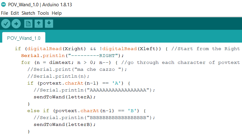
Then a for cicle starts (like we didn't have enought before) and goes through each letter of the string variable "povtext" so that the sendToWand function can be called individually.
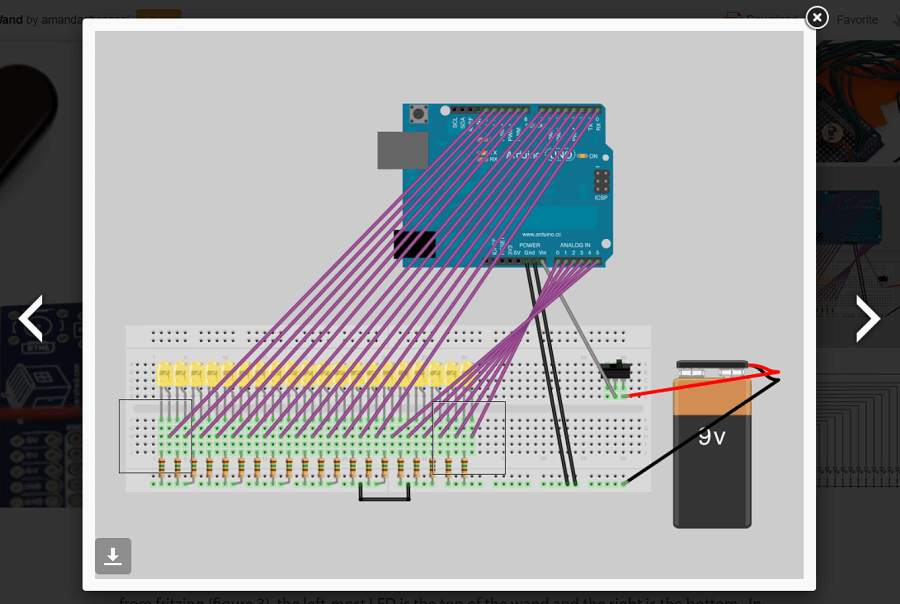
Having the instructble as a reference, you can see that the hardware it's very simply. Basically and Arduino UNO with an LED connected to every pin (both digital and analog are used as Output).
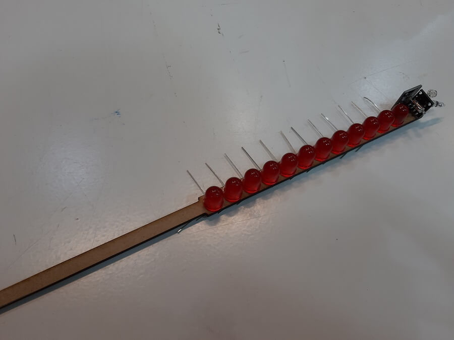
so my first very prototype to test the working principle of the device was made by a laser-cutting a piece of MDEF (more on the laser cutted page) to place 12 LEDs (I reduced the amount from the original project) and solder their end pins with jumper wires.
I then changed a litle bit the code, reducing to 12 the raws of the "Matrix" letters and program it to just display an A. This was the result:
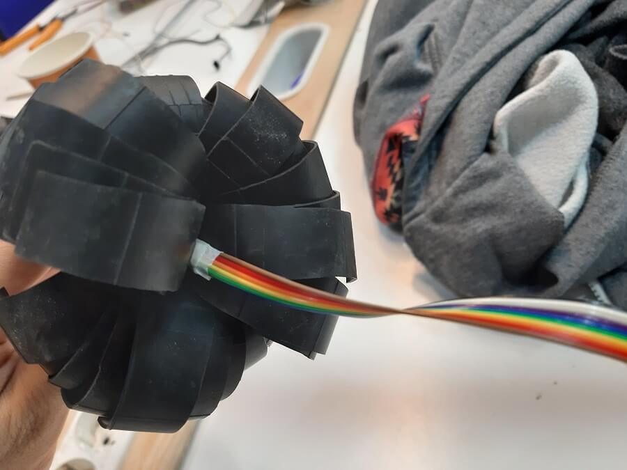
As you have seen from the previous video, the cables mess was unbearble so I proceded to improve that part. I started design the LED holder, considering I would have also put the Tilt-sensors.

The purpose of the tilt-sensors is to detect the changes in the orientation of the main stick.
There are 2 tilt-switches place orthogonally to the main stick axes and also simmetrically to each other, to detect when the main stick hits the right and left position. I called them the X-Axes tilt switch.
Could I have used just one? Yes, maybe but I prefered to be redundant considering the amount of data receiving from those sensors are minimal.
Basically, when I detect a 1 from the right switch and a 0 from the left switch I will know the main stick is in the right position and viceversa.
Then there is a last tilt-switch place parallel to the main stick axes to detect rotation, I am just taking advantage of the centrifugal Force in a rotation.
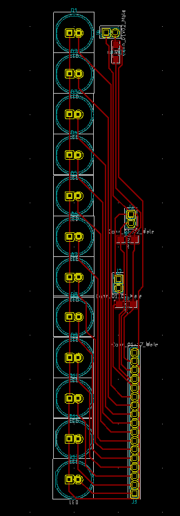
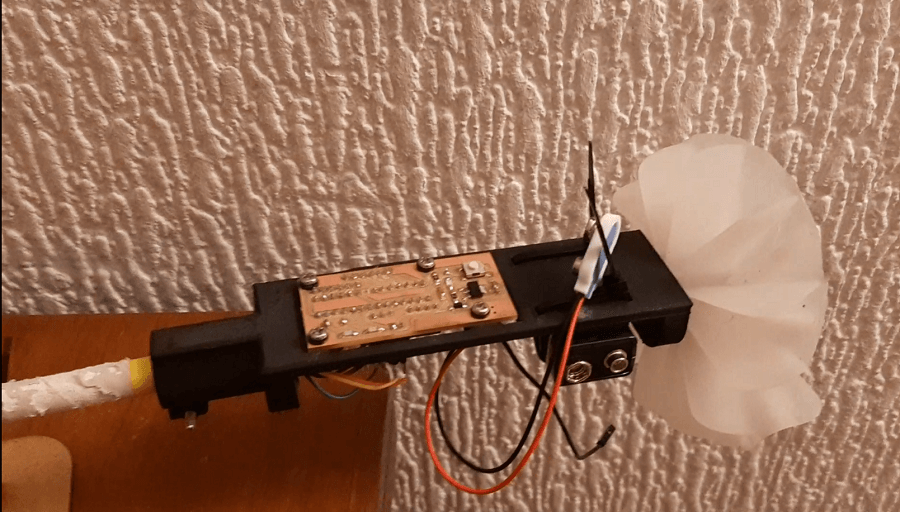
Finally I worked on the cable managing, the idea is to have the LEDs holder on one side of the pipe and the Brain board on the other side, so I fit all the wires inside the main pipe in order to connect every side to each other.
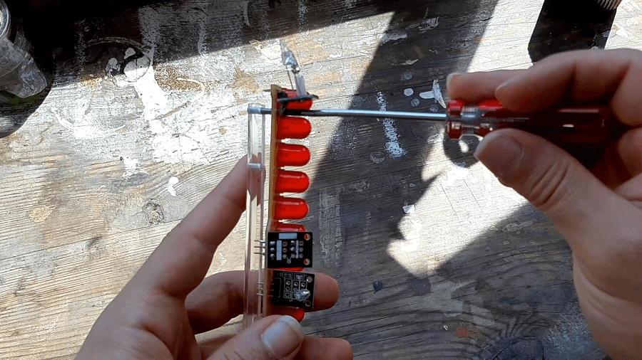
I then laser-cutted an acrylic shape to hold the whole circuit (more on the laser cutted page) . I design it with a "tail" to fit inside the main pipe and together with the wires they created enought pressure to hold it very tight even while I swing it.
Once I had the hardware set, I started changing the code suiting the tilt-sensors.
I focused about displaying asymmetrical writings during a swinging movement of the flower stick, so basically the code modification are made regarding the x-Axes tilt-switches.
Once you understand all the operations behind the code, it is not a big deal to change it as you please. In my case I doubled the sendToWand() function in a way that when the main stick hits the left position the code will start displaying letters as the original code would but on the right position (sensed by the tilt-switches) I programmed to display the letters starting on the left position of the "matrix". Shortly to just see the text accordly of the orientation of the flower-stick.
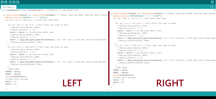
Obviously, when the flower stick is coming from the right position it is not enought to just display the single letters accordly, you also need to display the whole text starting from the last letter.
That's why I also double the function in the loop cicle, where it read the string you want to display starting from the last character and passing all the letter one by one to the previous funciont sendToWand().
This is the final result, where you can see the attempt to display the asymmetrical word FAB.
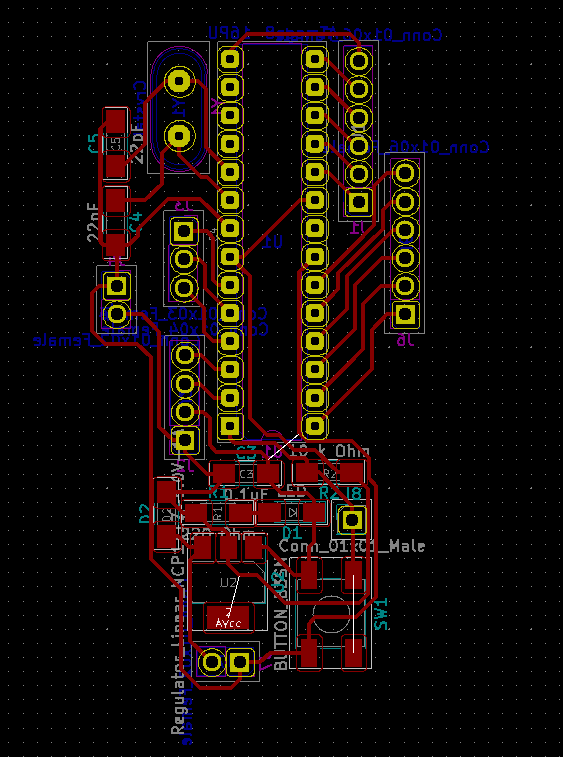
On the other side, I made a brain board with an ATmega8, using the same concepts explained in Week 6.
It happened that after milling the brain board I didn't realize there were some holes missing, and I had already took out the board from the CNC, hence losing the origin.
So what I did, was just design the model of the missing hole, putting again the board in the CNC and accurately set the origin to align the mill-bit for the holes.
After that I prayed for good luck

And It was a success!
Copyright © 2018 - All Rights Reserved - Domain Name
Template by OS Templates