Useful Links
comments
- Raster Vs Vector ✔
- Ideas for Creatives Lamps ✔
- link3 ✔
other comment
2D/3D modeling is the main topic of this week.
I planned to arrive in Barcelona in time for being present for this lesson but I had to postpone my flight (again).. I am not sure if the fate is trying to suggest me something.
Anyway I already have a little experience of 3D modeling (Better saying at least I know what is about). Principally using Tinkercad, a free website. I used it mostly to modeling simple geometry and other minor things. I post some examples of my creations, which I then 3D printed.
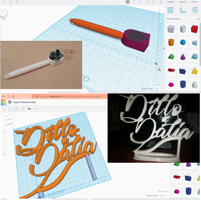
Now it's time to step up and get to another level
During the local FabLab class, I was introduced about Blender, Rhino and Fusion. I was attracted by the former and the last one, but unfortunately Blender is not the best to design mechanical part, so I decided to start practicing Fusion because I think it'll be more useful for my future assignments and the final project. Although it is not open source.
That's why I will try free alternative like FreeCad and OpenCad, as soon as I can.
Since I didn't know how to start modeling one of my potential Final Project Ideas, I started googling some Tutorials (as always I think it'll start every week) to understand how to get what I want.
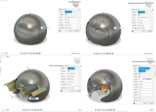
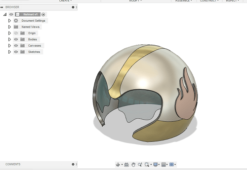
As first exercise I modeled an helmet from an cut sphere and start getting really amazed by a CAD software capabilities!
As second exercise I wanted to level up and use the parametric feature.
The parametric design eliminates the need for a user to constantly redraw a design every time one of the design's dimensions change with out forcing to go back into your model history and change the sizes manually.
In Fusion you can add and change the parameters under the MODIFY menu.
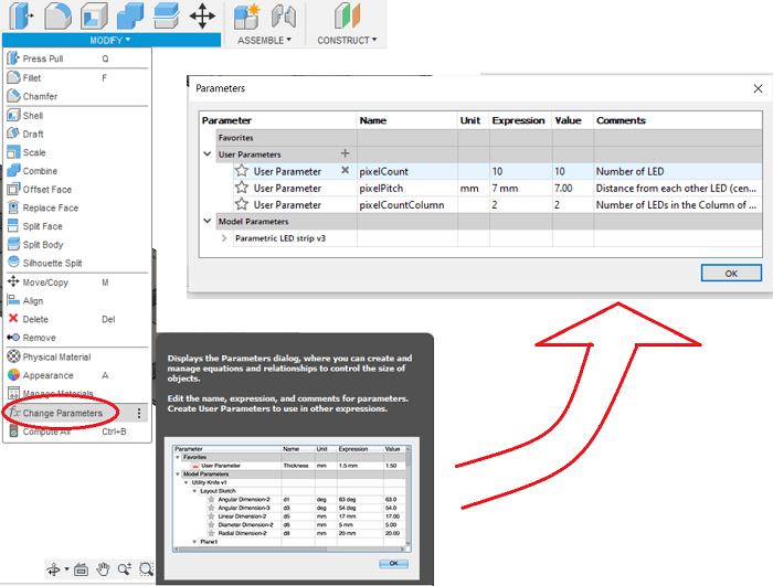
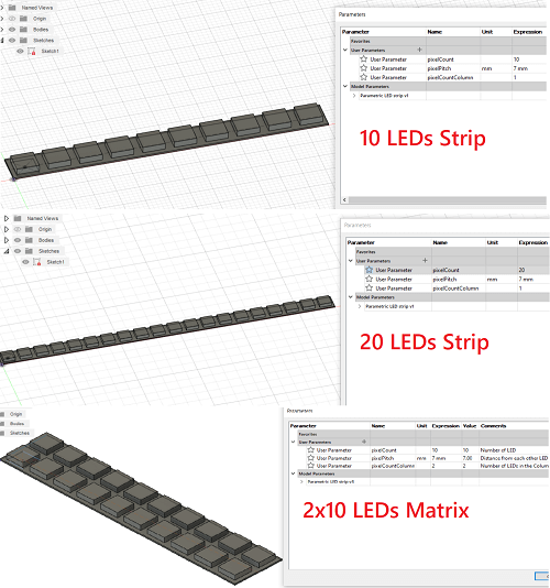
I designed a LED strip which I could very easly change its paramenter and also let it become a Matrix LED, like the one I think I will use in one of my final project:
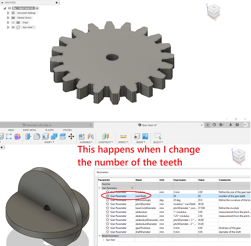
My confident start arise about the CAD but that didn't last too long. Indeed I wanted to parametrically model a spur gear from scratch but changing the number of teeth let the model crash. Maybe I setted some wrong costrain, I still have to figure it out.
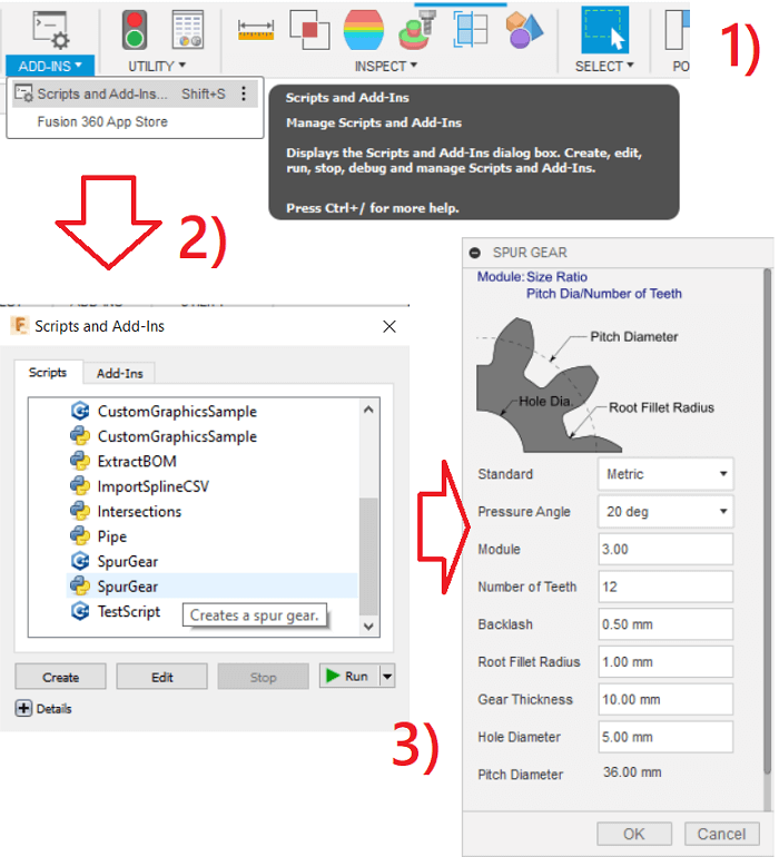
Thank goodness, I discovered a really useful feature, indeed I could automatically import a spur gear because Fusion has Add-Ins about that where you can set the parameters you want. The library is under the TOOLS menu
With all the power of imported spur gears I proceded to create an animation with them. The most frustrating part was creating a compontent for every single piece of the model. That's because whenever I created a new component I didn't realize I had to chooce the parent folder othewise you end up setting every component under the other one folder, like I did. Creating annoiyng problems at the end.
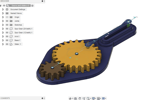
Finally I managed to move the gear and let all the other components connected moving along.
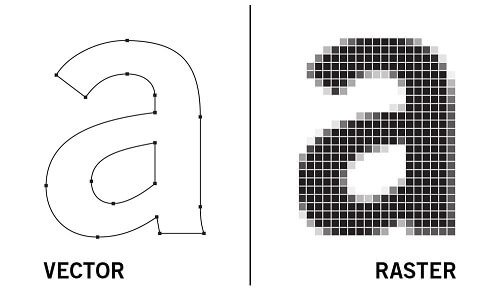
Among the types of 2D CAD software it is worth highlight the differences: We have indeed 2 types: Rasted and Vector.
Raster images, also known as bitmaps, are comprised of individual pixels of color. Each color pixel contributes to the overall image. Raster images might be compared to pointillist paintings, which are composed with a series of individually-colored dots of paint. The pixels in a raster image work in the same manner, which provides for rich details and pixel-by-pixel editing.
Unlike raster graphics, vector graphics are made up of paths, each with a mathematical formula (vector) that tells the path how it is shaped and what color it is bordered with or filled by. Since mathematical formulas dictate how the image is rendered, vector images retain their appearance regardless of size. They can be scaled infinitely.
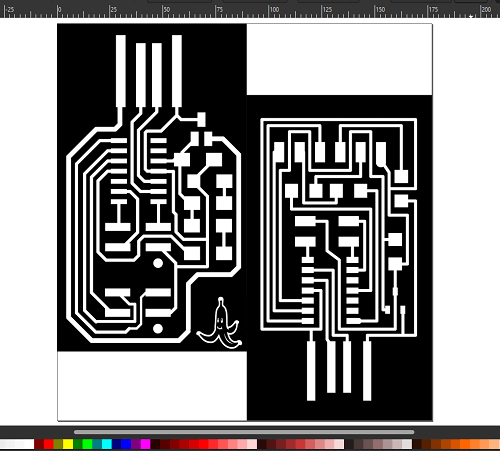
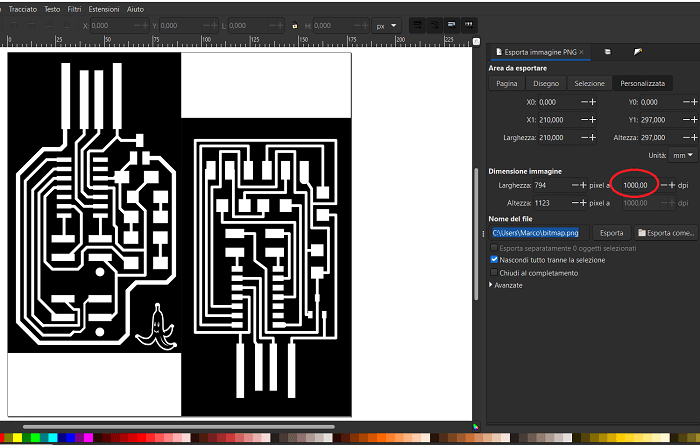
I took advantage of the electronic production week to complete the assignment of week 2 about designing on a 2D CADs. In particular I used this program to edit the png files of the Programmer and Serial interface we need to mill as assignment. My idea was to merge the two boards and obtain an extra cool compact one. Click to see the result reported in week 4.
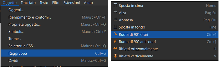
Basically I imported the images I wanted to merge, I rotated of 180° the second one, using the the practical snap function of the software to bring the two images closer together in one appropriate point. Then I selected Group to completely merge both files.
As you can see in the above pic, I added a logo to customize the PCB, the logo was initially black on a white background, so I used: Invert Color option in the Filter menu to get the negative.
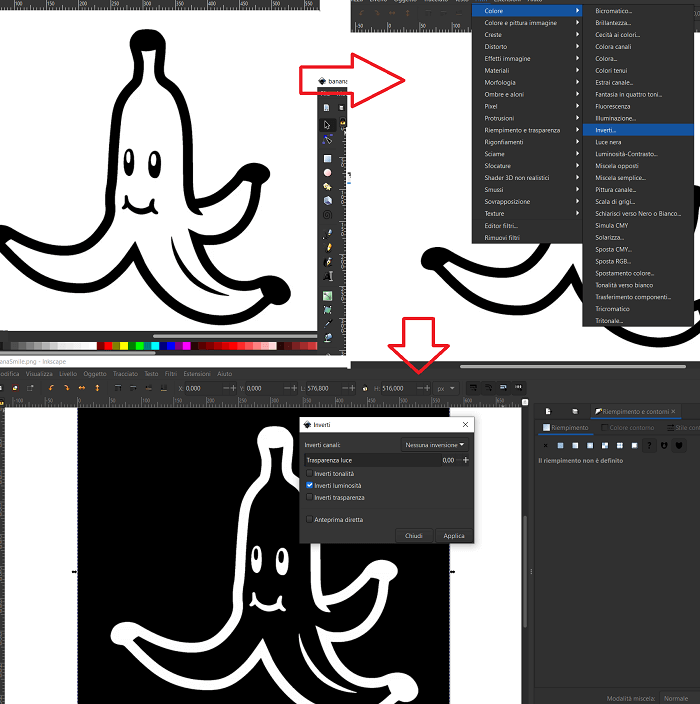
I then repeated the same with the outline file, and finally I exported everything as png file.
it is very important to set dpi as 1000 otherwise the resolution and consequently the dimentions will be affected when you mill, and you don't want that.
Copyright © 2018 - All Rights Reserved - Domain Name
Template by OS Templates