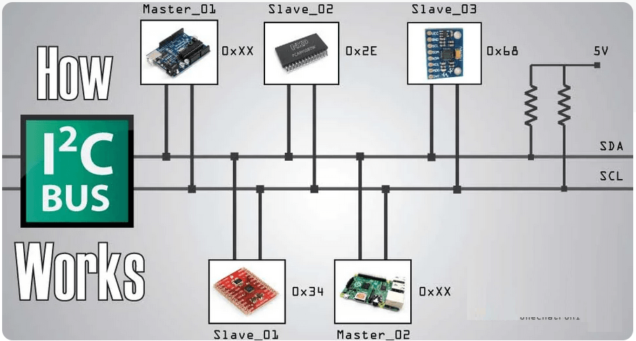
I2C is a communication protocol for serial communication between the devices or it can also be termed as a two-wire communication as it uses two line for communication that are :
How is it possible, a communication between so many devices with just 2 wires? Well each device has a preset ID or a unique device address so the master can choose with which devices will be communicating.
The two lines SDA and SCL are “open-drain” which means that pull up resistors needs to be attached to them so that the lines are high because the devices on the I2C bus are active low.
Commonly used values for the resistors are from 2K for higher speeds at about 400 kbps, to 10K for lower speed at about 100 kbps.
Every Arduino board comes with the dedicated I2C pins that are mainly labeled as SDA and SCL but if they are not labeled then by default the pin A4 and A5 can be used as SDA and SCL.
The great aspect about it is the possibility to combine two or more Arduino boards to operate different devices by creating one Arduino board as master and others as slave.
By doing such practice you can connect a comparatively large number of devices with Arduino and can control them quite easily.
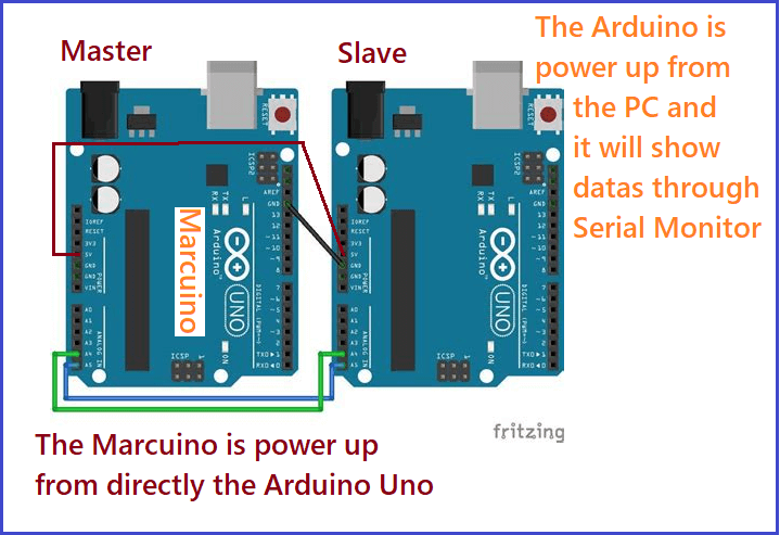
Communication between Marcuino and Arduino
My Marcuino is essencially an Arduino with an Atmega8 so in order to have an I2C connection I just need to wire pin A4 and A5 of both boards and the power line as shown below:
I2C bus schematic
In this case Marcuino is gonna act as a Master and will be power up from the Arduino Uno Slave board, that is also connected through Serial to the Computer to show datas.
real schematic
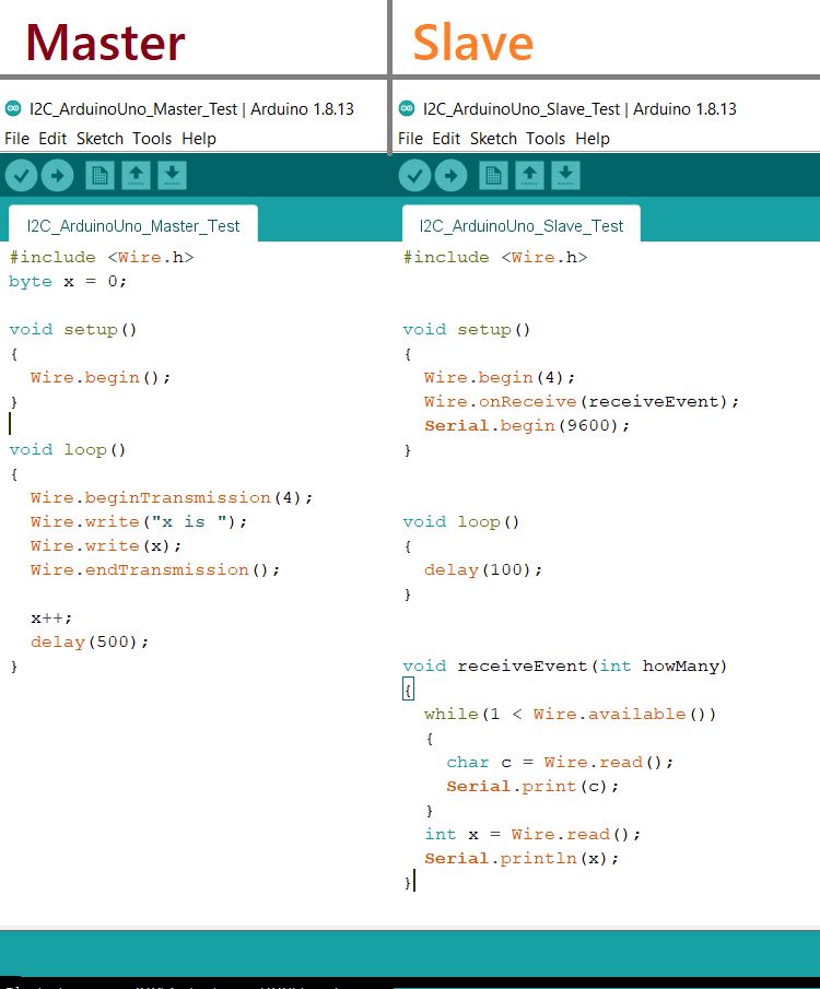
The Code
Master and Slave Code
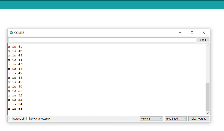
The code is very basic. The Master will send the string "x is " and byte every half a second, where the byte is a number that increase every loop cicle.
On the other hand, the Slave will receive those data. It is important to point out the Wire.onReceive(receiveEvent); function.
Basically it registers an event that will activate every time that new data is received via I2C. In our case the event is the receiveEvent
function that we define later in the code. Shortly this instruction calls the function receiveEvent each time you receive some information from I2C.
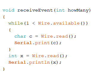
receiveEvent Function
Let's focus on the function: The condition in the while cicle is a smart way to go through all of the bytes received except the last one. That's because,
as the Master code shows, just the last byte of the data is a number, the first part is a string "x is " so these bytes go inside
a character variable one by one, and will be shown them individually on the Serial Monitor.
And the last one is then saved in an integer variable to complete the data shown as Output on the Serial Monitor.