Useful Links
comments
- Arduino CNC Shield Instructions ✔
- Calibrating the DRV8825 (Italian) ✔
- GRBL Configuration guide ✔
- Another GRBL Arduino Uno Tutorial ✔
- GRBL for SERVO ✔
Drawing Machine Projects
How to build a machine considering both Mechanical and Electronic design, this is the assignment of the week. The only one not made individually.
Beside me, my group is composed by Edu, Dhanu and Angel. We decided to realize a TicTacToe Drawing machine which
you can play with!
My part of the project involved the electronics aspect of the device, meaning:
GRBL (pronounced “gerbil”) is free and open-source firmware that controls the movement of CNC machines and can run on any boards that have an ATmega328-based microcontroller.
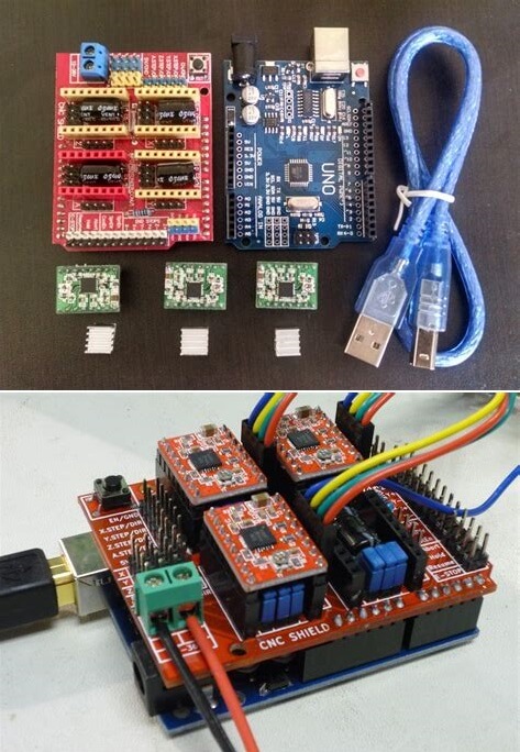
The combination of an Arduino with a CNC shield occupies very little space. The two boards are stacked on top of each other, making for a very compact setup.
Running GRBL on Arduino allows you a wide range of options: You can control stepper motors that are tiny like NEMA 11s or heavy-duty ones like NEMA 23s.
First, choosing the Stepper Motor. For our scope we took the Nema 17 (model: 42BYGH40-1.8-22A).
It comes with 2 couples of wires (one couple for each internal coil), an interesting trick to recognize which wire belong to which coil is to short a 2 random wires and see if the stator of the motor can manually move. If so then the 2 wires belong to the same coil. Like it's shown in the following video:
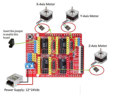
I then started preparing the CNC shield, we knew the machine had to move in the XY plane and needed a Servo, meaning 1 Stepper Motor for the Y axes and 2 Stepper Motor for the X axes (this because of the higher mass of the moveble X axes).
To achive this you need to connect the DRV8825 stepper motor drivers to the proper axes slot on the CNC shield.
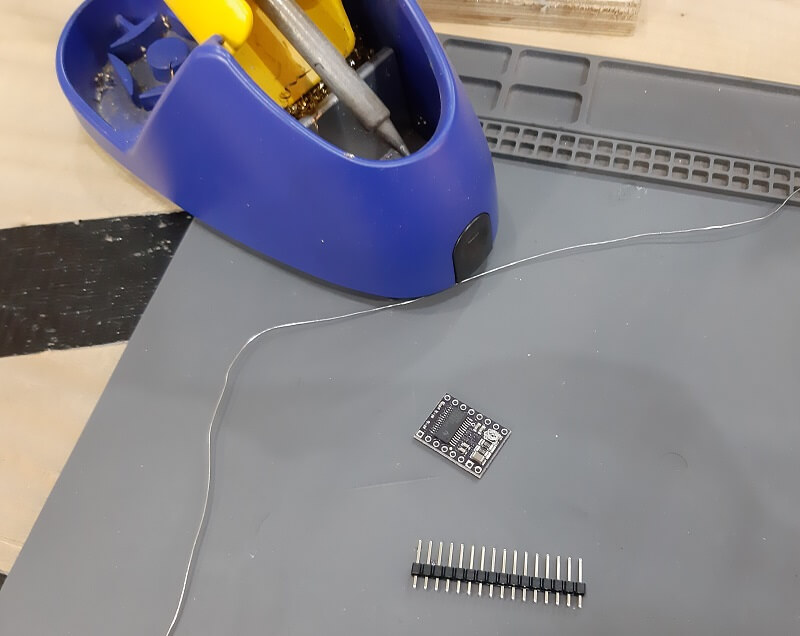
So I first started preparing the driver, soldering the pins:
Then you need to limit the current from the drivers themselfes, you cand do that adjusting the potentiometer while measuring the Voltage between the Potentiometer pin and the GND.
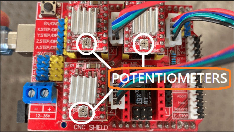
In order to do that more comfortably, I attached a Voltmeter probe to a screwdriver and the other Probe to the GND pin of the Driver.
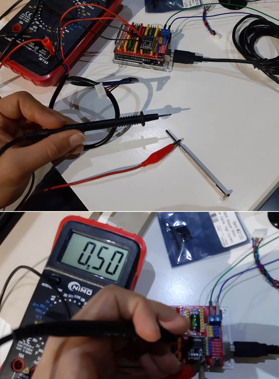
I then setted the potentiomenter considering the Voltage value needs to respect the following formula:
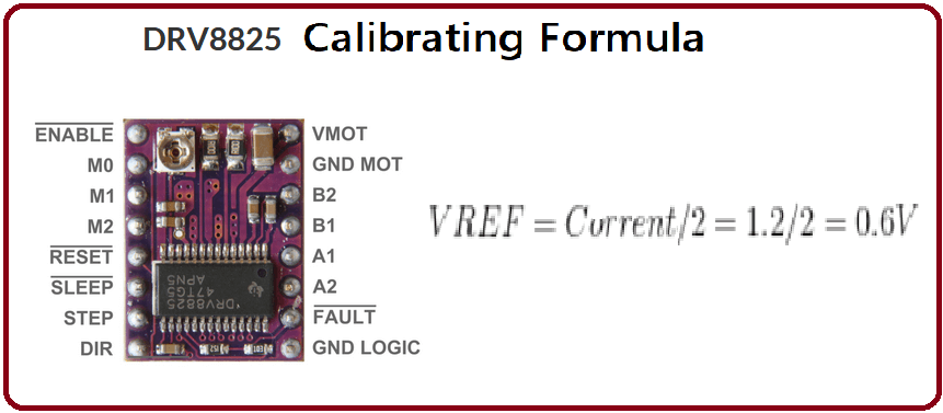
I started assuming a max current of 1.2A so with a Reference Voltage of 0.6V but then I decreased to 0.5V for optimal working configuration because either the Driver became too hot or the Stepper Motor didn't move properly.
Warning: Most of the problem on the Stepper motor movement regarded a not optimal driver calibration. So remember:
f the motor or the driver over heats, reduce the Vref. If the motor does not move or miss steps, increase the Vref.
Considering on the X axes are connected 2 Motor on the same driver you need to double the current needed, hence double the voltage reference, in our case Vref = 1.0V.
In our machine we used a Servo to control the position of the pen and a classic GRBL library wouldn't work with that. So we used a modified version of GRBL.
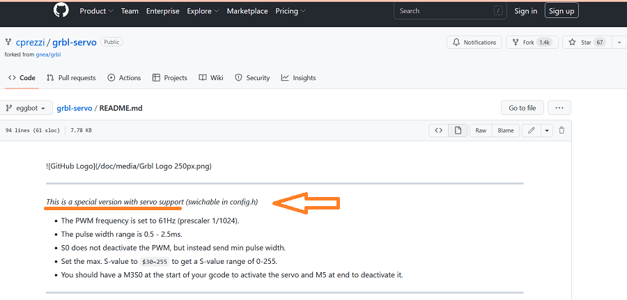
To start using the grbl into Arduino, you need to install the library into the IDE. After that you will find the specific code into the example folder to upload into the Arduino Uno.

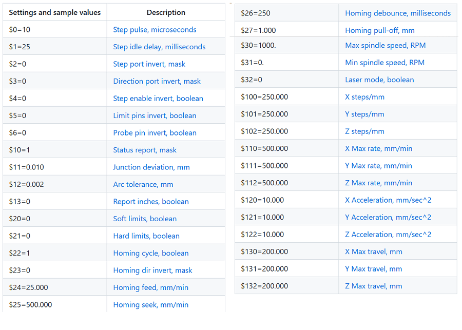
Now you can open the serial Monitor to access the help and setting configurations (you can do that by digit $ and $$ respectively). Remember to set the BaudRate at 115200. These set of configuration options will be displayed (with out comments):
And of course, the most important thing is the possibility to send G-code through it. In the following video I show one of the test moving the Y axes Motor back and forward.
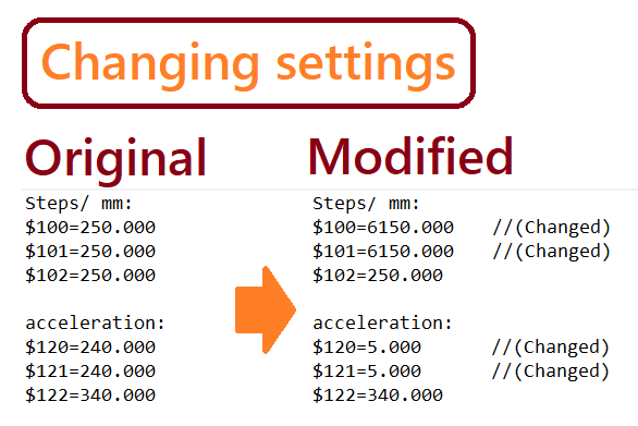
I want to point out, as shown in the video, the number of step to go from the beginning to the end of the rail is 10, I changed that under Edu's request because he calibrated his code dividing the working plane of the machine as a 10x10 step-plane and before the steps to do the same path were over 100.
In order to modify the steps I changed some of the configuration in the $$ menù:
Finally to control the Servo Motor, as the guide explained, you need to put the G-code command M6 at the beginning and then you can control it using the G-code S0 - S1000. With all that in place we finally had the full control of every motor, as is shown in the video below:
And that was my part regarding the hardware of the machine.
I then was also in charge to create the presentation video of the project.
As a Video Editing program I always use LightWorks, It is mostly unknown and maybe there are way better outthere
but it's the one I am familiar with.
The program is quite intuitive anyway, you decide the number of Video and Audio track you need and then you cut and join the part of the video as you please.
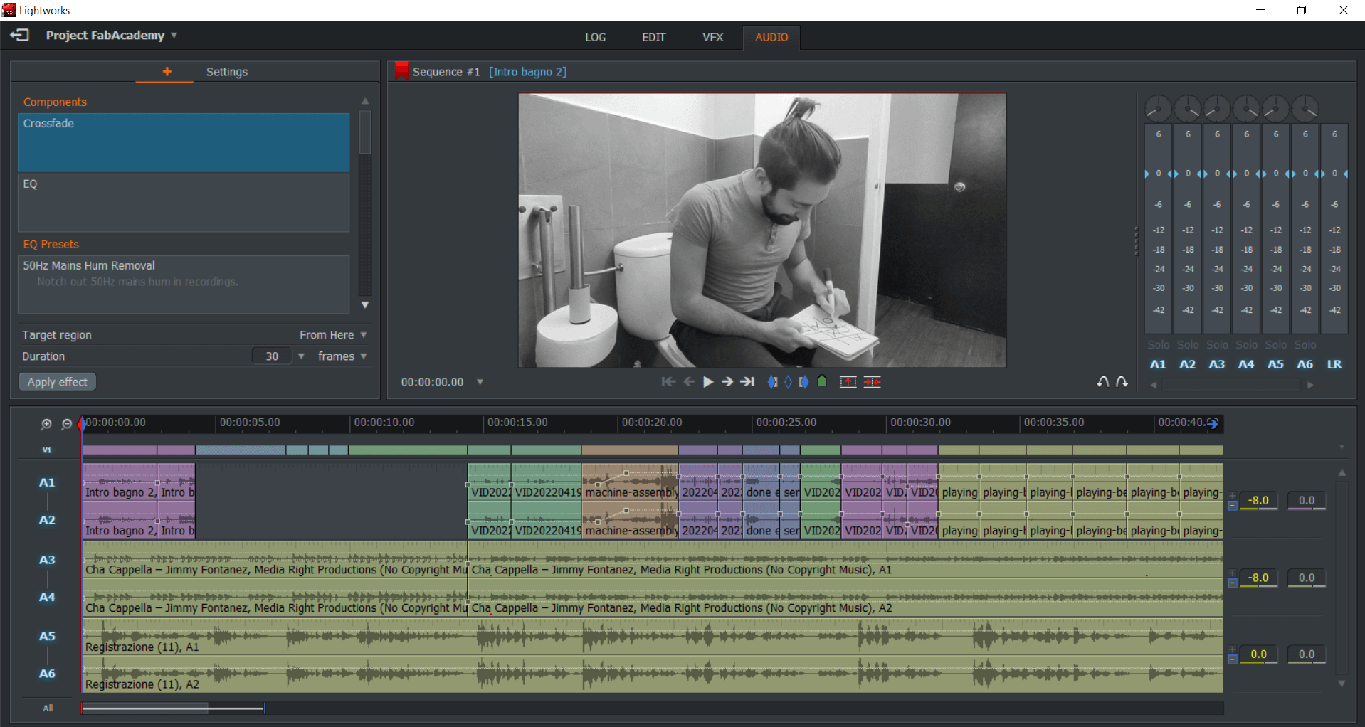
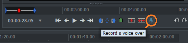
After I edited the video I just dubbed it with my voice using the rec function of the program.
I want to point out that I finished my video editing at 23:00 of my Birthday... yes my birthday, not the best way to celebrate it.
But after that I wanted to party anyway so I went to la Cueva de lobos and had an acousting jam session, it was really an amazing and emotional night. Here a sample of that night, of me singing:
Copyright © 2018 - All Rights Reserved - Domain Name
Template by OS Templates